RU2175373C1 - Door lock - Google Patents
Door lock Download PDFInfo
- Publication number
- RU2175373C1 RU2175373C1 RU2000123584A RU2000123584A RU2175373C1 RU 2175373 C1 RU2175373 C1 RU 2175373C1 RU 2000123584 A RU2000123584 A RU 2000123584A RU 2000123584 A RU2000123584 A RU 2000123584A RU 2175373 C1 RU2175373 C1 RU 2175373C1
- Authority
- RU
- Russia
- Prior art keywords
- flange
- protrusions
- fungus
- spring
- combination mechanism
- Prior art date
Links
- 239000000463 material Substances 0.000 claims abstract description 4
- 239000007779 soft material Substances 0.000 claims abstract description 3
- 241000233866 Fungi Species 0.000 claims description 17
- 230000013011 mating Effects 0.000 claims description 2
- 230000000903 blocking effect Effects 0.000 abstract description 6
- 241000826860 Trapezium Species 0.000 abstract 1
- 230000000694 effects Effects 0.000 abstract 1
- 239000000126 substance Substances 0.000 abstract 1
- 239000011159 matrix material Substances 0.000 description 7
- 239000010410 layer Substances 0.000 description 5
- 230000006835 compression Effects 0.000 description 2
- 238000007906 compression Methods 0.000 description 2
- 238000005516 engineering process Methods 0.000 description 2
- 238000000034 method Methods 0.000 description 2
- 238000003825 pressing Methods 0.000 description 2
- 230000028327 secretion Effects 0.000 description 2
- 230000005484 gravity Effects 0.000 description 1
- 239000000696 magnetic material Substances 0.000 description 1
- 238000004519 manufacturing process Methods 0.000 description 1
- 230000001681 protective effect Effects 0.000 description 1
- 230000000284 resting effect Effects 0.000 description 1
- 239000002356 single layer Substances 0.000 description 1
Images
Landscapes
- Lock And Its Accessories (AREA)
Abstract
Description
Изобретение относится к запорной технике и предназначается для использования в жилых и общественных зданиях, транспортных средствах. The invention relates to locking technology and is intended for use in residential and public buildings, vehicles.
Известен кодовый магнитомеханический замок (RU 2101449, С 1,15.11.95), в котором механизм секрета содержит корпус, размещенную в нем соосно поворотную обойму с глухими отверстиями, подпружиненную матрицу, установленную в обойму с возможностью ее продольного перемещения, запирающие стержни, торцевой ключ с гнездами, в которых установлены ориентирующие магниты для управления местоположением пассивных кодирующих элементов, имеющий кинематическую связь с торцевой поверхностью обоймы. Он снабжен взаимодействующими между собой силовыми магнитами, один из которых закреплен на матрице, а другой - на ключе, при этом в корпусе выполнены кольцевая проточка и пазы, торцевой ключ имеет выступы, соответствующие пазам корпуса, для плотного прижатия к обойме и обеспечения совместного с последней вращения в кольцевой и подпружиненный узел силового магнита, причем гнезда торцевого ключа выполнены с возможностью обеспечения перестановки в них ориентирующих магнитов, а силовые магниты матрицы и торцевого ключа выполнены неотъемлемыми от соответствующих магнитопроводов для локализации потоков индукции, все запирающие стержни прямые, подпружинены и установлены по одному с возможностью продольного перемещения во втулках, жестко связанных одними торцами с матрицей, размещенных в сквозных отверстиях, по меньшей мере одно из которых эксцентричное, вкладышей, закрепленных в глухих отверстиях обоймы и образующих другими, лежащими в одной плоскости с торцами запирающих стержней, вместе с внутренними поверхностями сквозных отверстий вкладышей и основаниями глухих отверстий обоймы цилиндрические полости, в каждой из которых помещен магниточувствительный шарик, соизмеримый с торцами запирающих стержней и свободно перемещающийся в ней. A known magnetomechanical combination lock (RU 2101449, С 1,15.11.95), in which the secret mechanism comprises a housing, a coaxially rotatable holder with blind holes placed therein, a spring-loaded matrix installed in the holder with the possibility of its longitudinal movement, locking rods, socket wrench with sockets in which orienting magnets are installed to control the location of passive coding elements, having a kinematic connection with the end surface of the holder. It is equipped with interacting power magnets, one of which is mounted on the matrix, and the other on the key, while an annular groove and grooves are made in the housing, the socket wrench has protrusions corresponding to the grooves of the housing, for tight pressing against the clip and ensuring joint with the latter rotation in the annular and spring-loaded node of the power magnet, moreover, the socket of the socket key is made with the possibility of ensuring the permutation of the orienting magnets in them, and the power magnets of the matrix and the socket key are integral all the locking rods are straight, spring-loaded and installed one by one with the possibility of longitudinal movement in bushings rigidly connected by one ends with a matrix placed in through holes, at least one of which is eccentric, liners fixed in blind holes of the cage and forming others lying on the same plane with the ends of the locking rods, together with the inner surfaces of the through holes of the liners and the bases of the blind holes The cage has cylindrical cavities in each of which a magnetically sensitive ball is placed, commensurate with the ends of the locking rods and freely moving in it.
Недостатками замка являются сложность конструкции и, как следствие, нетехнологичность и высокая стоимость изготовления. The disadvantages of the castle are the complexity of the design and, as a consequence, low technology and high manufacturing costs.
Наиболее близким по технической сущности к заявляемому техническому решению (прототипом) является замок /RU 2117128, C1 E 05 В 27/10, 47/00/, который содержит механизм секрета с корпусом с кольцевой проточкой и пазом для установки ключа, размещенную в нем поворотную обойму с глухими отверстиями, матрицу с вкладышами, установленную в обойму, торцевой ключ с ориентирующими магнитами, имеющий кинематическую связь с торцевой поверхностью обоймы. Обойма механизма секрета подпружинена и имеет возможность продольного перемещения. Магниточувствительные блокирующие элементы механизма секрета выполнены в виде шариков и установлены в цилиндрических полостях, образованных основаниями глухих отверстий обоймы и торцами с углублениями вкладышей матрицы, по меньшей мере одно из которых эксцентричное. Обойма торцевого ключа с ориентирующими магнитами подпружинена и имеет возможность автономного поворота. The closest in technical essence to the claimed technical solution (prototype) is a lock / RU 2117128, C1 E 05
Основными недостатками прототипа являются сложность конструкции матрицы механизма секрета с установленными в ней вкладышами и торцевого ключа. Необходимость совмещения штифта торцевого ключа с соответствующим пазом на корпусе механизма секрета в процессе отпирания/запирания замка в значительной степени затрудняет этот процесс, особенно в условиях пониженной освещенности. С течением времени штифт торцевого ключа истирается, что приводит к снижению надежности работы замка. The main disadvantages of the prototype are the complexity of the design of the matrix of the secret mechanism with the liners installed in it and the socket wrench. The necessity of combining the socket wrench pin with the corresponding groove on the body of the secret mechanism in the process of unlocking / locking the lock greatly complicates this process, especially in low light conditions. Over time, the socket wrench pin is worn out, which leads to a decrease in the reliability of the lock.
Технический результат, достигаемый в предлагаемом изобретении, заключается в устранении недостатков прототипа и повышении надежности в эксплуатации. The technical result achieved in the present invention is to eliminate the disadvantages of the prototype and increase the reliability in operation.
Это обеспечивается тем, что предлагаемый авторами дверной замок содержит механизм секрета, имеющий корпус, вкладыши, блокирующие элементы, выполненные в виде шариков из магнитомягкого материала, торцевой ключ с ориентирующими магнитами, сопрягаемый с торцевой поверхностью механизма секрета, и запорный орган, отличающийся тем, что в корпусе механизма секрета установлен подпружиненный грибок с возможностью его продольного перемещения, состоящий из стержня с сечением в виде правильного шестиугольника, имеющего проточку и паз, проходящего через шестиугольное отверстие запорной втулки, зафиксированной в корпусе, и фланца, выполненного из магнитопроницаемого материала, на наружной стороне которого выполнены выступы. Корпус механизма секрета имеет наружный фланец в виде несимметричной в свету относительно одной оси геометрической фигуры, например трапеции, и внутренний фланец, в который упираются выступы грибка. Грани выступов фланца грибка, обращенные к его оси, повторяют конфигурацию внутреннего фланца корпуса. Стержень грибка и плотно размещенные вокруг него вкладыши с поперечным сечением в виде правильных шестиугольников стянуты по периферии пружиной. При этом ни один из вкладышей не может самопроизвольно изменить своего положения относительно остальных, а в случае вращения стержня вокруг оси вкладыши будут вращаться вместе с ним. Количество слоев или колец из вкладышей определяется габаритами механизма секрета замка и требуемым количеством кодов. Подошва торцевого ключа выполнена в виде фигуры, повторяющей в плане форму выреза внутреннего фланца корпуса механизма секрета. This is ensured by the fact that the door lock proposed by the authors contains a secret mechanism having a body, inserts, blocking elements made in the form of balls of magnetically soft material, a socket key with orienting magnets, mating with the end surface of the secret mechanism, and a locking member, characterized in that a spring-loaded fungus is installed in the body of the secret mechanism with the possibility of its longitudinal movement, consisting of a rod with a cross section in the form of a regular hexagon having a groove and a groove passing about through the hexagonal hole of the locking sleeve fixed in the housing, and a flange made of magnetically permeable material, on the outside of which protrusions are made. The body of the secretion mechanism has an outer flange in the form of an asymmetrical light relative to one axis of a geometric figure, for example a trapezoid, and an inner flange in which the protrusions of the fungus abut. The faces of the protrusions of the fungus flange facing its axis repeat the configuration of the inner flange of the casing. The fungus rod and the liners tightly placed around it with a cross section in the form of regular hexagons are pulled together around the periphery by a spring. In this case, none of the liners can spontaneously change its position relative to the rest, and in the case of rotation of the rod around the axis of the liners will rotate with it. The number of layers or rings from the inserts is determined by the dimensions of the lock secret mechanism and the required number of codes. The sole of the socket wrench is made in the form of a figure repeating in plan a cut-out shape of the inner flange of the body of the secret mechanism.
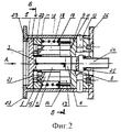
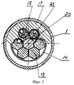
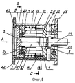
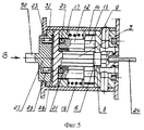
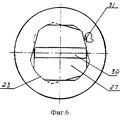
На фиг. 1 приведено расположение вкладышей вокруг стержня грибка в три слоя, где а - стержень, b - шестигранный вкладыш первого слоя, с - вкладыш второго слоя, d - вкладыш третьего слоя, e - стяжная пружина; на фиг. 2 - сечение по оси механизма секрета замка с однослойным расположением вкладышей в закрытом положении; на фиг. 3 - сечение по Б-Б; на фиг. 4 - вид по стрелке А; на фиг. 5 - механизм секрета с приставленным к нему торцевым ключом в открытом положении; на фиг. 6 - вид по стрелке В. In FIG. 1 shows the location of the liners around the fungus rod in three layers, where a is the rod, b is the hexagonal liner of the first layer, c is the liner of the second layer, d is the liner of the third layer, e is the compression spring; in FIG. 2 is a section along the axis of the lock secret mechanism with a single-layer arrangement of liners in the closed position; in FIG. 3 - section BB; in FIG. 4 is a view along arrow A; in FIG. 5 - secret mechanism with a socket wrench attached to it in the open position; in FIG. 6 is a view along arrow B.
Конструкция дверного замка включает в себя корпус 1 механизма секрета, в котором установлен грибок 2, состоящий из имеющего в сечении вид правильного шестиугольника стержня 3 и фланца 4, выполненного из магнитопроницаемого материала. На наружной стороне фланца 4 выполнены выступы 5, а на стержне - проточка 6 и паз 7. The design of the door lock includes a body 1 of the secret mechanism, in which a fungus 2 is installed, consisting of a sectional view of a regular hexagon of the
Стержень 3 проходит через шестиугольное отверстие 8 запорной втулки 9, зафиксированной в корпусе 1 механизма секрета штифтами 10. The
На торец 11 запорной втулки 9 опираются вкладыши 12, размещенные вокруг стержня 3. Вкладыши 12, имеющие в сечении 13 форму правильного шестиугольника, равного сечению стержня 3, плотно прижаты к стержню 3 стяжной пружиной 14. On the end 11 of the
Цилиндрическими концами 15 вкладыши 12 входят в отверстия 16 сепаратора 17. Сепаратор 17 поджимается к внутренней стороне фланца 4 грибка 2 пружиной 18, опирающейся на шайбу 19, которая, в свою очередь, упирается в шестигранники 13 вкладышей 12. The
Между внутренней поверхностью фланца 4 и торцами вкладышей 12 в отверстиях 16 сепаратора 17 находятся блокирующие шарики 20, выполненные из магнитомягкого материала, а в торцах цилиндрических концов 15 вкладышей 12 выполнены пазы 21 под шарики 20. Пазы 21 - по одному на вкладыш - располагаются на периферии или по центру торцов вкладышей 12. Between the inner surface of the
Корпус 1 механизма секрета имеет наружный фланец 22 и внутренний фланец 23, в который упираются выступы 5 грибка 2. В свету внутренний фланец 23 имеет вид несимметричной относительно одной оси геометрической фигуры, например трапеции, для однозначной ориентации ключа, прикладываемого к наружной поверхности фланца 4. The body 1 of the secret mechanism has an
Грани выступов 5 фланца 4, обращенные к его оси, повторяют конфигурацию фланца 23. The faces of the
Открытие/закрытие замка осуществляется путем поворота в ту или иную сторону поводка 24, который входит в паз на конце стержня 3. От выпадения поводок 24 удерживается пружинным кольцом 25. Opening / closing the lock is carried out by turning in one direction or another the
Защитная планка 26 препятствует вырыванию или повороту механизма секрета вокруг его оси. The
В закрытом положении замка (фиг. 2) блокирующие шарики 20 находятся в зазоре между внутренней поверхностью фланца 4 грибка 2 и торцами 12, а шестигранная часть стержня 3 - в шестиугольном отверстии 8 опорной втулки 9, вследствие чего исключается перемещение грибка 2 вдоль оси или поворот вокруг нее. In the closed position of the lock (Fig. 2), the
Открывается замок с помощью торцевого ключа 27, подошва 28 которого имеет в плане форму, повторяющую форму выреза фланца 23. Торцевой ключ 27 с предварительно установленными в нем, в соответствии с заданным кодом, ориентирующими магнитами 29 плотно приставляется к наружной поверхности фланца 4 грибка 2 механизма секрета. Блокирующие шарики 20 под действием магнитного поля ориентирующих магнитов 29, в соответствии с заданным кодом, занимают положения напротив пазов 21. Нажатие на торцевой ключ 27 приводит к продольному перемещению грибка 2 и вхождению блокирующих шариков 20 в пазы 21 вкладышей 12. При этом в шестиугольном отверстии 8 опорной втулки 9 оказывается проточка 6 стержня 3. При повороте торцевого ключа 27 и соответственно поводка 24 за ручку 30 происходит открытие замка. В процессе вращения торцевого ключа 27 выступы 31 на его подошве заходят под внутренний фланец 23 и не дают возможность отсоединить ключ до завершения открытия замка, когда торцевой ключ возвращается в свое первоначальное положение. The lock is opened using a
По возвращении торцевого ключа 27 в первоначальное положение его подошва 28 выходит из-под фланца 23, пружина 18 через сепаратор 17 перемещает грибок 2 до его упора во фланец 23, а проточка 6 на стержне 3 выходит из шестиугольного отверстия 8. Одновременно между внутренней поверхностью фланца 4 и торцами вкладышей 12 вновь образуется зазор. Поскольку поле магнитов 29 продолжает удерживать блокирующие шарики 20 на внутренней поверхности фланца 4, последние выходят из пазов 21 вкладышей 12. При отсоединении торцевого ключа 27 блокирующие шарики 20 под действием силы тяжести опускаются, оставаясь внутри отверстий 16 сепаратора 17. Механизм секрета замка переходит в закрытое положение. Upon returning the
В случае использования торцевого ключа 27 с кодом, отличным от кода замка, по меньшей мере один блокирующий шарик 20 останется между внутренней поверхностью фланца 4 и вкладыша 12, сохраняя зазор и не позволяя тем самым открыть замок. In the case of using a
Смена кода замка и торцевого ключа осуществляется поворотом вкладышей 12 с пазами 21 механизма секрета и соответствующим изменением расположения ориентирующих магнитов 29 торцевого ключа 27. The lock code and the socket key are changed by turning the
Claims (1)
Priority Applications (1)
| Application Number | Priority Date | Filing Date | Title |
|---|---|---|---|
| RU2000123584A RU2175373C1 (en) | 2000-09-14 | 2000-09-14 | Door lock |
Applications Claiming Priority (1)
| Application Number | Priority Date | Filing Date | Title |
|---|---|---|---|
| RU2000123584A RU2175373C1 (en) | 2000-09-14 | 2000-09-14 | Door lock |
Publications (1)
| Publication Number | Publication Date |
|---|---|
| RU2175373C1 true RU2175373C1 (en) | 2001-10-27 |
Family
ID=20240022
Family Applications (1)
| Application Number | Title | Priority Date | Filing Date |
|---|---|---|---|
| RU2000123584A RU2175373C1 (en) | 2000-09-14 | 2000-09-14 | Door lock |
Country Status (1)
| Country | Link |
|---|---|
| RU (1) | RU2175373C1 (en) |
Cited By (8)
| Publication number | Priority date | Publication date | Assignee | Title |
|---|---|---|---|---|
| RU2216628C1 (en) * | 2002-08-13 | 2003-11-20 | Камынин Юрий Андреевич | Combination mechanism of high resistance to breaking-in |
| RU2239692C1 (en) * | 2003-04-16 | 2004-11-10 | Камынин Юрий Андреевич | Secrecy mechanism for lock |
| RU2253727C1 (en) * | 2004-08-10 | 2005-06-10 | Сергеев Евгений Николаевич | Magnetic lock secrecy mechanism with radial key |
| RU2253724C2 (en) * | 2003-08-01 | 2005-06-10 | Камынин Юрий Андреевич | Secrecy mechanism for high-reliability lock with increased resistance to breaking-in |
| RU2253726C1 (en) * | 2003-09-18 | 2005-06-10 | Камынин Юрий Андреевич | Secrecy mechanism with free locking members |
| RU2253725C2 (en) * | 2003-08-07 | 2005-06-10 | Камынин Юрий Андреевич | Doubled secrecy mechanism with free locking members |
| RU2318968C1 (en) * | 2006-05-02 | 2008-03-10 | Олег Владимирович Кучма | Device for access code input in executive mechanism controller of lock |
| RU2339780C1 (en) * | 2007-03-21 | 2008-11-27 | Евгений Николаевич Сергеев | Magnetically-operated secrecy mechanism |
Citations (6)
| Publication number | Priority date | Publication date | Assignee | Title |
|---|---|---|---|---|
| US3948068A (en) * | 1975-05-14 | 1976-04-06 | American Locker Company, Inc. | Magnetic lock |
| US4285220A (en) * | 1977-12-29 | 1981-08-25 | Tomomasa Kajita | Magnetically operable lock |
| US4307589A (en) * | 1978-01-13 | 1981-12-29 | Tomomasa Kajita | Magnetic lock construction |
| US4397166A (en) * | 1978-12-28 | 1983-08-09 | Evva-Werk Spezialerzeugung Von Zylinder-Und Sicherheitsschloessern Gmbh & Co. | Magnetic lock having a bolt and locking pieces |
| DE3209946A1 (en) * | 1982-03-18 | 1983-09-22 | Slavko 7452 Haigerloch Pavlovic | Rotary cylinder lock |
| RU2117128C1 (en) * | 1997-03-31 | 1998-08-10 | Товарищество с ограниченной ответственностью "Научно-производственное объединение "ЛИКЧЕЛ" | Coded magnetomechanical lock |
-
2000
- 2000-09-14 RU RU2000123584A patent/RU2175373C1/en active
Patent Citations (6)
| Publication number | Priority date | Publication date | Assignee | Title |
|---|---|---|---|---|
| US3948068A (en) * | 1975-05-14 | 1976-04-06 | American Locker Company, Inc. | Magnetic lock |
| US4285220A (en) * | 1977-12-29 | 1981-08-25 | Tomomasa Kajita | Magnetically operable lock |
| US4307589A (en) * | 1978-01-13 | 1981-12-29 | Tomomasa Kajita | Magnetic lock construction |
| US4397166A (en) * | 1978-12-28 | 1983-08-09 | Evva-Werk Spezialerzeugung Von Zylinder-Und Sicherheitsschloessern Gmbh & Co. | Magnetic lock having a bolt and locking pieces |
| DE3209946A1 (en) * | 1982-03-18 | 1983-09-22 | Slavko 7452 Haigerloch Pavlovic | Rotary cylinder lock |
| RU2117128C1 (en) * | 1997-03-31 | 1998-08-10 | Товарищество с ограниченной ответственностью "Научно-производственное объединение "ЛИКЧЕЛ" | Coded magnetomechanical lock |
Cited By (8)
| Publication number | Priority date | Publication date | Assignee | Title |
|---|---|---|---|---|
| RU2216628C1 (en) * | 2002-08-13 | 2003-11-20 | Камынин Юрий Андреевич | Combination mechanism of high resistance to breaking-in |
| RU2239692C1 (en) * | 2003-04-16 | 2004-11-10 | Камынин Юрий Андреевич | Secrecy mechanism for lock |
| RU2253724C2 (en) * | 2003-08-01 | 2005-06-10 | Камынин Юрий Андреевич | Secrecy mechanism for high-reliability lock with increased resistance to breaking-in |
| RU2253725C2 (en) * | 2003-08-07 | 2005-06-10 | Камынин Юрий Андреевич | Doubled secrecy mechanism with free locking members |
| RU2253726C1 (en) * | 2003-09-18 | 2005-06-10 | Камынин Юрий Андреевич | Secrecy mechanism with free locking members |
| RU2253727C1 (en) * | 2004-08-10 | 2005-06-10 | Сергеев Евгений Николаевич | Magnetic lock secrecy mechanism with radial key |
| RU2318968C1 (en) * | 2006-05-02 | 2008-03-10 | Олег Владимирович Кучма | Device for access code input in executive mechanism controller of lock |
| RU2339780C1 (en) * | 2007-03-21 | 2008-11-27 | Евгений Николаевич Сергеев | Magnetically-operated secrecy mechanism |
Similar Documents
| Publication | Publication Date | Title |
|---|---|---|
| US7000441B2 (en) | Lock cylinder assembly | |
| US3633393A (en) | Lock having magnets incorporated in rotary tumblers | |
| RU2175373C1 (en) | Door lock | |
| US3878700A (en) | Lock for operation by an axially bitted key | |
| JP7278265B2 (en) | locking device | |
| PL194596B1 (en) | Cylinder lock | |
| US10125521B2 (en) | Magnetic lock system | |
| CN109629915A (en) | A kind of magnetic force primary and secondary bead lock core and its solution lock key | |
| RU2117128C1 (en) | Coded magnetomechanical lock | |
| WO2000057008A1 (en) | Cylinder lock combined with a magnetic pin and a non-magnetic pin | |
| JP4360515B2 (en) | Magnet cylinder lock | |
| RU2193088C1 (en) | Mortise cylinder magnetomechanical coded lock | |
| RU2156343C1 (en) | Door lock without key hole | |
| RU2030534C1 (en) | Lock cylinder mechanism | |
| RU2207432C1 (en) | Type freeblock secret mechanism of enhanced resistance to breaking in | |
| RU97104939A (en) | MAGNETIC MECHANICAL LOCK | |
| RU2239692C1 (en) | Secrecy mechanism for lock | |
| RU2244087C1 (en) | Magnetocontrolled lock secrecy mechanism | |
| JP4350870B2 (en) | Inner cylinder rotation control mechanism of electronic cylinder lock | |
| RU2339780C1 (en) | Magnetically-operated secrecy mechanism | |
| SU1767140A1 (en) | Locking mechanism of lock | |
| RU2135718C1 (en) | Cylindrical mechanism of lock with key | |
| RU2093654C1 (en) | Interlocking unit of lock | |
| RU2216628C1 (en) | Combination mechanism of high resistance to breaking-in | |
| RU2125639C1 (en) | Ball-type cylindrical mechanism of lock secrecy with key |