RU2168453C2 - Transportation device - Google Patents
Transportation device Download PDFInfo
- Publication number
- RU2168453C2 RU2168453C2 RU99103297/12A RU99103297A RU2168453C2 RU 2168453 C2 RU2168453 C2 RU 2168453C2 RU 99103297/12 A RU99103297/12 A RU 99103297/12A RU 99103297 A RU99103297 A RU 99103297A RU 2168453 C2 RU2168453 C2 RU 2168453C2
- Authority
- RU
- Russia
- Prior art keywords
- conveyor line
- transporting
- transport device
- bodies
- transporting bodies
- Prior art date
Links
Images


Classifications
-
- B—PERFORMING OPERATIONS; TRANSPORTING
- B65—CONVEYING; PACKING; STORING; HANDLING THIN OR FILAMENTARY MATERIAL
- B65H—HANDLING THIN OR FILAMENTARY MATERIAL, e.g. SHEETS, WEBS, CABLES
- B65H29/00—Delivering or advancing articles from machines; Advancing articles to or into piles
- B65H29/58—Article switches or diverters
- B65H29/60—Article switches or diverters diverting the stream into alternative paths
-
- B—PERFORMING OPERATIONS; TRANSPORTING
- B65—CONVEYING; PACKING; STORING; HANDLING THIN OR FILAMENTARY MATERIAL
- B65H—HANDLING THIN OR FILAMENTARY MATERIAL, e.g. SHEETS, WEBS, CABLES
- B65H29/00—Delivering or advancing articles from machines; Advancing articles to or into piles
- B65H29/003—Delivering or advancing articles from machines; Advancing articles to or into piles by grippers
-
- B—PERFORMING OPERATIONS; TRANSPORTING
- B65—CONVEYING; PACKING; STORING; HANDLING THIN OR FILAMENTARY MATERIAL
- B65H—HANDLING THIN OR FILAMENTARY MATERIAL, e.g. SHEETS, WEBS, CABLES
- B65H2301/00—Handling processes for sheets or webs
- B65H2301/30—Orientation, displacement, position of the handled material
- B65H2301/32—Orientation of handled material
- B65H2301/323—Hanging
-
- B—PERFORMING OPERATIONS; TRANSPORTING
- B65—CONVEYING; PACKING; STORING; HANDLING THIN OR FILAMENTARY MATERIAL
- B65H—HANDLING THIN OR FILAMENTARY MATERIAL, e.g. SHEETS, WEBS, CABLES
- B65H2405/00—Parts for holding the handled material
- B65H2405/50—Gripping means
- B65H2405/55—Rail guided gripping means running in closed loop, e.g. without permanent interconnecting means
Abstract
Description
Изобретение относится к транспортному устройству согласно ограничительной части пункта 1 формулы изобретения. The invention relates to a transport device according to the restrictive part of
Транспортное устройство этого рода известно из заявки CH-A-382768 (или соответствующего патента US-A-3032341), согласно которой транспортирующие органы принудительно перемещаются вдоль замкнутой конвейерной линии транспортным средством, а вдоль участков с уклоном вниз - под действием силы тяжести. Вдоль этой замкнутой конвейерной линии расположена загрузочная позиция для ввода в транспортирующие органы транспортируемых печатных изделий, а также разгрузочная позиция, в которой печатные изделия снимаются с транспортирующих органов. Разгруженные транспортирующие органы возвращаются в загрузочную позицию. В упомянутой выше публикации описан также вариант исполнения, при котором конвейерная линия в зоне загрузочной позиции разделяется на две ветви, каждая из которых ведет к своей разгрузочной позиции. Транспортирующие органы подводятся поочередно к одной из двух ветвей. Поэтому в разгрузочные позиции каждый раз поступает половина печатных изделий, принятых транспортирующими органами в загрузочной позиции. Следовательно, каждая разгрузочная позиция и относящаяся к ней обрабатывающая станция могут работать с соответственно меньшей скоростью. A transport device of this kind is known from the application CH-A-382768 (or the corresponding patent US-A-3032341), according to which transporting bodies are forcibly moved along a closed conveyor line by a vehicle, and along sections with a downward slope under gravity. Along this closed conveyor line there is a loading position for entering transported printed products into the transporting bodies, as well as an unloading position in which the printed products are removed from the transporting bodies. The unloaded transporting bodies return to the loading position. The publication mentioned above also describes an embodiment in which the conveyor line in the area of the loading position is divided into two branches, each of which leads to its unloading position. The transporting bodies are led alternately to one of the two branches. Therefore, each time half of the printed products received by the transporting bodies in the loading position enter the unloading position. Therefore, each unloading position and its associated processing station can operate at a correspondingly lower speed.
Задача данного изобретения заключается в том, чтобы создать транспортное устройство вышеуказанного рода, которое открывает более широкие возможности применения, чем описанное выше транспортное устройство согласно уровню техники. The objective of the invention is to create a transport device of the above kind, which opens up wider application possibilities than the transport device described above according to the prior art.
Согласно изобретению эта задача решается транспортным устройством, обладающим признаками пунктов 1-15 формулы изобретения. According to the invention, this problem is solved by a transport device having the features of paragraphs 1-15 of the claims.
В пункте ответвления или ввода как порожние транспортирующие органы, так и транспортирующие органы, загруженные транспортируемыми предметами, можно по отдельности или группами извлекать из конвейерной линии или вводить в нее. Благодаря этому можно простыми средствами повлиять нужным образом на число и последовательность транспортирующих органов, перемещаемых вдоль данной конвейерной линии. Это имеет значение прежде всего тогда, когда между транспортирующими органами, на которых находятся транспортируемые предметы, есть порожние транспортирующие органы, которые нежелательны, или когда транспортирующие органы несут одинаковые или разнородные предметы, которые не все имеют одинаковое место назначения. At the branch or entry point, both empty transporting bodies and transporting bodies loaded with transported items can be individually or in groups removed from the conveyor line or introduced into it. Due to this, it is possible by simple means to influence the number and sequence of transporting organs moving along a given conveyor line as needed. This is especially important when there are empty transporting bodies that are undesirable between the transporting bodies on which the transported objects are located, or when the transporting bodies carry identical or dissimilar objects that do not all have the same destination.
Предпочтительные варианты исполнения транспортного устройства согласно изобретению служат предметом зависимых пунктов формулы изобретения. Preferred embodiments of the transport device according to the invention are the subject of the dependent claims.
Ниже при помощи чертежей подробнее описываются примеры исполнения предмета изобретения. Чисто схематически показаны:
на фиг. 1 и 2 - часть конвейерной ленты с пунктом ответвления и с установленным здесь стрелочным переводом в двух разных положениях,
на фиг. 3 и 4 - часть конвейерной линии с пунктом ввода и с установленным здесь стрелочным переводом в двух разных положениях,
на фиг. 5-7 - часть другого варианта исполнения конвейерной линии с пунктом ответвления для извлечения порожних транспортирующих органов в различных эксплуатационных состояниях,
на фиг. 8 - часть другой формы исполнения конвейерной линии с позицией ввода,
на фиг. 9 - транспортное устройство с основной конвейерной линией, выполненной в виде замкнутой петли с пунктами ответвления и ввода, а также с загрузочной и разгрузочной позициями,
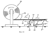
на фиг. 10 и 11 - другие варианты исполнения загрузочной позиции транспортирующего устройства того рода, который показан на фиг. 9,
на фиг. 12 - часть другого варианта исполнения транспортного устройства с загрузочной и разгрузочной позициями,
на фиг. 13 и 14 - часть транспортного устройства согласно изобретению с другим вариантом исполнения загрузочной позиции.Below, using the drawings, examples of the execution of the subject of the invention are described in more detail. Purely schematically shown:
in FIG. 1 and 2 - part of the conveyor belt with a branch point and with the turnout installed here in two different positions,
in FIG. 3 and 4 - part of the conveyor line with the entry point and with the switch installed here in two different positions,
in FIG. 5-7 are part of another embodiment of a conveyor line with a branch point for removing empty transporting bodies in various operating conditions,
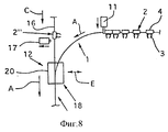
in FIG. 8 is a part of another embodiment of a conveyor line with an input position,
in FIG. 9 - transport device with a main conveyor line, made in the form of a closed loop with points of branching and input, as well as loading and unloading positions,
in FIG. 10 and 11 are other embodiments of the loading position of the conveying device of the kind shown in FIG. 9,
in FIG. 12 is a part of another embodiment of a transport device with loading and unloading positions,
in FIG. 13 and 14 are part of a transport device according to the invention with another embodiment of the loading position.
На фиг. 1 и 2 показана часть первой конвейерной линии 1 (называемой в дальнейшем также основной конвейерной линией), вдоль которой перемещаются в направлении A изображенные лишь схематически транспортирующие органы 2. Транспортирующие органы 2 отделены друг от друга, т.е. не сцеплены между собой и поэтому не зависят друг от друга. Во всех показанных на схемах примерах исполнения транспортирующие органы имеют управляемые захваты 3, которые закреплены в салазках или каретках 4. Захваты 3 держат предметы 5, которыми в изображенных примерах исполнения являются печатные изделия, в частности газеты, журналы, брошюры и т.п., а также вкладки к таким печатным изделиям. В примере исполнения согласно фиг. 1 и 2 эти предметы 5 транспортируются в висячем положении. In FIG. 1 and 2, a part of the first conveyor line 1 (hereinafter also referred to as the main conveyor line) is shown along which only the schematically transporting
На основной конвейерной линии 1 находится пункт 6 ответвления со стрелочным переводом 7. В последнем имеется поворотная стрелка 8, которую можно при помощи исполнительного органа 9 перевести в одно из двух положений. Из пункта 6 ответвления выходит вторая конвейерная линия 10, которая в дальнейшем будет именоваться ответвленной конвейерной линией. В направлении транспортировки A перед пунктом 6 ответвления установлен задерживающий орган 11, который можно вводить в линию движения транспортирующего органа 2, приближающегося в направлении A к пункту 6 ответвления, чтобы задержать его. On the
На фиг. 1 стрелка 8 занимает положение, в котором она находится в основной конвейерной линии 1. Поэтому транспортирующие органы 2 перемещаются вдоль этой основной конвейерной линии. Для того чтобы перевести транспортирующие органы 2 в ответвленную конвейерную линию 10, вводится в действие задерживающий орган 11, останавливающий поступающие транспортирующие органы 2. Когда стрелка 8 освободится от транспортирующих органов 2, ее переводят при помощи исполнительного органа 9 в показанное на фиг. 2 второе положение. Затем задерживающий орган 11 выключают, открывая свободный путь транспортирующим органам 2. Теперь обозначенные 2' транспортирующие органы перемещаются в направлении В вдоль ответвленной конвейерной линии 10. In FIG. 1,
Когда нужное число транспортирующих органов 2 будет пропущено через ответвленную конвейерную линию 10, вступает в действие задерживающий орган 11, в результате чего снова задерживаются поступающие транспортирующие органы 2 (фиг. 2). Когда освобождается стрелка 8, ее переводят обратно. После выключения задерживающего органа 11 транспортирующие органы 2 получают возможность дальнейшего перемещения вдоль основной конвейерной линии 1 (см. фиг. 1). When the required number of
Способ перемещения транспортирующих органов 2 вдоль конвейерных линий 1 и 10 на фиг. 1 и 2 подробнее не иллюстрируется. Для этого могут быть применены известные подающие устройства или, как это показано на примере наклонной ответвленной конвейерной линии 10, можно использовать силу тяжести. The method for moving the
На фиг. 3 и 4 в изображении, соответствующем фиг. 1 и 2, показан вариант исполнения, при котором в первой основной конвейерной линии 1 находится пункт ввода 12. В этом пункте ввода 12 тоже предусмотрен стрелочный перевод 13 с поворотной стрелкой 14. Для переключения стрелки 14 служит исполнительный орган 15. В пункт ввода 12 ведет вторая конвейерная линия 16 (подающая), оснащенная управляемым задерживающим органом 17, который расположен перед пунктом ввода 12 в направлении C транспортировки вдоль второй конвейерной линии 16. In FIG. 3 and 4 in the image corresponding to FIG. 1 and 2, an embodiment is shown in which an
В изображении согласно фиг. 3 стрелка 14 находится в основной конвейерной линии 1. Поэтому транспортирующие органы 2 перемещаются в направлении А вдоль основной конвейерной линии 1. Для того чтобы ввести транспортирующие органы 2 в первую конвейерную линию 1, переключают задерживающий орган 11, который вводится в линию движения транспортирующих органов 2, подаваемых вдоль первого участка 1 конвейера, и препятствует дальнейшему перемещению этих органов. Когда на стрелке 14 больше нет никаких транспортирующих органов 2, ее переводят при помощи исполнительного органа 15 в другое положение (фиг. 4). Подведенные по подающей линии 16 транспортирующие органы 2'' попадают теперь по стрелке 14 в основную конвейерную линию 1, перемещаясь вдоль нее в направлении A, как видно из фиг. 4. Воздействуя на задерживающий орган 16, его вводят в линию движения транспортирующих органов 2'', поступающих вдоль подающей линии 16. В результате транспортирующие органы 2'' останавливаются. Стрелку 14 можно затем переключить обратно. Путем отвода задерживающего органа 11 из линии движения транспортирующих органов 2 их освобождают для дальнейшего перемещения вдоль основной конвейерной линии 1 (фиг. 3). In the image of FIG. 3, the
Предметы 5, подводимые в пункт ввода 12 транспортирующими органами 2'' вдоль подающей линии 16, могут быть такими же, как предметы 5, попадающие в пункт ввода 12 по основной конвейерной линии 1, или же быть иными. В последнем случае в варианте исполнения, изображенном на фиг. 3 и 4, можно перемешивать предметы 5 различного рода в любых варьируемых соотношениях.
На фиг. 5-7 показан вариант исполнения согласно фиг. 1 и 2, отличающийся прежде всего другим исполнением стрелочного перевода 7. Кроме того, в варианте исполнения согласно фиг. 5-7 предметы 5 транспортируются не в висячем, а в лежачем положении с каскадной укладкой. In FIG. 5-7 show an embodiment according to FIG. 1 and 2, characterized primarily by a different execution of the
Как показано на фиг. 6 и 7, стрелочный перевод 7 имеет в направлении D поступательно перемещаемую стрелку 18. Она имеет два участка пропуска 18а и 18б, из которых участок 18а относится к основной конвейерной линии 1 и поэтому является прямолинейным. Второй участок пропуска 18б изогнут в соответствии с кривизной второй конвейерной линии 10. Следует заметить, что при соответствующем размещении обоих участков пропуска 18а и 18б стрелочный перевод можно выполнить передвижным также и в направлении, перпендикулярном к плоскости чертежа. As shown in FIG. 6 and 7, the
Принцип действия варианта исполнения согласно фиг. 5-7 является по существу таким же, как тот, который был объяснен при помощи фиг. 1 и 2. В показанном на фиг. 7 конечном положении стрелки 18 ее участок пропуска 18а располагается вдоль первой (основной) конвейерной линии 1. Во втором конечном положении, показанном на фиг. 6, второй участок пропуска 18б стрелки 18 соединяет основную конвейерную линию 1 с ответвительной конвейерной линией 10. The principle of operation of the embodiment according to FIG. 5-7 is essentially the same as that explained with reference to FIG. 1 and 2. In the embodiment shown in FIG. 7, in the final position of the
На фиг. 5-7 показано также, как из потока транспортирующих органов 2, нагруженных предметами 5, можно извлечь отдельные порожние транспортирующие органы 2'. Для этой цели рядом с удерживающим органом 11 предусмотрен второй удерживающий орган 19, который в направлении A тоже расположен перед пунктом ответвления 6, но позади первого задерживающего органа 11. Когда непоказанное детекторное устройство установит, что к пункту ответвления 6 подходит порожний транспортирующий орган 2', в надлежащий момент времени второй задерживающий орган 19 вводится в линию движения транспортирующих органов 2, препятствуя дальнейшему движению транспортирующего органа 2' (фиг. 5). Позади этого порожнего транспортирующего органа 2' вводится первый задерживающий орган 11, останавливая следующие транспортирующие органы 2, на которых находятся предметы 5. Когда стрелка 18 освобождается, ее переключают обратно. Затем отводится второй задерживающий орган 19, и порожний транспортирующий орган 2' получает возможность дальнейшего движения. После этого порожний транспортирующий орган 2' выводится по ответвительной конвейерной линии 10, как показано на фиг. 6. Стрелку 18 переводят обратно, после чего первый задерживающий орган 11 выключают, открывая свободный путь для перемещения транспортирующих органов 2 с находящимися на них предметами 5 (фиг. 7). In FIG. 5-7 also show how separate empty transporting
На фиг. 8 в изображении, соответствующем фиг. 3 и 4, показано, как порожние транспортирующие органы 2'', подводимые вдоль конвейерной линии 16, можно ввести между порожними транспортирующими органами 2, которые перемещаются вдоль основной конвейерной линии 1 в пункт ввода 12. Здесь принцип действия такой же, какой был описан при помощи фиг. 3 и 4. Однако на фиг. 8 показана стрелка 20, выполненная аналогично стрелке 18 в примере исполнения согласно фиг. 5-7 и поступательно перемещаемая в направлении E из одного положения в другое. In FIG. 8 in the image corresponding to FIG. 3 and 4, it is shown how the empty transporting
На фиг. 9 показано транспортное устройство, в котором первая или основная конвейерная линия 1 выполнена в виде замкнутой петли и имеет ответвительные пункты 6, 6а, а также пункты ввода 12, 12а, которые были уже описаны при помощи фиг. 1-8. Это транспортное устройство имеет также загрузочную позицию 21 и разгрузочные позиции 22 и 22а, которые установлены в основной конвейерной линии 1. К разгрузочным позициям 22, 22а примыкают обрабатывающие станции 23 и 24 соответственно. In FIG. 9 shows a transport device in which the first or
В состав обрабатывающей станции 23 входит изображенный лишь схематически коллекторный барабан 25 известной конструкции. В нем имеются вращающиеся по часовой стрелке седлообразные опорные органы 26, на которые верхом накладываются предметы 5, представляющие собой в данном случае сложенные печатные листы. Кроме того, в состав обрабатывающей станции 23 входит приемное устройство 27 и раскрывающее устройство 28. Приемное устройство 27 захватывает печатные листы 5, поступающие в висячем положении в разгрузочную позицию 22, за их нижние свободные кромки, которые в данном случае являются кромками фальца. После захвата листов 5 приемным устройством 27 захваты 3 транспортирующих органов 2 освобождают листы 5, которые переворачиваются приемным устройством 27, вследствие чего открытые боковые кромки оказываются внизу и попадают в зону раскрывающего устройства 28, которое не описанным более подробно, но уже известным образом раскрывает листы 5, т.е. раздвигает обе половины листа. Затем раскрытые печатные листы выводятся приемным устройством 27 в коллекторный барабан 25, где укладываются на опорные органы 26. Печатные листы 5 попадают из основной конвейерной линии 1 в обрабатывающую станцию 23 по типу "передача из захвата в захват". The
В состав второй обрабатывающей станции 24 входит обозначенное поз. 29 коллекторное устройство, в котором имеются три стационарно расположенных рядом коллекторных участка 30, 31, 32. Над этими коллекторными участками 30, 31, 32 находится раскрывающее устройство 33, которое раскрывает поступающие в разгрузочную позицию 22а сложенные листы 5 и укладывает их на коллекторные участки 30, 31, 32. The
Разумеется, в обрабатывающих станциях 23 и 24 могут быть установлены другие, отличающиеся от показанных устройства для обработки предметов 5, поступающих в разгрузочные позиции 22 и 22а. Of course, in
Перед каждой из разгрузочных позиций 22, 22а установлено изображенное тоже лишь схематично тактовое устройство 34, 34а, предназначенное для того, чтобы транспортирующие органы 2 поступали в разгрузочную позицию 22 или 22а в определенном такте с целью обеспечить правильную передачу в устройства обрабатывающих станций 23 и 24. In front of each of the unloading positions 22, 22a, a
Предметы 5, перемещаемые транспортирующими органами 2 и представляющие собой в данном случае, как уже указывалось ранее, сложенные печатные листы, выдаются одним источником, которым в примере исполнения согласно фиг. 9 является рулон 36 из изделий, установленный с возможностью вращения в размоточном устройстве 35. При вращении рулона 36 против часовой стрелки печатные листы 5 разматываются из рулона 36 и в виде каскадной формации S выводятся подающим транспортером 37 в направлении стрелки F в загрузочную позицию 21. В этой каскадной последовательности S каждое печатное изделие 5 лежит на следующем печатном изделии, причем набегающая кромка изделия 5 является кромкой фальца. Прежде чем попасть в загрузочную позицию 21, печатные изделия 5 проходят через не показанное подробнее известное контролирующее устройство 38, предназначенное для того, чтобы печатные изделия 5 находились на равномерном расстоянии одно от другого.
В загрузочной позиции 21 каждое печатное изделие 5 забирается захватом 3 транспортирующего органа 2 и транспортируется дальше. In the
Основная конвейерная линия 1 имеет поднимающиеся участки 39, 39а и опускающиеся участки 40, которые чередуются друг с другом. Движение транспортирующих органов 2 вдоль опускающихся участков 40 происходит под действием силы тяжести. Разумеется, в случае необходимости могут быть предусмотрены и надлежащие подающие устройства. Для того чтобы перемещать транспортирующие органы 2 вдоль поднимающихся участков 39 и 39а, предусмотрены подающие устройства 41 или могут быть применены аналогичные подающие устройства 39а, которые на фиг. 9 подробнее не показаны. Для перевода транспортирующих органов 2 из участка 40 с уклоном вниз в поднимающийся участок 39, 39а предусмотрены направляющие колеса 42 и 42а, которые тоже оказывают подающее действие. На коротких поднимающихся участках это подающее действие может оказаться достаточным, как это показано для участка 39а. The
Участки конвейерной линии 1, расположенные перед тактовыми устройствами 34, 34а и перед направляющими колесами 42, 42а, вызывающими изменение направления движения, выполняют роль подпорных или накопительных участков 43, в которых можно накапливать транспортирующие органы. Благодаря этому обеспечивается отсутствие перерывов при подводе транспортирующих органов 2 к разгрузочным позициям 22, 22а при помощи тактового устройства 34, 34а, а также к подающим устройствам 41, 41а. The sections of the
Вариант исполнения согласно фиг. 9, являющийся примером транспортного устройства согласно изобретению, показывает, какие возможности возникают благодаря независимости транспортирующих органов 2 друг от друга и наличию по меньшей мере одного пункта ответвления 6, 6а и/или по меньшей мере одного пункта ввода 12, 12а вдоль конвейерной линии 1. Так, например, в пункте ответвления 6 можно извлечь транспортирующие органы 2''' из конвейерной линии 1, как это было объяснено с помощью фиг. 5 и 7. Тогда извлеченные транспортирующие органы 2''' можно снова ввести в основную конвейерную линию 1, как показано на фиг. 8. Через пункты ответвления 6а можно подвести транспортирующие органы 2 с печатными листами 5 в разгрузочные позиции 22 или 22а, как это было объяснено ранее при помощи фиг. 1 и 2 или 5-7. Транспортирующие органы 2, выводимые в разгрузочную позицию 22а, вводятся в пункте ввода 12 снова в основную конвейерную линию 1, как это было уже объяснено при помощи фиг. 3 и 4. The embodiment of FIG. 9, which is an example of a transport device according to the invention, shows what possibilities arise due to the independence of the transporting
На фиг. 10 и 11 изображены другие варианты исполнения загрузочных позиций 21 транспортного устройства, показанных на фиг. 9. В обоих вариантах исполнения конвейерная линия 1 выполнена иначе в зоне направляющего колеса 42. Часть конвейерной линии 1, примыкающая к направляющему колесу 42, проходит примерно горизонтально или с небольшим подъемом (в отличие от примерно вертикально проходящего участка 39 на фиг. 9). На участке приема, где захваты 3 транспортирующего органа 2 забирают печатные изделия 5, подводимые в виде каскадной формации S, предусмотрено приводное устройство 44 для перемещения транспортирующих органов 2 с заданным расстоянием между ними. In FIG. 10 and 11 show other embodiments of the loading positions 21 of the transport device shown in FIG. 9. In both versions, the
В варианте согласно фиг. 10 каждое печатное изделие 5 располагается с набеганием на идущее впереди него изделие. Захваты 3 транспортирующих органов 2 захватывают при этом печатные изделия 5 за их находящиеся внизу задние кромки, которые в данном случае являются кромками фальца. In the embodiment of FIG. 10, each printed
В варианте исполнения согласно фиг. 11 печатные изделия 5 занимают внутри каскадной формации S такое же положение, как в варианте исполнения согласно фиг. 9, т.е. каждое печатное изделие 5 находит на задний конец предыдущего изделия. Захваты 3 забирают печатные изделия 5 за их переднюю расположенную внизу кромку, которая в этом варианте исполнения является кромкой фальца. In the embodiment of FIG. 11, the printed
На фиг. 12 показана часть другого варианта исполнения транспортного устройства согласно изобретению с основной конвейерной линией 1, выполненной в виде замкнутой петли. При этом пункты ответвления и ввода не показаны. Совпадающие элементы на фиг. 12 обозначены такими же позициями, как и на фиг. 9. In FIG. 12 shows a part of another embodiment of a transport device according to the invention with a
В варианте согласно фиг. 12 тоже предусмотрены две разгрузочных позиции 22 и 22а, к каждой из которых примыкает обрабатывающая станция 23 или 24. В обрабатывающей станции 24 находится изображенный лишь схематично барабан вкладывания 47 известной конструкции, который вращается по часовой стрелке. Барабан вкладывания 47 имеет радиальные отсеки 48, в которые падают печатные изделия 5, освобождаемые в разгрузочной позиции 22а. Разумеется, в барабане вкладывания 47 печатные изделия можно не вставлять, а комплектовать. In the embodiment of FIG. 12, there are also two unloading
В обрабатывающей станции 23 имеется устройство вкладывания 49 со стационарными отсеками 50, которые принимают печатные изделия, освобождаемые захватами 3 транспортирующих органов 2. При помощи этого устройства вставления 49 печатные изделия тоже можно не вставлять, а комплектовать. Для того чтобы транспортирующие органы 2, несущие печатные изделия 5, после загрузочного пункта 21 перемещать вдоль поднимающегося участка 39 конвейерной линии 1, предусмотрен подающе-переворачивающий орган 51, который во время подъема транспортирующих органов 2 осуществляет их поворот на 180o вокруг оси, проходящей в направлении поднимающегося участка 39, чтобы на участке 40 уклона вниз, который примыкает к участку подъема 39, печатные изделия 5 транспортировались в висячем положении.In the
На фиг. 13 показана зона загрузочной позиции 21 в другом варианте исполнения транспортного устройства согласно изобретению. Здесь зона приема изделия изображена в увеличенном масштабе. Совпадающие элементы и узлы обозначены такими же позициями, как на предыдущих схемах. In FIG. 13 shows the area of the
Печатные изделия подводятся в загрузочную позицию 21 из непоказанного источника тоже в виде каскадной формации S. Этим источником может быть рулон 36 изделий, хотя это и не обязательно. В каскадной формации S каждое печатное изделие 5 набегает на предыдущее печатное изделие. Передняя кромка печатного изделия 5 располагается в каскадной формации S наверху и является предпочтительно кромкой фальца. Захваты 3 транспортирующих органов 2 захватывают печатные изделия 5 за их переднюю, расположенную наверху кромку. Транспортирующие органы 2 выводятся направляющим колесом 42, вращающимся против часовой стрелки, в зону действия подающего устройства 52, которое проходит вдоль поднимающегося участка 39 конвейерной линии и вращается в направлении стрелки G. Этим подающим устройством 52 транспортирующие органы 2 с печатными изделиями 5 перемещаются вверх вдоль участка 39, попадая затем на участок 40 уклона вниз, где они перемещаются под действием силы тяжести. The printed products are brought into the
Из описанных выше при помощи фигур различных примеров исполнения можно увидеть, что транспортное устройство согласно изобретению имеет первую (основную) конвейерную линию 1, в которой имеются:
- пункт ответвления 6 или несколько пунктов ответвления 6, 6а, или
- пункт ввода 12 или несколько пунктов ввода 12, 12а или
- один или несколько пунктов ответвления 6 или 6а и один или несколько пунктов ввода 12 или 12, 12а.From the above with the help of figures of various examples of execution it can be seen that the transport device according to the invention has a first (main)
-
-
- one or
Кроме того, в конвейерной линии 1 могут иметься одна или несколько загрузочных позиций 21 и/или одна или несколько разгрузочных позиций 22, 22а. Основную конвейерную линию 1 целесообразно выполнить в виде замкнутой петли и в предпочтительном варианте исполнения она состоит из поднимающихся вверх участков 39, 39а и опускающихся вниз участков 40. In addition, in the
Из различных возможных непоказанных других вариантов ниже будут указаны лишь некоторые. Of the various possible other options not shown, below are just a few.
Вместо того, чтобы, как это было показано, захваты 3 транспортирующих органов 2 были жестко прикреплены к салазкам или кареткам 4, можно также прикреплять захваты 3 к салазкам или кареткам 4 разъемным образом, предусмотрев в разгрузочных пунктах устройства, позволяющие отсоединить захваты 3 от соответствующих салазок или кареток 4. В таком варианте исполнения захваты уходят вместе с выгружаемыми предметами. Instead of, as it was shown, the
Транспортирующие органы 2 могут быть, разумеется, выполнены совсем иначе в сравнении с тем, что было показано раньше, в зависимости от рода транспортируемых предметов. В частности, вместо печатных изделий транспортное устройство согласно изобретению может служить для транспортировки любых иных подходящих предметов. The transporting
Вместо того, чтобы подавать печатные изделия в загрузочный пункт из рулона, можно подавать их прямо из производственной установки, например из ротационной печатной машины, или из другого источника, например из штабеля. Instead of feeding the printed products to the loading station from a roll, they can be fed directly from the production unit, for example from a rotary printing press, or from another source, for example from a stack.
Claims (15)
Applications Claiming Priority (2)
| Application Number | Priority Date | Filing Date | Title |
|---|---|---|---|
| CH181696 | 1996-07-19 | ||
| CH1816/96 | 1996-07-19 |
Publications (2)
| Publication Number | Publication Date |
|---|---|
| RU99103297A RU99103297A (en) | 2001-02-27 |
| RU2168453C2 true RU2168453C2 (en) | 2001-06-10 |
Family
ID=4219275
Family Applications (1)
| Application Number | Title | Priority Date | Filing Date |
|---|---|---|---|
| RU99103297/12A RU2168453C2 (en) | 1996-07-19 | 1997-05-22 | Transportation device |
Country Status (14)
| Country | Link |
|---|---|
| US (1) | US6270076B1 (en) |
| EP (1) | EP0918721B1 (en) |
| JP (1) | JP2000514768A (en) |
| CN (1) | CN1082931C (en) |
| AT (1) | ATE205163T1 (en) |
| AU (1) | AU712987B2 (en) |
| CA (1) | CA2260219A1 (en) |
| DE (1) | DE59704546D1 (en) |
| DK (1) | DK0918721T3 (en) |
| ES (1) | ES2159861T3 (en) |
| NO (1) | NO311421B1 (en) |
| PL (1) | PL183377B1 (en) |
| RU (1) | RU2168453C2 (en) |
| WO (1) | WO1998003420A1 (en) |
Cited By (1)
| Publication number | Priority date | Publication date | Assignee | Title |
|---|---|---|---|---|
| US8342317B2 (en) | 2004-04-22 | 2013-01-01 | Ferag Ag | Processing on a transporter |
Families Citing this family (23)
| Publication number | Priority date | Publication date | Assignee | Title |
|---|---|---|---|---|
| WO1999001367A1 (en) | 1997-07-03 | 1999-01-14 | Ferag Ag | Clamp for holding sheet-like objects |
| US6007064A (en) * | 1997-10-08 | 1999-12-28 | Heidelberg Web Press, Inc. | Singularizer with magnetically diverted gripper conveyor and method of singularizing |
| JP2002512164A (en) * | 1998-04-20 | 2002-04-23 | フェラーク・アクチェンゲゼルシャフト | Piece goods processing system |
| DE19837095A1 (en) * | 1998-08-17 | 2000-02-24 | Weitmann & Konrad Fa | Mechanism for balancing of free inertia forces in internal combustion engine of motor vehicle has drive shaft running parallel to hollow balance shaft and extending concentrically through it |
| DE10031033A1 (en) * | 2000-06-26 | 2002-01-03 | Wf Logistik Gmbh | Conveyor, in particular overhead conveyor |
| DK1303452T3 (en) * | 2000-07-24 | 2006-12-11 | Ferag Ag | Method and device for stacking flat objects |
| ATE314995T1 (en) * | 2000-08-18 | 2006-02-15 | Ferag Ag | METHOD AND DEVICE FOR PRODUCING CROSS STACKS |
| DE50100207D1 (en) | 2000-11-08 | 2003-06-05 | Denipro Ag Weinfelden | Method and device for storing and delivering objects |
| ATE273229T1 (en) * | 2001-01-24 | 2004-08-15 | Ferag Ag | METHOD AND DEVICE FOR GRIPPING FLAT OBJECTS HELD WITH GRIPPERS |
| DK1275607T3 (en) * | 2001-07-10 | 2004-11-08 | Ferag Ag | Device for placing supplementary products on printing products |
| DE50310434D1 (en) * | 2002-04-18 | 2008-10-16 | Ferag Ag | METHOD AND DEVICE FOR DELIVERING SUCH A MULTIPLE OF FLAT SUBSTITUTES IN A SERIAL FURTHER PROCESSING |
| EP1683612B1 (en) * | 2005-01-21 | 2016-08-03 | Ferag AG | Method and device for transporting flexible flat products, and for cutting them at the same time |
| FR2890333B1 (en) * | 2005-09-07 | 2009-01-23 | Mag Systemes Soc Par Actions S | AUTOMATIC ENVELOPE FEEDING DEVICE FOR A WORKSHOP FOR PLACING DOCUMENTS |
| EP1882660A3 (en) | 2006-07-26 | 2010-04-07 | Heidelberger Druckmaschinen Aktiengesellschaft | Sheet punching and embossing press with linear actuator and points |
| DE102007014313A1 (en) * | 2006-07-26 | 2008-08-14 | Heidelberger Druckmaschinen Ag | Sheet punching and embossing machine |
| AU2007324271A1 (en) * | 2006-11-23 | 2008-05-29 | Ferag Ag | Diverter |
| AU2008255510B2 (en) | 2007-05-29 | 2012-08-02 | Ferag Ag | Method for monitoring and/or controlling a transport device, transport device for carrying out said method and clamp for detachably holding and transporting |
| RU2482047C2 (en) * | 2007-11-22 | 2013-05-20 | Фераг Аг | Conveyor system and method of conveying flat articles |
| DE102008031734A1 (en) * | 2008-07-04 | 2010-02-04 | Heidelberger Druckmaschinen Ag | Method for separating at least two bridges of a segmented transport system for substrates |
| CH699866A1 (en) * | 2008-11-04 | 2010-05-14 | Ferag Ag | Device and method for collating flat objects. |
| JP5699667B2 (en) * | 2011-02-16 | 2015-04-15 | 株式会社リコー | Paper post-processing apparatus and image forming system |
| EP3085501B1 (en) * | 2015-04-21 | 2017-12-20 | Müller Martini Holding AG | Apparatus for performing cutting operation of open formatedges of a printproduct |
| CH712497A1 (en) * | 2016-05-30 | 2017-11-30 | Ferag Ag | Feeding device for feeding products to a further processing device. |
Family Cites Families (12)
| Publication number | Priority date | Publication date | Assignee | Title |
|---|---|---|---|---|
| US3123888A (en) | 1964-03-10 | meyers | ||
| US3032341A (en) * | 1959-12-23 | 1962-05-01 | Reist Walter | Manipulating flat articles |
| CH596061A5 (en) * | 1976-01-16 | 1978-02-28 | Ferag Ag | |
| CH642602A5 (en) | 1980-07-15 | 1984-04-30 | Ferag Ag | DEVICE FOR STACKING PRINTED PRODUCTS INCLUDED IN THE DOMESTIC FLOW, LIKE NEWSPAPERS, MAGAZINES AND THE LIKE. |
| DE3670195D1 (en) * | 1986-09-15 | 1990-05-17 | Pfaff Ind Masch | METHOD AND DEVICE FOR THE RELATIVE POSITIONING OF SLEEP WORKPIECE POSITIONS. |
| CH680509A5 (en) | 1986-11-21 | 1992-09-15 | Ferag Ag | |
| CH680285A5 (en) | 1987-10-02 | 1992-07-31 | Ferag Ag | |
| DE3801056A1 (en) * | 1988-01-15 | 1989-07-27 | Franz Gaertner | Conveying device for an overhead conveying system |
| US5007624A (en) | 1989-05-25 | 1991-04-16 | Am International Incorporated | Sheet material handling apparatus and method |
| DK0633212T3 (en) | 1993-07-07 | 1997-10-13 | Ferag Ag | Endless circulating freight transport device with individual transport means |
| CA2187000C (en) * | 1995-10-03 | 2005-05-03 | Walter Reist | Clamp for sheet-like articles |
| CA2259405A1 (en) * | 1996-07-19 | 1998-01-29 | Walter Reist | Apparatus for bringing pressroom products to processing stations |
-
1997
- 1997-05-22 RU RU99103297/12A patent/RU2168453C2/en not_active IP Right Cessation
- 1997-05-22 EP EP97920482A patent/EP0918721B1/en not_active Expired - Lifetime
- 1997-05-22 CN CN97196550A patent/CN1082931C/en not_active Expired - Fee Related
- 1997-05-22 AT AT97920482T patent/ATE205163T1/en not_active IP Right Cessation
- 1997-05-22 WO PCT/CH1997/000200 patent/WO1998003420A1/en active IP Right Grant
- 1997-05-22 PL PL97331260A patent/PL183377B1/en not_active IP Right Cessation
- 1997-05-22 CA CA002260219A patent/CA2260219A1/en not_active Abandoned
- 1997-05-22 JP JP10506422A patent/JP2000514768A/en active Pending
- 1997-05-22 ES ES97920482T patent/ES2159861T3/en not_active Expired - Lifetime
- 1997-05-22 DE DE59704546T patent/DE59704546D1/en not_active Expired - Lifetime
- 1997-05-22 DK DK97920482T patent/DK0918721T3/en active
- 1997-05-22 AU AU26885/97A patent/AU712987B2/en not_active Ceased
-
1999
- 1999-01-13 US US09/229,190 patent/US6270076B1/en not_active Expired - Lifetime
- 1999-01-19 NO NO19990236A patent/NO311421B1/en not_active IP Right Cessation
Cited By (1)
| Publication number | Priority date | Publication date | Assignee | Title |
|---|---|---|---|---|
| US8342317B2 (en) | 2004-04-22 | 2013-01-01 | Ferag Ag | Processing on a transporter |
Also Published As
| Publication number | Publication date |
|---|---|
| AU712987B2 (en) | 1999-11-18 |
| PL183377B1 (en) | 2002-06-28 |
| CA2260219A1 (en) | 1998-01-29 |
| PL331260A1 (en) | 1999-07-05 |
| DK0918721T3 (en) | 2001-11-19 |
| US6270076B1 (en) | 2001-08-07 |
| DE59704546D1 (en) | 2001-10-11 |
| NO990236D0 (en) | 1999-01-19 |
| JP2000514768A (en) | 2000-11-07 |
| ATE205163T1 (en) | 2001-09-15 |
| EP0918721B1 (en) | 2001-09-05 |
| EP0918721A1 (en) | 1999-06-02 |
| CN1225614A (en) | 1999-08-11 |
| ES2159861T3 (en) | 2001-10-16 |
| NO311421B1 (en) | 2001-11-26 |
| CN1082931C (en) | 2002-04-17 |
| AU2688597A (en) | 1998-02-10 |
| NO990236L (en) | 1999-01-19 |
| WO1998003420A1 (en) | 1998-01-29 |
Similar Documents
| Publication | Publication Date | Title |
|---|---|---|
| RU2168453C2 (en) | Transportation device | |
| US6003859A (en) | Apparatus for supplying printed products to processing stations | |
| US5660382A (en) | Flexible conveying system | |
| US5975280A (en) | Device for transporting flat products to further processing units or delivery stations | |
| US4604851A (en) | Method and apparatus for the intermediate storage of printed products arriving in an imbricated product formation such as newspapers, periodicals and the like | |
| US4471953A (en) | Device for superposing individual substantially flat products, in particular printed products | |
| RU99103297A (en) | TRANSPORT DEVICE | |
| JPS6227260A (en) | Method and device for opening folded print from outside | |
| JPS61106358A (en) | Device for further treating signature | |
| US6976674B2 (en) | Method of, and apparatus for, conveying sheet like products | |
| US4483526A (en) | Turning conveyor and selected book signature turning method | |
| US6139252A (en) | Method and apparatus for processing flat printed products, such as newspapers, magazines and parts thereof | |
| US4424965A (en) | High speed transport system for newspapers and the like | |
| AU702313B2 (en) | Apparatus for combining sheet-like products | |
| US6672447B2 (en) | Process and apparatus for combining sheet-like articles and jointly transporting them further | |
| AU672299B2 (en) | Apparatus for feeding products, such as cards and product samples, to a further processing point | |
| US6161827A (en) | Method of collecting printed products to form final printed products | |
| AU727041B2 (en) | Device for feeding printed products to a delivery station | |
| US5957449A (en) | Process and device for conveying a stream of print shop products | |
| US9102494B2 (en) | Collating apparatus | |
| CA2401825C (en) | Method of, and apparatus for, raising sheet-like products | |
| JP2613407B2 (en) | Flyer loading device | |
| US20050104271A1 (en) | Device for delivering printed products and machine and method for processing printed products |
Legal Events
| Date | Code | Title | Description |
|---|---|---|---|
| MM4A | The patent is invalid due to non-payment of fees |
Effective date: 20050523 |