RU2159702C2 - Thermoshrinkable shell - Google Patents
Thermoshrinkable shell Download PDFInfo
- Publication number
- RU2159702C2 RU2159702C2 RU96122498/12A RU96122498A RU2159702C2 RU 2159702 C2 RU2159702 C2 RU 2159702C2 RU 96122498/12 A RU96122498/12 A RU 96122498/12A RU 96122498 A RU96122498 A RU 96122498A RU 2159702 C2 RU2159702 C2 RU 2159702C2
- Authority
- RU
- Russia
- Prior art keywords
- heat
- shrinkable
- flat layer
- reinforcing
- shrinkage
- Prior art date
Links
- 230000003014 reinforcing effect Effects 0.000 claims abstract description 91
- 229920003023 plastic Polymers 0.000 claims abstract description 12
- 239000004033 plastic Substances 0.000 claims abstract description 11
- 239000000463 material Substances 0.000 claims description 31
- 238000000034 method Methods 0.000 claims description 10
- 239000000945 filler Substances 0.000 claims description 9
- 238000004132 cross linking Methods 0.000 claims description 6
- 229920001903 high density polyethylene Polymers 0.000 claims description 6
- 239000004700 high-density polyethylene Substances 0.000 claims description 6
- 229920001684 low density polyethylene Polymers 0.000 claims description 6
- 239000004702 low-density polyethylene Substances 0.000 claims description 6
- 239000000654 additive Substances 0.000 claims description 5
- 229920000092 linear low density polyethylene Polymers 0.000 claims description 5
- 239000004707 linear low-density polyethylene Substances 0.000 claims description 5
- 230000009471 action Effects 0.000 claims description 4
- 150000001875 compounds Chemical class 0.000 claims description 4
- 229920001038 ethylene copolymer Polymers 0.000 claims description 4
- 229920001897 terpolymer Polymers 0.000 claims description 4
- 229920000271 Kevlar® Polymers 0.000 claims description 3
- BLRPTPMANUNPDV-UHFFFAOYSA-N Silane Chemical compound [SiH4] BLRPTPMANUNPDV-UHFFFAOYSA-N 0.000 claims description 3
- 230000008859 change Effects 0.000 claims description 3
- 239000004761 kevlar Substances 0.000 claims description 3
- 229910000077 silane Inorganic materials 0.000 claims description 3
- 229920000742 Cotton Polymers 0.000 claims description 2
- 238000004026 adhesive bonding Methods 0.000 claims description 2
- 238000002788 crimping Methods 0.000 claims description 2
- 239000011521 glass Substances 0.000 claims description 2
- 238000003475 lamination Methods 0.000 claims description 2
- 150000002978 peroxides Chemical class 0.000 claims description 2
- 229920001169 thermoplastic Polymers 0.000 claims description 2
- 229920002725 thermoplastic elastomer Polymers 0.000 claims description 2
- 239000004416 thermosoftening plastic Substances 0.000 claims description 2
- 238000003466 welding Methods 0.000 claims description 2
- 230000015572 biosynthetic process Effects 0.000 claims 4
- 239000004604 Blowing Agent Substances 0.000 claims 1
- VGGSQFUCUMXWEO-UHFFFAOYSA-N Ethene Chemical compound C=C VGGSQFUCUMXWEO-UHFFFAOYSA-N 0.000 claims 1
- 230000004888 barrier function Effects 0.000 claims 1
- XLJMAIOERFSOGZ-UHFFFAOYSA-M cyanate Chemical compound [O-]C#N XLJMAIOERFSOGZ-UHFFFAOYSA-M 0.000 claims 1
- 238000006073 displacement reaction Methods 0.000 claims 1
- 229920001971 elastomer Polymers 0.000 claims 1
- 239000006260 foam Substances 0.000 claims 1
- 230000005855 radiation Effects 0.000 claims 1
- 238000005245 sintering Methods 0.000 claims 1
- 125000006850 spacer group Chemical group 0.000 abstract description 5
- 238000004519 manufacturing process Methods 0.000 abstract description 4
- 230000000694 effects Effects 0.000 abstract description 2
- 239000000126 substance Substances 0.000 abstract description 2
- 239000010410 layer Substances 0.000 description 63
- 230000002787 reinforcement Effects 0.000 description 11
- 230000008569 process Effects 0.000 description 8
- 239000004744 fabric Substances 0.000 description 4
- 230000007704 transition Effects 0.000 description 4
- 230000008901 benefit Effects 0.000 description 3
- 238000007789 sealing Methods 0.000 description 3
- BJELTSYBAHKXRW-UHFFFAOYSA-N 2,4,6-triallyloxy-1,3,5-triazine Chemical compound C=CCOC1=NC(OCC=C)=NC(OCC=C)=N1 BJELTSYBAHKXRW-UHFFFAOYSA-N 0.000 description 2
- 229920010126 Linear Low Density Polyethylene (LLDPE) Polymers 0.000 description 2
- 239000000853 adhesive Substances 0.000 description 2
- 230000001070 adhesive effect Effects 0.000 description 2
- 239000011248 coating agent Substances 0.000 description 2
- 238000000576 coating method Methods 0.000 description 2
- 238000005336 cracking Methods 0.000 description 2
- 239000013013 elastic material Substances 0.000 description 2
- 239000003292 glue Substances 0.000 description 2
- 238000010438 heat treatment Methods 0.000 description 2
- 230000003287 optical effect Effects 0.000 description 2
- 239000003973 paint Substances 0.000 description 2
- -1 polypropylene Polymers 0.000 description 2
- 238000000926 separation method Methods 0.000 description 2
- 101000654858 Bacillus subtilis (strain 168) Trigger factor Proteins 0.000 description 1
- 239000004831 Hot glue Substances 0.000 description 1
- 239000004743 Polypropylene Substances 0.000 description 1
- 230000002730 additional effect Effects 0.000 description 1
- 230000003321 amplification Effects 0.000 description 1
- 239000011247 coating layer Substances 0.000 description 1
- 229920006037 cross link polymer Polymers 0.000 description 1
- 238000009826 distribution Methods 0.000 description 1
- 239000011152 fibreglass Substances 0.000 description 1
- 238000005187 foaming Methods 0.000 description 1
- 230000002452 interceptive effect Effects 0.000 description 1
- 239000000203 mixture Substances 0.000 description 1
- 238000009828 non-uniform distribution Methods 0.000 description 1
- 238000003199 nucleic acid amplification method Methods 0.000 description 1
- 229920001155 polypropylene Polymers 0.000 description 1
- 229920001296 polysiloxane Polymers 0.000 description 1
- 229920002635 polyurethane Polymers 0.000 description 1
- 239000004814 polyurethane Substances 0.000 description 1
- 239000012858 resilient material Substances 0.000 description 1
- 230000000452 restraining effect Effects 0.000 description 1
- 238000009827 uniform distribution Methods 0.000 description 1
Images
Classifications
-
- B—PERFORMING OPERATIONS; TRANSPORTING
- B29—WORKING OF PLASTICS; WORKING OF SUBSTANCES IN A PLASTIC STATE IN GENERAL
- B29C—SHAPING OR JOINING OF PLASTICS; SHAPING OF MATERIAL IN A PLASTIC STATE, NOT OTHERWISE PROVIDED FOR; AFTER-TREATMENT OF THE SHAPED PRODUCTS, e.g. REPAIRING
- B29C61/00—Shaping by liberation of internal stresses; Making preforms having internal stresses; Apparatus therefor
- B29C61/06—Making preforms having internal stresses, e.g. plastic memory
- B29C61/0608—Making preforms having internal stresses, e.g. plastic memory characterised by the configuration or structure of the preforms
- B29C61/0633—Preforms comprising reinforcing elements
-
- B—PERFORMING OPERATIONS; TRANSPORTING
- B32—LAYERED PRODUCTS
- B32B—LAYERED PRODUCTS, i.e. PRODUCTS BUILT-UP OF STRATA OF FLAT OR NON-FLAT, e.g. CELLULAR OR HONEYCOMB, FORM
- B32B5/00—Layered products characterised by the non- homogeneity or physical structure, i.e. comprising a fibrous, filamentary, particulate or foam layer; Layered products characterised by having a layer differing constitutionally or physically in different parts
- B32B5/02—Layered products characterised by the non- homogeneity or physical structure, i.e. comprising a fibrous, filamentary, particulate or foam layer; Layered products characterised by having a layer differing constitutionally or physically in different parts characterised by structural features of a fibrous or filamentary layer
- B32B5/08—Layered products characterised by the non- homogeneity or physical structure, i.e. comprising a fibrous, filamentary, particulate or foam layer; Layered products characterised by having a layer differing constitutionally or physically in different parts characterised by structural features of a fibrous or filamentary layer the fibres or filaments of a layer being of different substances, e.g. conjugate fibres, mixture of different fibres
-
- B—PERFORMING OPERATIONS; TRANSPORTING
- B29—WORKING OF PLASTICS; WORKING OF SUBSTANCES IN A PLASTIC STATE IN GENERAL
- B29C—SHAPING OR JOINING OF PLASTICS; SHAPING OF MATERIAL IN A PLASTIC STATE, NOT OTHERWISE PROVIDED FOR; AFTER-TREATMENT OF THE SHAPED PRODUCTS, e.g. REPAIRING
- B29C61/00—Shaping by liberation of internal stresses; Making preforms having internal stresses; Apparatus therefor
- B29C61/06—Making preforms having internal stresses, e.g. plastic memory
- B29C61/0608—Making preforms having internal stresses, e.g. plastic memory characterised by the configuration or structure of the preforms
- B29C61/0658—Making preforms having internal stresses, e.g. plastic memory characterised by the configuration or structure of the preforms consisting of fibrous plastics material, e.g. woven
-
- B—PERFORMING OPERATIONS; TRANSPORTING
- B29—WORKING OF PLASTICS; WORKING OF SUBSTANCES IN A PLASTIC STATE IN GENERAL
- B29C—SHAPING OR JOINING OF PLASTICS; SHAPING OF MATERIAL IN A PLASTIC STATE, NOT OTHERWISE PROVIDED FOR; AFTER-TREATMENT OF THE SHAPED PRODUCTS, e.g. REPAIRING
- B29C61/00—Shaping by liberation of internal stresses; Making preforms having internal stresses; Apparatus therefor
- B29C61/06—Making preforms having internal stresses, e.g. plastic memory
- B29C61/0608—Making preforms having internal stresses, e.g. plastic memory characterised by the configuration or structure of the preforms
- B29C61/0666—Making preforms having internal stresses, e.g. plastic memory characterised by the configuration or structure of the preforms comprising means indicating that the shrinking temperature is reached
-
- Y—GENERAL TAGGING OF NEW TECHNOLOGICAL DEVELOPMENTS; GENERAL TAGGING OF CROSS-SECTIONAL TECHNOLOGIES SPANNING OVER SEVERAL SECTIONS OF THE IPC; TECHNICAL SUBJECTS COVERED BY FORMER USPC CROSS-REFERENCE ART COLLECTIONS [XRACs] AND DIGESTS
- Y10—TECHNICAL SUBJECTS COVERED BY FORMER USPC
- Y10S—TECHNICAL SUBJECTS COVERED BY FORMER USPC CROSS-REFERENCE ART COLLECTIONS [XRACs] AND DIGESTS
- Y10S174/00—Electricity: conductors and insulators
- Y10S174/08—Shrinkable tubes
-
- Y—GENERAL TAGGING OF NEW TECHNOLOGICAL DEVELOPMENTS; GENERAL TAGGING OF CROSS-SECTIONAL TECHNOLOGIES SPANNING OVER SEVERAL SECTIONS OF THE IPC; TECHNICAL SUBJECTS COVERED BY FORMER USPC CROSS-REFERENCE ART COLLECTIONS [XRACs] AND DIGESTS
- Y10—TECHNICAL SUBJECTS COVERED BY FORMER USPC
- Y10S—TECHNICAL SUBJECTS COVERED BY FORMER USPC CROSS-REFERENCE ART COLLECTIONS [XRACs] AND DIGESTS
- Y10S428/00—Stock material or miscellaneous articles
- Y10S428/913—Material designed to be responsive to temperature, light, moisture
-
- Y—GENERAL TAGGING OF NEW TECHNOLOGICAL DEVELOPMENTS; GENERAL TAGGING OF CROSS-SECTIONAL TECHNOLOGIES SPANNING OVER SEVERAL SECTIONS OF THE IPC; TECHNICAL SUBJECTS COVERED BY FORMER USPC CROSS-REFERENCE ART COLLECTIONS [XRACs] AND DIGESTS
- Y10—TECHNICAL SUBJECTS COVERED BY FORMER USPC
- Y10T—TECHNICAL SUBJECTS COVERED BY FORMER US CLASSIFICATION
- Y10T428/00—Stock material or miscellaneous articles
- Y10T428/13—Hollow or container type article [e.g., tube, vase, etc.]
- Y10T428/1328—Shrinkable or shrunk [e.g., due to heat, solvent, volatile agent, restraint removal, etc.]
-
- Y—GENERAL TAGGING OF NEW TECHNOLOGICAL DEVELOPMENTS; GENERAL TAGGING OF CROSS-SECTIONAL TECHNOLOGIES SPANNING OVER SEVERAL SECTIONS OF THE IPC; TECHNICAL SUBJECTS COVERED BY FORMER USPC CROSS-REFERENCE ART COLLECTIONS [XRACs] AND DIGESTS
- Y10—TECHNICAL SUBJECTS COVERED BY FORMER USPC
- Y10T—TECHNICAL SUBJECTS COVERED BY FORMER US CLASSIFICATION
- Y10T428/00—Stock material or miscellaneous articles
- Y10T428/13—Hollow or container type article [e.g., tube, vase, etc.]
- Y10T428/1334—Nonself-supporting tubular film or bag [e.g., pouch, envelope, packet, etc.]
-
- Y—GENERAL TAGGING OF NEW TECHNOLOGICAL DEVELOPMENTS; GENERAL TAGGING OF CROSS-SECTIONAL TECHNOLOGIES SPANNING OVER SEVERAL SECTIONS OF THE IPC; TECHNICAL SUBJECTS COVERED BY FORMER USPC CROSS-REFERENCE ART COLLECTIONS [XRACs] AND DIGESTS
- Y10—TECHNICAL SUBJECTS COVERED BY FORMER USPC
- Y10T—TECHNICAL SUBJECTS COVERED BY FORMER US CLASSIFICATION
- Y10T428/00—Stock material or miscellaneous articles
- Y10T428/13—Hollow or container type article [e.g., tube, vase, etc.]
- Y10T428/1352—Polymer or resin containing [i.e., natural or synthetic]
- Y10T428/1386—Natural or synthetic rubber or rubber-like compound containing
-
- Y—GENERAL TAGGING OF NEW TECHNOLOGICAL DEVELOPMENTS; GENERAL TAGGING OF CROSS-SECTIONAL TECHNOLOGIES SPANNING OVER SEVERAL SECTIONS OF THE IPC; TECHNICAL SUBJECTS COVERED BY FORMER USPC CROSS-REFERENCE ART COLLECTIONS [XRACs] AND DIGESTS
- Y10—TECHNICAL SUBJECTS COVERED BY FORMER USPC
- Y10T—TECHNICAL SUBJECTS COVERED BY FORMER US CLASSIFICATION
- Y10T428/00—Stock material or miscellaneous articles
- Y10T428/24—Structurally defined web or sheet [e.g., overall dimension, etc.]
- Y10T428/24777—Edge feature
- Y10T428/24785—Edge feature including layer embodying mechanically interengaged strands, strand portions or strand-like strips [e.g., weave, knit, etc.]
-
- Y—GENERAL TAGGING OF NEW TECHNOLOGICAL DEVELOPMENTS; GENERAL TAGGING OF CROSS-SECTIONAL TECHNOLOGIES SPANNING OVER SEVERAL SECTIONS OF THE IPC; TECHNICAL SUBJECTS COVERED BY FORMER USPC CROSS-REFERENCE ART COLLECTIONS [XRACs] AND DIGESTS
- Y10—TECHNICAL SUBJECTS COVERED BY FORMER USPC
- Y10T—TECHNICAL SUBJECTS COVERED BY FORMER US CLASSIFICATION
- Y10T428/00—Stock material or miscellaneous articles
- Y10T428/24—Structurally defined web or sheet [e.g., overall dimension, etc.]
- Y10T428/24777—Edge feature
- Y10T428/24793—Comprising discontinuous or differential impregnation or bond
-
- Y—GENERAL TAGGING OF NEW TECHNOLOGICAL DEVELOPMENTS; GENERAL TAGGING OF CROSS-SECTIONAL TECHNOLOGIES SPANNING OVER SEVERAL SECTIONS OF THE IPC; TECHNICAL SUBJECTS COVERED BY FORMER USPC CROSS-REFERENCE ART COLLECTIONS [XRACs] AND DIGESTS
- Y10—TECHNICAL SUBJECTS COVERED BY FORMER USPC
- Y10T—TECHNICAL SUBJECTS COVERED BY FORMER US CLASSIFICATION
- Y10T428/00—Stock material or miscellaneous articles
- Y10T428/24—Structurally defined web or sheet [e.g., overall dimension, etc.]
- Y10T428/24942—Structurally defined web or sheet [e.g., overall dimension, etc.] including components having same physical characteristic in differing degree
-
- Y—GENERAL TAGGING OF NEW TECHNOLOGICAL DEVELOPMENTS; GENERAL TAGGING OF CROSS-SECTIONAL TECHNOLOGIES SPANNING OVER SEVERAL SECTIONS OF THE IPC; TECHNICAL SUBJECTS COVERED BY FORMER USPC CROSS-REFERENCE ART COLLECTIONS [XRACs] AND DIGESTS
- Y10—TECHNICAL SUBJECTS COVERED BY FORMER USPC
- Y10T—TECHNICAL SUBJECTS COVERED BY FORMER US CLASSIFICATION
- Y10T428/00—Stock material or miscellaneous articles
- Y10T428/28—Web or sheet containing structurally defined element or component and having an adhesive outermost layer
- Y10T428/2813—Heat or solvent activated or sealable
- Y10T428/2817—Heat sealable
- Y10T428/2826—Synthetic resin or polymer
-
- Y—GENERAL TAGGING OF NEW TECHNOLOGICAL DEVELOPMENTS; GENERAL TAGGING OF CROSS-SECTIONAL TECHNOLOGIES SPANNING OVER SEVERAL SECTIONS OF THE IPC; TECHNICAL SUBJECTS COVERED BY FORMER USPC CROSS-REFERENCE ART COLLECTIONS [XRACs] AND DIGESTS
- Y10—TECHNICAL SUBJECTS COVERED BY FORMER USPC
- Y10T—TECHNICAL SUBJECTS COVERED BY FORMER US CLASSIFICATION
- Y10T442/00—Fabric [woven, knitted, or nonwoven textile or cloth, etc.]
- Y10T442/30—Woven fabric [i.e., woven strand or strip material]
- Y10T442/3179—Woven fabric is characterized by a particular or differential weave other than fabric in which the strand denier or warp/weft pick count is specified
Landscapes
- Engineering & Computer Science (AREA)
- Textile Engineering (AREA)
- Laminated Bodies (AREA)
- Cable Accessories (AREA)
- Vehicle Interior And Exterior Ornaments, Soundproofing, And Insulation (AREA)
- Baking, Grill, Roasting (AREA)
- Wrappers (AREA)
- Professional, Industrial, Or Sporting Protective Garments (AREA)
- Shaping By String And By Release Of Stress In Plastics And The Like (AREA)
Abstract
Description
Изобретение относится к термоусаживаемой оболочке из, по меньшей мере, одного усаживаемого плоского слоя и, по меньшей мере, одной усилительной (армирующей) прокладки. The invention relates to a heat-shrinkable shell of at least one shrinkable flat layer and at least one reinforcing (reinforcing) gasket.
Известны термоусаживаемые оболочки, которые для усиления механических характеристик содержат усилительные прокладки, например, как они описаны в описании немецкой полезной модели GM 7501913. Здесь, однако, применяются только продольные усилительные элементы, чтобы не оказывалось влияние на направление усадки оболочки. Это, однако, имеет следствием, что повреждения на оболочке, как, например, трещины в продольном направлении, могут распространяться беспрепятственно. Это является особенно опасным тогда, когда эти повреждения происходят на торцевом крае, так как вследствие сил усадки при усадке нельзя удержать дальнейшего растрескивания в продольном направлении оболочки. Для решения этой проблемы также используют, например, ткань или трикотаж, как описано в европейской патентной заявке 0117026. Там, однако, применяют усаживаемую ткань, которая заделана в неусаживающемся материале. Для достижения соответственно высокой механической прочности в этих тканях наряду с проходящими в направлении усадки усаживаемыми нитями вложены также неусаживаемые термостойкие нити, которые проходят в другом направлении ткани. Существует опасность полостей вдоль термостойких нитей и продольно направленных усилительных элементов. Heat-shrinkable casings are known which contain reinforcing gaskets, for example, as described in the description of the German utility model GM 7501913 to enhance mechanical characteristics. Here, however, only longitudinal reinforcing elements are used so that the shrinkage direction of the shell is not affected. This, however, has the consequence that damage to the shell, such as cracks in the longitudinal direction, can propagate unhindered. This is especially dangerous when these damages occur at the end edge, since due to shrink forces during shrinkage, further cracking cannot be prevented in the longitudinal direction of the shell. To solve this problem, for example, fabric or knitwear is also used, as described in European Patent Application 0117026. There, however, shrinking fabric is used which is embedded in non-shrinking material. In order to achieve a correspondingly high mechanical strength in these fabrics, along with shrinkable threads running in the shrink direction, non-shrinkable heat-resistant threads are inserted that extend in the other direction of the fabric. There is a danger of cavities along heat-resistant threads and longitudinally directed reinforcing elements.
Из европейской заявки ЕР 0299438 B1 известна термоусаживаемая оболочка со способной к усадке компонентой, которая расположена в не способной к усадке компоненте. Эта способная к усадке компонента состоит из сшитого полимера и выполнена в виде сетки и растянута. Эту способную к усадке компоненту с прочным сцеплением соединяют с не способной к усадке плоской компонентой или соответственно заделывают в нее. При подобном выполнении силы усадки вводятся исключительно от выполненной в виде сетки способной к усадке сетчатой прокладки. From European application EP 0299438 B1, a heat-shrinkable sheath with a shrinkable component is known which is located in a shrinkable component. This shrinkable component consists of a crosslinked polymer and is mesh and stretched. This shrinkable component with strong adhesion is coupled to or shrinkable with the non-shrinkable flat component. With such a performance, shrink forces are introduced solely from the mesh shrinkable mesh.
Далее из европейского патента 0219439 B1 известна усаживаемая оболочка из, по меньшей мере, одной термоусаживаемой компоненты и из механической усилительной компоненты. Здесь усаживаемая компонента образована из обтягивающей всю оболочку плоской пленки, причем эта усаживаемая компонента уже расширена. Механические усилительные компоненты добавляют в жестком соединении к усаживаемой компоненте, причем эта механическая усилительная компонента содержит проходящие, по меньшей мере, в направлении усадки усилительные элементы. Эти усилительные элементы выполнены таким образом, что возможным является соответствующее усадке усаживаемой компоненты изменение формы. Further, from the European patent 0219439 B1, a shrinkable shell of at least one heat-shrinkable component and of a mechanical reinforcing component is known. Here, the shrinkable component is formed from a flat film covering the entire casing, and this shrinkable component is already expanded. The mechanical reinforcing components are added in a rigid connection to the shrinkable component, this mechanical reinforcing component comprising reinforcing elements extending at least in the shrink direction. These reinforcing elements are designed in such a way that a shape change corresponding to the shrinkage of the shrinkable component is possible.
Задачей настоящего изобретения является нахождение термоусаживаемой оболочки, которая для использования при сильных механических нагрузках защищена относительно местных повреждений или трещин, которая является простой в изготовлении и с которой достигаются высокие силы усадки. It is an object of the present invention to find a heat-shrinkable sheath which, for use under strong mechanical loads, is protected against local damage or cracks, which is easy to manufacture and with which high shrink forces are achieved.
Поставленная задача решается термоусаживаемой оболочкой вышепоясненного типа за счет того, что усилительная прокладка образована решеткой из пластмассы и что решетка является способной к усадке в направлении усадки плоского слоя. The problem is solved by a heat-shrinkable shell of the above-described type due to the fact that the reinforcing strip is formed by a plastic grating and that the grating is capable of shrinkage in the direction of shrinkage of a flat layer.
Преимущества оболочки согласно изобретению по сравнению с уровнем техники должны усматриваться прежде всего в том, что за счет применения приблизительно одинаковых, однако соответственно модифицированных материалов для покровных слоев и усилительной прокладки при всех возникающих проблемах достигнуты положительные результаты. The advantages of the casing according to the invention in comparison with the prior art should be seen primarily in the fact that due to the use of approximately the same, however, suitably modified materials for the coating layers and the reinforcing pad, positive results have been achieved for all the problems that arise.
Так путем применения усаживаемого материала для рассматриваемых в качестве покровного слоя плоских слоев, как и для усилительной прокладки, улучшается взаимная адгезионная способность. Так в случае такого ламината не происходит никакого отделения в областях прикосновения. Вследствие хорошей адгезии также обеспечено, что вдоль разделительных поверхностей между плоским слоем и усилительной прокладкой больше не могут образовываться мешающие полости, как это, например, может иметь место в случае прокладок из стеклянных или кевларовых нитей. Thus, by using shrink material for the planar layers considered as a cover layer, as well as for the reinforcing strip, the mutual adhesive ability is improved. So in the case of such a laminate, no separation occurs in the touch areas. Due to good adhesion, it is also ensured that interfering cavities can no longer form along the separation surfaces between the flat layer and the reinforcing pad, as, for example, can be the case with gaskets made of glass or Kevlar filaments.
Далее обеспечено, что механические нагрузки, которые могут приводить к растрескиванию или другим механическим повреждениям, в значительной степени воспринимаются структурой усилительной прокладки. При выполнении усилительной прокладки из скрещивающихся элементов решетки повреждение распространяется только внутри одной ячейки решетки до следующего элемента решетки. Это сдерживающее действие получается за счет перехода на граничных плоскостях материала, причем это действие может быть усилено или уменьшено при необходимости за счет соответствующего выбора пластмассовых материалов или их обработки. Так, хорошие результаты получаются, если материалы имеют различную степень сшивки, причем в этом случае определяющей является усилительная прокладка. Она поэтому является сшитой при необходимости сильнее, слабее или так же, как плоский слой, на который она наложена снаружи или внутри или заделана в него. Заделка может производиться также таким образом, что усилительная прокладка заделана между двумя плоскими слоями. Затем после сшивки происходит решающий для процесса усадки процесс вытягивания, причем вытягивание происходит в направлении, в котором позднее должна происходить усадка. При изготовлении такой термоусаживаемой оболочки усилительная прокладка и плоский слой могут вначале обрабатываться каждый по себе. Затем производят соединение в ламинат. При другом способе изготовления отдельные слои накладывают друг на друга и затем одновременно подвергают процессу сшивки и вытягивания в ламинате. Однако можно производить сшивку отдельных слоев, как плоского слоя или усилительной прокладки, так что могут создаваться оптимальные условия для соответствующего случая применения. Для усаживаемых оболочек вдоль двух противоположных продольных краев наносят или экструдируют замыкающие элементы, например, замковые наплывы. Направление вытяжки и также направление усадки проходят перпендикулярно к замыкающим элементам. Поверхность лежащего снаружи плоского слоя предпочтительно сшивают, чтобы выполнить ее термостабильной или соответственно не горючей. It is further ensured that mechanical stresses that can lead to cracking or other mechanical damage are largely perceived by the structure of the reinforcement strip. When performing reinforcing gaskets from crossing lattice elements, damage propagates only inside one lattice cell to the next lattice element. This restraining effect is obtained due to the transition at the boundary planes of the material, and this action can be strengthened or reduced if necessary due to the appropriate choice of plastic materials or their processing. So, good results are obtained if the materials have a different degree of crosslinking, and in this case the reinforcing pad is decisive. It is therefore, if necessary, stitched stronger, weaker, or the same as the flat layer on which it is applied externally or internally or embedded in it. Sealing can also be done in such a way that the reinforcing pad is sealed between two flat layers. Then, after stitching, the drawing process, which is decisive for the shrinkage process, takes place, and the drawing takes place in the direction in which shrinkage should later take place. In the manufacture of such a heat-shrinkable sheath, the reinforcing pad and the flat layer may be initially processed each on its own. Then make the connection in the laminate. In another manufacturing method, individual layers are laid on top of each other and then simultaneously subjected to a stitching and drawing process in the laminate. However, it is possible to stitch individual layers, such as a flat layer or reinforcing strip, so that optimal conditions can be created for the respective application. For shrinking shells along two opposite longitudinal edges, trailing elements are applied or extruded, for example, castle sag. The direction of the hood and also the direction of shrinkage are perpendicular to the closing elements. The surface of the outside of the flat layer is preferably stitched to make it thermostable or accordingly non-combustible.
При таких формах выполнения могут оптимально устанавливаться также и характеристики усадки, так как каждый из слоев, плоский слой так же, как и усилительная прокладка, вносят вклад в усадку. Если для усилительной прокладки относительно материала и его обработки путем сшивки и вытягивания главная характеристика усадки, при необходимости, привносится уже перед ламинированием, то отпадают обычные до сих пор трудности, которые получаются из того, что пассивная усилительная прокладка должна быть выполнена такой, чтобы она не препятствовала усадке усаживаемого слоя. Для управления дополнительной сшивки в так называемом усаживаемом компаунде вводят также ускорители сшивки, как, например, триаллилцианурат (TAC). With these forms of execution, shrinkage characteristics can also be optimally set, since each of the layers, the flat layer, as well as the reinforcing pad, contribute to the shrinkage. If for the reinforcing strip relative to the material and its processing by stitching and drawing, the main characteristic of shrinkage, if necessary, is already introduced before lamination, then the usual difficulties disappear, which are obtained from the fact that the passive reinforcing strip should be made so that it does not prevented shrinkage of the shrinkable layer. To control additional crosslinking, crosslinking accelerators, such as triallyl cyanurate (TAC), are also introduced in the so-called shrinkable compound.
Названные преимущества получаются при применении усилительной прокладки в форме решетки из пластмассы с уже поясненными выше характеристиками. Эта решетка может быть изготовлена за счет скрещивающихся элементов решетки, причем вытянутые в длину элементы решетки могут иметь различные поперечные сечения, а также различные толщины или соответственно диаметры. Могут применяться элементы решетки с круглыми, овальными, прямоугольными, квадратными, ромбовидными или многоугольными (например, сотовыми) поперечными сечениями. Элементы решетки могут быть с прочным сцеплением соединены друг с другом (с силовым замыканием) в точках пересечения или образовывать свободные пересечения. Соединения в точках пересечения могут изготавливаться, например, путем склеивания, сварки или обжима. Далее решетчатая структура в смысле изобретения может быть получена, если в плоский слой из усаживаемого материала вводят множество отверстий с равномерным или не равномерным распределением; так как также и здесь образуются отдельные элементы решетки, которые соответствуют вытянутым в длину элементам решетки, изготовленной из отдельных элементов. The aforementioned advantages are obtained by using an reinforcing strip in the form of a plastic lattice with the characteristics already explained above. This lattice can be made by crossing lattice elements, and elongated lattice elements can have different cross sections, as well as different thicknesses or diameters, respectively. Lattice elements with round, oval, rectangular, square, rhomboid or polygonal (e.g. honeycomb) cross sections can be used. The elements of the lattice can be connected with each other (with power closure) at strong points of intersection or form free intersections. Joints at intersection points can be made, for example, by gluing, welding or crimping. Further, a lattice structure in the sense of the invention can be obtained if many holes with uniform or non-uniform distribution are introduced into a flat layer of shrinkable material; since also here separate lattice elements are formed, which correspond to elongated lattice elements made of individual elements.
Усаживаемая решетка в качестве усилительной прокладки соединяется с жестким сцеплением с усаживаемым плоским слоем или слоями так, что ее направления являются сразу же эффективными. Однако в ламинат могут одновременно вводиться также несколько усилительных прокладок, причем они тогда расположены проходящими одинаково или со смещением под углом. При названной последней форме выполнения обе усилительные прокладки тогда вводятся таким образом, что результирующее направление усадки отдельных усилительных прокладок является совпадающим с направлением усадки плоского слоя. The shrinkable grate as a reinforcing pad is coupled with a rigid grip to the shrinkable flat layer or layers so that its directions are immediately effective. However, several reinforcing pads can also be introduced into the laminate at the same time, moreover, they are then arranged to pass equally or with an offset at an angle. With the aforementioned last form of execution, both reinforcing pads are then introduced in such a way that the resulting shrink direction of the individual reinforcing pads is the same as the shrink direction of the flat layer.
Значения усадки, так же как и механические значения в случае ламината, согласно изобретению могут устанавливаться также за счет того, что толщины материала отдельных слоев или соответственно усилительных прокладок согласуют между собой. Так, отдельные слои могут быть выполнены одинаковой толщины или различной толщины. При чисто решетчатой форме усилительной прокладки элементы решетки, проходящие в направлении усадки, могут быть выполнены, например, толще, чем поперечно проходящие элементы, так как последние не оказывают никакого воздействия на усадку, однако являются механически важными для предохранения или ограничения повреждений за счет механической нагрузки. Shrinkage values, as well as mechanical values in the case of a laminate, according to the invention can also be set due to the fact that the thicknesses of the material of the individual layers or, respectively, reinforcing gaskets are consistent with each other. So, the individual layers can be made of the same thickness or different thickness. With the purely lattice shape of the reinforcing strip, the lattice elements extending in the direction of shrinkage can be made, for example, thicker than the transversely extending elements, since the latter have no effect on the shrinkage, but are mechanically important to prevent or limit damage due to mechanical stress .
Предпочтительным является то, что расположенные в направлении усадки и в поперечном направлении элементы решетки (GE) выполнены из одинакового пластмассового материала. It is preferable that the lattice elements (GE) located in the direction of shrinkage and in the transverse direction are made of the same plastic material.
Целесообразным является также то, что расположенные в направлении усадки и в поперечном направлении элементы решетки (GE) выполнены из различных пластмассовых материалов. It is also advisable that the lattice elements (GE) located in the direction of shrinkage and in the transverse direction are made of various plastic materials.
Также предпочтительным является то, что расположенные в направлении усадки (SR) и в поперечном направлении (LR) элементы решетки (GE) сшиты в различной степени. It is also preferable that the lattice elements (GE) located in the direction of shrinkage (SR) and in the transverse direction (LR) are sewn to varying degrees.
Целесообразным является также то, что плоский слой (FS) сшит слабее, чем усилительная прокладка (VE), а также то, что плоский слой (FS) и усилительная прокладка (VE) сшиты в одинаковой степени. It is also advisable that the flat layer (FS) is stitched weaker than the reinforcement pad (VE), and also that the flat layer (FS) and the reinforcement pad (VE) are stitched to the same extent.
При необходимости в плоский слой в поперечном и/или продольном направлении могут быть еще вложены дополнительные усилительные элементы, как стекловолокно, нити из кевлара или хлопка и другие несшиваемые или трудно сшиваемые материалы, как, например, полипропилен; причем они тогда связаны с ранее названными проблемами. Поверхность лежащего снаружи плоского слоя содержит невоспламеняющиеся добавки. If necessary, additional reinforcing elements, such as fiberglass, Kevlar or cotton threads and other non-crosslinkable or hard-to-crosslinkable materials, such as polypropylene, can still be embedded in the flat layer in the transverse and / or longitudinal direction; and then they are associated with the previously mentioned problems. The surface of the outside of the flat layer contains non-flammable additives.
По меньшей мере, в одном плоском слое могут также подмешаны термостойкие добавки. Heat resistant additives may also be mixed in at least one flat layer.
Для подборки ламината для усаживаемой оболочки согласно изобретению предпочитают следующие конфигурации. The following configurations are preferred for selecting a laminate for a shrink wrapper according to the invention.
Толстый внешний усаживаемый плоский слой с установленной внутри усаживаемой усилительной прокладкой, причем ячейки решетки или соответственно отверстия усилительной прокладки заполнены наполнителем, например, термопластами, термопластичными эластомерами, резиноупругими материалами или смесями из них. A thick outer shrinkable flat layer with a shrinkable reinforcing pad installed inside, and the lattice cells or, respectively, the holes of the reinforcing pad are filled with filler, for example, thermoplastics, thermoplastic elastomers, rubber-elastic materials or mixtures thereof.
Два усаживаемых плоских слоя, между которыми заделана усилительная прокладка, причем ячейки решетки или соответственно отверстия усилительной прокладки заполнены наполнителем. Two shrinkable flat layers between which an reinforcing pad is embedded, wherein the lattice cells or, respectively, the reinforcing pad openings are filled with filler.
Внешний усаживаемый плоский слой с внутренним плоским слоем, который проходит в ячейки решетки или соответственно отверстия лежащей между ними прокладки. An outer shrinkable flat layer with an inner flat layer that extends into the lattice cells or, respectively, the openings of the gasket between them.
Внешний усаживаемый плоский слой, который проходит в ячейки решетки или соответственно отверстия прокладки, и внутренний усаживаемый плоский слой. The outer shrinkable flat layer, which extends into the lattice cells or, respectively, the gasket holes, and the inner shrinkable flat layer.
В случае этих примеров выполнения дополнительно могут размещаться слои, которые служат, например, для стабилизации внешней поверхности относительно стекания или капания при воздействии тепла, для термоиндикации и другие. In the case of these exemplary embodiments, layers can additionally be placed which serve, for example, to stabilize the outer surface relative to dripping or dripping when exposed to heat, for thermal indication, and others.
Наполнителем для областей ячеек или соответственно отверстий имеющих форму решетки усилительных прокладок может являться растяжимый сшиваемый или резиноэластичный материал. Для этого пригодны также вспениваемые пластмассовые материалы, которые в общем известны в переработке пластмасс. Наполнитель может целесообразно иметь дополнительные свойства и служит, например, в качестве температурного фильтра или соответственно температурного ограничителя с соответствующим блокирующим температуру действием. Для этого может применяться также гелеподобный материал, например, силикон или полиуретан, так как он при малой толщине является быстропрогреваемым и гибким и при этом имеет, несмотря на это, достаточную механическую прочность. Он также может быть использован в качестве температурного фильтра или соответственно температурного ограничителя с соответствующим блокирующим температуру действием. Далее в качестве наполнителя может также применяться резиноэластичный материал, так как он является легкодеформируемым при процессе усадки. The filler for the cell regions or, respectively, the openings of the lattice-shaped reinforcing pads may be a tensile stitched or resilient material. Foaming plastic materials, which are generally known in the processing of plastics, are also suitable for this. The filler may advantageously have additional properties and serves, for example, as a temperature filter or a temperature limiter with a corresponding temperature-blocking action. A gel-like material, for example, silicone or polyurethane, can also be used for this, since at a small thickness it is quick-heating and flexible and at the same time has, despite this, sufficient mechanical strength. It can also be used as a temperature filter or a temperature limiter with a corresponding temperature-blocking action. Further, a rubber-elastic material can also be used as a filler, since it is easily deformable during the shrinkage process.
Составной частью изобретения является также, что соответствующий изобретению основной ламинат для термоусаживаемой оболочки снабжают соответствующими оптическими индикаторами для установки достаточного температурного режима во время процесса усадки. It is also an integral part of the invention that the main laminate for a heat-shrinkable shell according to the invention is provided with appropriate optical indicators for setting a sufficient temperature regime during the shrink process.
Так, внешняя поверхность ламината может быть снабжена известной по себе термочувствительной переходной краской, внешний вид которой изменяется при достаточном тепловом воздействии. So, the outer surface of the laminate can be equipped with a thermally sensitive transition paint, known per se, whose appearance changes with sufficient heat.
Внешний слой или также отдельный слой может состоять из прозрачного пластмассового материала, через который можно видеть решетчатые усилительные элементы. Если теперь усилительная прокладка состоит из материала, который, например, при достаточном тепловом воздействии изменяет свой цвет, то можно непосредственно в соответствующем месте заметить, когда может быть закончен процесс усадки. The outer layer or also a separate layer may consist of a transparent plastic material through which lattice reinforcing elements can be seen. If now the reinforcing gasket consists of a material that, for example, under sufficient thermal influence changes its color, then you can notice directly in the appropriate place when the shrinkage process can be completed.
При решетчатой форме выполнения из отдельных скрещивающихся элементов решетки точки пересечения решетки могут быть выполнены так, что при процессе усадки происходит расширение и за счет этого возникает внешняя структура с шишечками. Эта структура тогда показывает, что имел место достаточный прогрев при заданной температуре. In the lattice form of execution of the individual intersecting lattice elements, the intersection points of the lattice can be made so that during the shrinkage process, expansion occurs and due to this an external structure with cones appears. This structure then shows that there has been sufficient heating at a given temperature.
Подобные последствия можно получить, когда совместимый с материалом наполнитель между ячейками решетки или соответственно отверстиями решетчатой усилительной прокладки состоит из вспениваемого в тепле материала. Последствия приводят тогда также к структурированной поверхности. Similar consequences can be obtained when a filler compatible between the material between the lattice cells or, respectively, the openings of the lattice reinforcement strip consists of a material which is foamed in heat. The consequences then also lead to a structured surface.
Далее можно использовать внешний покровный слой, который вначале не является прозрачным и становится прозрачным только при соответствующем подводе тепла, так что тогда можно видеть лежащий под ним индикаторный или плоский слой. Then you can use the outer cover layer, which at first is not transparent and becomes transparent only with the appropriate heat supply, so that you can then see the indicator or flat layer beneath it.
В случае оболочек с проходящим по длинной стороне шлицом и продольно проходящими замыкающими элементами, область шлица должна быть для уплотнения перекрыта так называемым языком, который предпочтительно выполнен на оболочке в виде продолжения. Здесь напрашивается возможность, что усилительную прокладку проводят дальше вдоль продольного края оболочки в виде продолжения, так что оно продольно перекрывает шлиц изнутри. Для этого тогда целесообразно изготавливать несущий ламинат из решетки и наполнительного или соответственно плоского слоя, чтобы закрыть ячейки решетки или соответственно отверстия усилительной прокладки. In the case of shells with a slot extending along the long side and longitudinally extending locking elements, the slot area should be closed for sealing by the so-called tongue, which is preferably made on the shell in the form of a continuation. Here the possibility arises that the reinforcing strip is carried out further along the longitudinal edge of the shell in the form of a continuation, so that it longitudinally overlaps the slot from the inside. For this, then it is advisable to produce a carrier laminate from the grating and the filling or, respectively, flat layer, in order to close the grating cells or, respectively, the holes of the reinforcing strip.
Впрочем, ячейки решетки или соответственно отверстия в усилительной прокладке образуют место для резервов клея, в частности, в области языка, так что может обеспечиваться надежное приклеивание и уплотнение в области шлица также и при внутреннем покрытии. Преимуществом при этом является то, что при усадке выдавливается меньше клея, так как резервы клея сохраняются, и что имеет место уменьшение силы усадки и выравнивание силы усадки на снабженном оболочкой предмете, например кабеле. However, the lattice cells or, correspondingly, the openings in the reinforcing gasket form a place for adhesive reserves, in particular, in the tongue region, so that reliable adhesion and sealing in the slot region can also be ensured even with the inner coating. The advantage in this case is that less glue is squeezed out during shrinkage, since the glue reserves are saved, and that there is a decrease in shrinkage force and equalization of shrinkage force on an object provided with a sheath, for example a cable.
Изобретение поясняется более подробно с помощью шестнадцати фигур. The invention is explained in more detail using sixteen figures.
Фигура 1 показывает основную структуру решетчатой усилительной прокладки с квадратными ячейками решетки. Figure 1 shows the basic structure of a lattice reinforcement strip with square lattice cells.
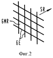
Фигура 2 показывает основную структуру решетчатой усилительной прокладки с ромбовидными ячейками решетки. Figure 2 shows the basic structure of a lattice reinforcement strip with diamond-shaped lattice cells.
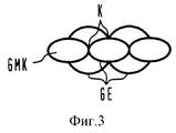
Фигура 3 показывает основную структуру решетчатой усилительной прокладки с овальными ячейками решетки. Figure 3 shows the basic structure of a trellis reinforcement strip with oval lattice cells.
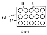
Фигура 4 показывает усилительную прокладку из плоского слоя с введенными отверстиями. Figure 4 shows a reinforcing pad of a flat layer with holes inserted.
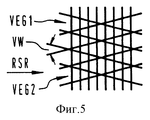
Фигура 5 показывает расположение двух смещенных под углом друг к другу решетчатых усилительных прокладок. Figure 5 shows the location of two lattice reinforced spacers offset at an angle to each other.
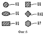
Фигура 6 показывает различные поперечные сечения для отдельных элементов решетки. Figure 6 shows various cross sections for individual lattice elements.
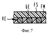
Фигуры 7-11 показывают различные возможности ламинатов. Figures 7-11 show the various possibilities of laminates.
Фигура 12 показывает оболочку с дополнительным слоем. Figure 12 shows a shell with an additional layer.
Фигура 13 показывает оболочку со становящимся оптически видимым индикатором. Figure 13 shows a shell with a becoming optically visible indicator.
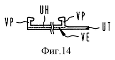
Фигура 14 показывает оболочку с замыкающими профилями. Figure 14 shows a shell with closing profiles.
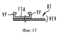
Фигура 15 показывает оболочку с замыкающими профилями и выполненной в виде ламината усилительной прокладкой. Figure 15 shows the shell with closing profiles and made in the form of a laminate reinforcing pad.
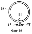
Фигура 16 показывает закрытую оболочку согласно изобретению. Figure 16 shows a closed shell according to the invention.
На фигуре 1 показана структура выполненной в виде решетки усилительной прокладки VEG. Эта структура образована из отдельных, соответственно скрещивающихся в точках пересечения K элементов решетки GE, причем здесь показаны квадратные элементы решетки GM. Усилительная прокладка VEG является усаживаемой в направлении усадки SR и неусаживаемой в продольном направлении LR или соответственно направлении оси оболочки. Обуславливающее усадку вытягивание усилительной прокладки VEG с ламинатом или без него происходит предварительно в противоположном направлении. The figure 1 shows the structure made in the form of a lattice amplification strip VEG. This structure is made up of individual lattice elements GE respectively intersecting at the intersection points K, the square elements of the GM lattice being shown here. The VEG reinforcement gasket is shrinkable in the shrink direction SR and non-shrinkable in the longitudinal direction LR or respectively the direction of the axis of the sheath. The shrinkage-causing pulling of the VEG reinforcement strip with or without laminate occurs previously in the opposite direction.
Фигура 2 показывает решетчатую усилительную прокладку VEG с ромбовидным образованием ячеек решетки GMR. Могут также применяться смещенные относительно друг друга решетчатые усилительные прокладки с одинаковыми или неодинаковыми ячейками решетки. Figure 2 shows a VEG lattice reinforcing pad with diamond-shaped GMR lattice meshing. Can also be used offset relative to each other lattice reinforcing pads with the same or different cells of the lattice.
Фигура 3 передает конструкцию усилительной прокладки с примерно круглыми или соответственно овальными ячейками решетки GMK между элементами решетки GE. В этом смысле могут последовательно соединяться в ряд только круглые элементы решетки. Можно выбирать также наложение нескольких подобных форм решетки. Figure 3 conveys the design of a reinforcing pad with approximately round or respectively oval cells of the GMK lattice between the elements of the GE lattice. In this sense, only round lattice elements can be connected in series. You can also choose to overlap several similar lattice shapes.
На фигуре 4 показан плоский усаживаемый в одном направлении плоский слой в качестве усилительной прокладки VEF, в котором введены отверстия L в равномерном расположении так, что здесь образуется квазирешетка, причем расположение отверстий L может быть выполнено также неравномерным или другой формы, например, угловатой. Находящиеся между отдельными отверстиями L перемычки материала соответствуют при этом описанным ранее элементам решетки GE, так что здесь справедливы те же отношения. Figure 4 shows a flat, one-sided shrinkable flat layer as a VEF reinforcing strip, in which holes L are introduced in a uniform arrangement so that a quasilattice is formed here, and the arrangement of holes L can also be made uneven or of another shape, for example, angular. The material bridges located between the individual holes L correspond in this case to the previously described elements of the lattice GE, so the same relations are true here.
Фигура 5 показывает расположение двух расположенных друг над другом решетчатых усилительных прокладок VEG1 и VEG2, причем обе смещены относительно их направлений усадки на угол смещения VW. Таким образом, внутри всего ламината обе усилительные прокладки образуют распределение и тем самым уменьшение напряжений в материале при возможной трещине или разрезе. Figure 5 shows the location of two lattice reinforcing strips VEG1 and VEG2 arranged one above the other, both of which are offset relative to their shrinkage directions by an offset angle VW. Thus, inside the entire laminate, both reinforcing pads form a distribution and thereby reduce stresses in the material with a possible crack or cut.
На фигуре 6 представлены различные поперечные сечения для отдельных элементов решетки GE, как, например, круглое KQ, овальное OQ, прямоугольное RQ, квадратное QQ или ромбовидное RAQ поперечные сечения. В качестве форм поперечного сечения могут быть выбраны также многоугольники или соответственно полигоны RP. Figure 6 shows various cross sections for individual elements of the GE lattice, such as, for example, round KQ, oval OQ, rectangular RQ, square QQ or diamond-shaped RAQ cross sections. Polygons or RP polygons can also be selected as cross-sectional shapes.
На следующих фигурах 7-11 представлены примеры для всего ламината оболочки, причем изображение по причинам наглядности произведено в схематичной форме. The following figures 7-11 show examples for the entire laminate, and the image for reasons of clarity is made in schematic form.
Фигура 7 показывает внешний усаживаемый плоский слой FSA, на внутренней стороне которого нанесена усаживаемая усилительная прокладка VE, причем в отдельных ячейках решетки показан наполнитель FM, которым они заполнены. Figure 7 shows the outer shrinkable flat layer FSA, on the inside of which a shrinkable reinforcing pad VE is applied, and in some cells of the lattice the FM filler is shown with which they are filled.
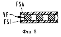
Фигура 8 показывает, что усаживаемая усилительная прокладка VE расположена между внешним плоским слоем FSA и внутренним плоским слоем FSI. Figure 8 shows that the shrinkable reinforcing pad VE is located between the outer flat layer FSA and the inner flat layer FSI.
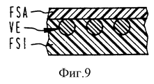
Фигура 9 показывает пример выполнения, при котором усаживаемый усилительный слой VE уложен во внутреннем плоском слое FSI, который с прочным сцеплением соединен с внешним плоским слоем FSA. Ячейки решетки или соответственно отверстия усилительной прокладки при этом заполнены материалом внутреннего плоского слоя FSI. Figure 9 shows an exemplary embodiment in which a shrinkable reinforcing layer VE is stacked in an inner plane layer FSI, which is firmly bonded to an outer plane layer FSA. The cells of the grating or, respectively, the holes of the reinforcing strip are filled with the material of the FSI inner plane layer.
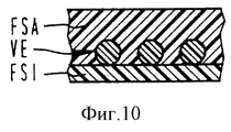
Фигура 10 показывает заделку усаживаемого усилительного слоя VE во внешнем усаживаемом плоском слое FSA, причем ячейки решетки или соответственно отверстия усилительной прокладки заполнены материалом этого плоского слоя FSA. Внутри размещен внутренний плоский слой FSI. Figure 10 shows the embedment of the shrinkable reinforcing layer VE in the outer shrinkable flat layer FSA, wherein the lattice cells or, respectively, the holes of the reinforcing pad are filled with the material of this flat FSA layer. Inside is the inner flat layer FSI.
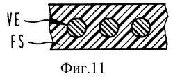
На фигуре 11 представлено, что усаживамая усилительная прокладка VE в простейшем виде вложена в единственный плоский слой FS. Figure 11 shows that the shrinkable reinforcing pad VE in its simplest form is embedded in a single flat layer FS.
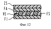
Фигура 12 показывает, что на основном ламинате оболочки могут быть размещены другие дополнительные слои ZS, причем эти дополнительные слои ZS предусмотрены для других целей. Figure 12 shows that other additional ZS layers can be placed on the main laminate of the shell, these additional ZS layers being provided for other purposes.
Так, такие дополнительные слои ZS служат, например, для оптических индикаторов, которыми показывается, достаточно ли или соответственно когда подведено достаточно тепла для процесса усадки. Такие дополнительные слои состоят, например, из термочувствительных переходных красок. So, such additional ZS layers serve, for example, for optical indicators, which show whether there is enough or accordingly when enough heat is supplied for the shrink process. Such additional layers consist, for example, of heat-sensitive transition paints.
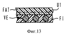
Фигура 13 показывает, что во внешнем, здесь прозрачном внешнем плоском слое FAT использован переходной индикатор UI, который, например, изменяет свой цвет, когда подведено достаточно тепла. Это изменение можно наблюдать через прозрачный плоский слой. Figure 13 shows that a transition indicator UI is used in the outer, here transparent outer flat FAT layer, which, for example, changes color when enough heat is applied. This change can be observed through a transparent flat layer.
Фигура 14 показывает, что продольные кромки оболочки снабжены замыкающими профилями VP, которыми после покрытия предмета продольные кромки удерживаются вместе в закрытом состоянии, причем это происходит с натянутой С-образной замыкающей шиной. Показано, что полный ламинат оболочки UH содержит вложенную усаживаемую усилительную прокладку VE. Вдоль продольной кромки выполнено продолжение, которое предусмотрено в качестве языка UT для перекрытия или соответственно покрытия области замыкания. Figure 14 shows that the longitudinal edges of the casing are provided with closing profiles VP, which, after covering the object, the longitudinal edges are held together in a closed state, and this happens with a stretched C-shaped locking bus. It has been shown that the full UH sheath laminate contains an embedded VE shrinkable reinforcing pad. Along the longitudinal edge, a continuation is made, which is provided as a UT language for overlapping or, respectively, covering the circuit area.
Фигура 15 показывает, наконец, что решетчатая усилительная прокладка VEV может применяться в качестве собственно ламината, то есть решетчатая усилительная прокладка снабжена, по меньшей мере, в области языка UT плоским слоем, чтобы уплотнить ячейки решетки или соответственно отверстия. Заполнение между решетчатым ламинатом VEV и внешним плоским слоем FSA происходит, как это представлено на фигурах 7-13. 15 finally shows that the VEV trellis reinforcement pad can be used as the laminate itself, that is, the trellis reinforcement pad is provided with at least a flat layer in the region of the UT tongue to seal the lattice cells or, respectively, the openings. Filling between the trellised laminate VEV and the outer flat layer FSA occurs, as shown in figures 7-13.
Фигура 16 показывает оболочку согласно изобретению в закрытом состоянии, причем становится ясным, что оба замыкающих профиля VP сведены для замыкания и удерживаются вместе не показанной здесь замыкающей шиной. Язык UT перекрывает с уплотнением продольный замок в области замыкания, причем уплотнение осуществляется с помощью покрытия слоем плавкого клея, нанесенного на внутренней стороне оболочки. Figure 16 shows the casing according to the invention in the closed state, and it becomes clear that both of the closing profiles VP are brought together for closure and are held together by the locking bus not shown here. The UT tongue overlaps with the seal a longitudinal lock in the closure region, the seal being carried out by coating with a layer of hot-melt adhesive applied on the inside of the sheath.
Далее усилительная прокладка может изготавливаться в виде экструдированной или штампованной детали; возможными являются также решетчатые структуры из соприкасающихся в одной плоскости элементов решетки, как это получается при объединении элементов застежки "молния"
Сшивку можно производить или путем высокоэнергетичного облучения, или с помощью перекисных или химических добавок (силан), причем возможна также комбинация обоих способов. Так, например, можно производить известную по себе силановую сшивку.Further, the reinforcing pad can be made in the form of an extruded or stamped part; lattice structures made of lattice elements in contact in the same plane are also possible, as is the case when combining the zipper elements
Crosslinking can be done either by high-energy irradiation, or by peroxide or chemical additives (silane), and a combination of both methods is also possible. Thus, for example, silane cross-linking known per se can be produced.
Среди прочих для термоусаживаемой оболочки пригодными являются следующие материалы, которые могут применяться как для плоских слоев, так и для усилительной прокладки:
- полиэтилен высокой плотности (HDPE);
- полиэтилен низкой плотности (LDPE);
- линейный полиэтилен низкой плотности (LLDPE);
- линейный полиэтилен низкой плотности (LLDPE) с этилен-сополимер/терполимером;
компаунд из HDPE/LDPE/LLDPE;
компаунд из этилен-сополимер/терполимера.Among others, the following materials are suitable for a heat-shrinkable sheath, which can be used for both flat layers and reinforcing strips:
- high density polyethylene (HDPE);
- low density polyethylene (LDPE);
- linear low density polyethylene (LLDPE);
- linear low density polyethylene (LLDPE) with ethylene copolymer / terpolymer;
compound from HDPE / LDPE / LLDPE;
compound of ethylene copolymer / terpolymer.
Claims (50)
Applications Claiming Priority (2)
| Application Number | Priority Date | Filing Date | Title |
|---|---|---|---|
| DE19544539.2 | 1995-11-29 | ||
| DE19544539 | 1995-11-29 |
Publications (2)
| Publication Number | Publication Date |
|---|---|
| RU96122498A RU96122498A (en) | 1999-01-27 |
| RU2159702C2 true RU2159702C2 (en) | 2000-11-27 |
Family
ID=7778731
Family Applications (1)
| Application Number | Title | Priority Date | Filing Date |
|---|---|---|---|
| RU96122498/12A RU2159702C2 (en) | 1995-11-29 | 1996-11-26 | Thermoshrinkable shell |
Country Status (11)
| Country | Link |
|---|---|
| US (1) | US5698280A (en) |
| EP (1) | EP0776753B1 (en) |
| JP (1) | JP3877242B2 (en) |
| KR (1) | KR100443763B1 (en) |
| CN (1) | CN1080194C (en) |
| AR (1) | AR004815A1 (en) |
| AT (1) | ATE212900T1 (en) |
| DE (1) | DE59608700D1 (en) |
| ES (1) | ES2172618T3 (en) |
| IN (1) | IN191391B (en) |
| RU (1) | RU2159702C2 (en) |
Families Citing this family (6)
| Publication number | Priority date | Publication date | Assignee | Title |
|---|---|---|---|---|
| AUPQ746100A0 (en) * | 2000-05-05 | 2000-06-08 | Collier, Peter | Improvements in building blocks |
| KR20030017718A (en) * | 2001-08-22 | 2003-03-04 | 유기봉 | Heat shrinkable sleeve and the manufacturing method of it |
| DE202008001748U1 (en) | 2008-02-07 | 2008-04-03 | Ccs Technology Inc., Wilmington | Heat-shrinkable cable sleeve for protecting at least one connection point between cables |
| DE202008009118U1 (en) | 2008-07-08 | 2009-02-19 | CCS Technology, Inc., Wilmington | Heat-shrinkable cable sleeve |
| US8028837B2 (en) * | 2008-12-18 | 2011-10-04 | Kimberly-Clark Worldwide, Inc. | Break-open package with shaped die cut for storing and dispensing substrates |
| US10998651B2 (en) | 2019-05-22 | 2021-05-04 | Nvent Services Gmbh | Flame-resistant heat shrink assemblies for trace heating cables |
Family Cites Families (19)
| Publication number | Priority date | Publication date | Assignee | Title |
|---|---|---|---|---|
| DE1704517A1 (en) * | 1968-01-03 | 1971-01-28 | Bemberg Ag | Composite film with a reinforcing insert consisting of a lattice-shaped surface structure |
| JPS5211637B1 (en) * | 1970-06-09 | 1977-04-01 | ||
| DE7501913U (en) | 1974-01-23 | 1975-07-31 | Nv Raychem Sa | Resettable, tubular connection sleeve |
| GB1497051A (en) * | 1974-01-23 | 1978-01-05 | Raychem Sa Nv | Reinforced heat-recoverable articles and their uses |
| DE3150544A1 (en) * | 1981-12-21 | 1983-06-30 | Siemens AG, 1000 Berlin und 8000 München | Insulating, waterproof cable end insulation |
| US4631098A (en) | 1983-01-06 | 1986-12-23 | Raychem Limited | Heat-recoverable article |
| DE3307567A1 (en) * | 1983-03-03 | 1984-09-06 | Siemens AG, 1000 Berlin und 8000 München | HEAT RECOVERABLE OBJECT |
| US4554202A (en) * | 1983-07-08 | 1985-11-19 | Showa Denko Kabushiki Kaisha | Packaging cloth |
| US4952437A (en) * | 1987-07-15 | 1990-08-28 | Firma Rxs Schrumpftechnik-Garnituren Gmbh | Heat-shrinkable sleeve |
| US4929477A (en) | 1987-07-15 | 1990-05-29 | Firma Rxs Schrumpftechnik-Garnituren Gmbh | Heat-shrinkable sleeve and the process for the production thereof |
| AU630217B2 (en) * | 1989-08-10 | 1992-10-22 | Shaw Industries Ltd | Heat shrinkable protective sheets and method for their manufacture |
| US5134000A (en) * | 1989-08-10 | 1992-07-28 | Shaw Industries Ltd. | Heat shrinkable protective sheets and methods for their manufacture |
| DE59009800D1 (en) * | 1990-08-20 | 1995-11-23 | Rxs Schrumpftech Garnituren | Composite covering made of at least one heat-shrinkable film with reinforcement and process for its production. |
| EP0525519B1 (en) * | 1991-07-22 | 1996-12-18 | RXS Kabelgarnituren Gesellschaft mit beschränkter Haftung | Heat-shrinkable composite sheet |
| DE4140273C2 (en) * | 1991-12-06 | 1995-08-17 | Stewing Nachrichtentechnik | Heat-sensitive surface coating for heat-shrinkable products, especially shrink sleeves made of thermoplastic for cable sleeves |
| DE4200251A1 (en) * | 1992-01-08 | 1993-07-15 | Kabelmetal Electro Gmbh | High tear strength heat-shrink material with high flame resistance - consists of main crosslinked e.g. polyethylene@ reinforced with incorporated non stretch of glass warp threads and elastomer weft filaments |
| DE9208661U1 (en) * | 1992-06-27 | 1992-09-10 | Kabelmetal Electro Gmbh, 3000 Hannover, De | |
| US5302428A (en) * | 1992-09-29 | 1994-04-12 | Shaw Industries Ltd. | Multi-layer wraparound heat shrink sleeve |
| DE59401684D1 (en) * | 1993-04-20 | 1997-03-13 | Rxs Schrumpftech Garnituren | Heat shrinkable cable sleeve |
-
1996
- 1996-11-05 ES ES96117690T patent/ES2172618T3/en not_active Expired - Lifetime
- 1996-11-05 AT AT96117690T patent/ATE212900T1/en not_active IP Right Cessation
- 1996-11-05 EP EP96117690A patent/EP0776753B1/en not_active Expired - Lifetime
- 1996-11-05 DE DE59608700T patent/DE59608700D1/en not_active Expired - Lifetime
- 1996-11-22 US US08/754,161 patent/US5698280A/en not_active Expired - Lifetime
- 1996-11-26 IN IN2036CA1996 patent/IN191391B/en unknown
- 1996-11-26 RU RU96122498/12A patent/RU2159702C2/en not_active IP Right Cessation
- 1996-11-29 CN CN96121919A patent/CN1080194C/en not_active Expired - Fee Related
- 1996-11-29 JP JP32019696A patent/JP3877242B2/en not_active Expired - Fee Related
- 1996-11-29 KR KR1019960059372A patent/KR100443763B1/en not_active IP Right Cessation
- 1996-11-29 AR ARP960105424A patent/AR004815A1/en unknown
Also Published As
| Publication number | Publication date |
|---|---|
| ES2172618T3 (en) | 2002-10-01 |
| IN191391B (en) | 2003-11-29 |
| JPH09174723A (en) | 1997-07-08 |
| US5698280A (en) | 1997-12-16 |
| KR970025940A (en) | 1997-06-24 |
| ATE212900T1 (en) | 2002-02-15 |
| EP0776753A3 (en) | 1998-04-08 |
| KR100443763B1 (en) | 2004-09-30 |
| CN1080194C (en) | 2002-03-06 |
| CN1158789A (en) | 1997-09-10 |
| EP0776753B1 (en) | 2002-02-06 |
| JP3877242B2 (en) | 2007-02-07 |
| DE59608700D1 (en) | 2002-03-21 |
| EP0776753A2 (en) | 1997-06-04 |
| AR004815A1 (en) | 1999-03-10 |
Similar Documents
| Publication | Publication Date | Title |
|---|---|---|
| FI93408B (en) | Retractable cuff and joint between elongated bodies | |
| ES2084088T5 (en) | ARTICLE RECOVERABLE BY HEAT. | |
| AU603234B2 (en) | A heat-shrinkable sleeve | |
| US4929477A (en) | Heat-shrinkable sleeve and the process for the production thereof | |
| KR102082921B1 (en) | Sheet for prevention of water and root, construction method thereof | |
| JPH05254016A (en) | Recoverable composite structure | |
| RU2159702C2 (en) | Thermoshrinkable shell | |
| KR100742215B1 (en) | Pipe joint | |
| CA2702176A1 (en) | Antislip sheet material with twisted tapes | |
| US4952438A (en) | Heat-shrinkable envelope | |
| JPH04261828A (en) | Composite coating and manufacture thereof | |
| RU96122498A (en) | Heat Shrinkable Shell | |
| US5250332A (en) | Heat-shrinkable envelope having low-tearing susceptibility | |
| KR0140803B1 (en) | Heat shirinkable sleeve | |
| JP3295698B2 (en) | Waterproof sheet protection mat | |
| KR940003748B1 (en) | Heat shrinkable sleeve | |
| RU1788806C (en) | Multilayer hydraulic deal protection material | |
| KR20030017716A (en) | Sealing product with heatshrink | |
| KR19980021660A (en) | Heat Shrink Sleeves for Protecting Communication Cable Connections | |
| JPH0841878A (en) | High-strength net body |
Legal Events
| Date | Code | Title | Description |
|---|---|---|---|
| PC4A | Invention patent assignment |
Effective date: 20051110 |
|
| MM4A | The patent is invalid due to non-payment of fees |
Effective date: 20131127 |