RU2159016C2 - Method and device for phase angle detection - Google Patents
Method and device for phase angle detection Download PDFInfo
- Publication number
- RU2159016C2 RU2159016C2 RU94034112/09A RU94034112A RU2159016C2 RU 2159016 C2 RU2159016 C2 RU 2159016C2 RU 94034112/09 A RU94034112/09 A RU 94034112/09A RU 94034112 A RU94034112 A RU 94034112A RU 2159016 C2 RU2159016 C2 RU 2159016C2
- Authority
- RU
- Russia
- Prior art keywords
- phase angle
- angle
- values
- polar zone
- polar
- Prior art date
Links
Images


Classifications
-
- H—ELECTRICITY
- H04—ELECTRIC COMMUNICATION TECHNIQUE
- H04N—PICTORIAL COMMUNICATION, e.g. TELEVISION
- H04N11/00—Colour television systems
- H04N11/06—Transmission systems characterised by the manner in which the individual colour picture signal components are combined
- H04N11/18—Transmission systems characterised by the manner in which the individual colour picture signal components are combined using simultaneous and sequential signals, e.g. SECAM-system
- H04N11/186—Decoding means therefor
Abstract
Description
Настоящее изобретение относится к обработке видеосигналов и, в частности, к модуляции цветоразностных сигналов. The present invention relates to the processing of video signals and, in particular, to the modulation of color difference signals.
В цветоразностных системах, таких как система цветного телевидения СЕКАМ, цветоразностные сигналы кодируют с использованием частотно-уплотняющей (ЧМ) модуляции. Квадратурная демодуляция такого цветоразностного сигнала дает результат в декартовых координатах, которые нужно преобразовать в полярные координаты для определения фазового угла, а значит - и частоты. Если декартовы координаты - это U и V, то фазовый угол, который необходимо вычислить, составляет
θ = arctg(V/U).In color difference systems, such as the SECAM color television system, color difference signals are encoded using frequency division multiplexing (FM) modulation. Quadrature demodulation of such a color difference signal gives the result in Cartesian coordinates, which must be converted to polar coordinates to determine the phase angle, and hence the frequency. If the Cartesian coordinates are U and V, then the phase angle that needs to be calculated is
θ = arctg (V / U).
В цифровой системе эта функция может быть выполнена, например, с помощью таблицы преобразования по закону арктангенса, принимающей выходной сигнал с умножителя, имеющего V в качестве одного входного сигнала, а в качестве другого входного сигнала - выходной сигнал таблицы преобразования, получающей обратную величину U. Расчет, как в любой цифровой системе, будет включать ошибки квантования. Если эти ошибки недопустимы в конкретном приложении, то стандартное решение - увеличить количество битов в цифровой области. Однако это, вообще говоря, значительно дороже. In a digital system, this function can be performed, for example, using the arc tangent transformation table, which receives the output signal from a multiplier having V as one input signal, and as the other input signal, the output signal of the conversion table, receiving the inverse value U. The calculation, as in any digital system, will include quantization errors. If these errors are unacceptable in a particular application, then the standard solution is to increase the number of bits in the digital domain. However, this, generally speaking, is much more expensive.
Задача настоящего изобретения состоит в том, чтобы обеспечить улучшенные средства для определения фазового угла при демодуляции цветоразностных сигналов, что дает общее уменьшение ошибок квантования без увеличения количества битов. An object of the present invention is to provide improved means for determining the phase angle when demodulating color difference signals, which provides an overall reduction in quantization errors without increasing the number of bits.
Соответственно, настоящее изобретение заключается в одном аспекте в устройстве для определения фазового угла при демодуляции цветоразностных сигналов U и V, которое содержит распознающее средство для распознавания полярной зоны минимальной ошибки квантования, отображающее средство для преобразования значений U и V в указанную полярную зону и вычислительное средство для вычисления истинного угла по преобразованным значениям U и V. Accordingly, the present invention consists in one aspect in a device for determining a phase angle when demodulating color difference signals U and V, which comprises recognition means for recognizing a polar zone of a minimum quantization error, displaying means for converting U and V values to said polar zone and computing means for calculating the true angle from the converted values of U and V.
Теперь изобретение будет описано на примере со ссылками на прилагаемые чертежи, на которых
фиг. 1 - блок-схема, иллюстрирующая подход из известного уровня техники,
фиг. 2 - фазовая диаграмма в координатах UV, на которой идентифицированы полярные зоны,
фиг. 3 - блок-схема средств обработки видеосигналов, соответствующих настоящему изобретению,
фиг. 4 - блок-схема, иллюстрирующая альтернативный конкретный вариант осуществления настоящего изобретения,
фиг. 5 - блок-схема, иллюстрирующая модификацию к устройству, показанному на фиг. 4, и
фиг. 6 - блок-схема, иллюстрирующая еще один конкретный вариант осуществления настоящего изобретения.The invention will now be described by way of example with reference to the accompanying drawings, in which
FIG. 1 is a flowchart illustrating a prior art approach,
FIG. 2 is a phase diagram in UV coordinates on which polar zones are identified,
FIG. 3 is a block diagram of video processing means according to the present invention,
FIG. 4 is a block diagram illustrating an alternative specific embodiment of the present invention,
FIG. 5 is a block diagram illustrating a modification to the device shown in FIG. 4, and
FIG. 6 is a block diagram illustrating another specific embodiment of the present invention.
Обращаясь сначала к фиг. 1, отмечается, что здесь показан подход к аппаратному обеспечению для реализации функции
θ = arctg(V/U).Turning first to FIG. 1, it is noted that a hardware approach for implementing a function is shown here.
θ = arctg (V / U).
Первая таблица 10 преобразования настроена на получение обратной величины U. Затем умножитель 12 формирует частное V/U, причем функция арктангенса формируется в дополнительной таблице 14 преобразования, обеспечивающей выходной сигнал θ. The first conversion table 10 is configured to obtain the reciprocal of U. Then, the multiplier 12 generates a quotient V / U, wherein the arc tangent function is generated in an additional conversion table 14 providing the output signal θ.
При конкретном уровне квантования можно моделировать отклик этого аппаратного обеспечения и исходя из него получать значение ошибки между "действительным" и "расчетным" значениями θ. Установлено, что ошибка остается в пределах относительно узкой полосы для фазового угла менее 45o. Если рассматривается полный диапазон фазового угла, то диапазон, на котором эта малая ошибка квантовая обнаруживается, составляет -45o < θ< +45o. Вне этого квадранта ошибка квантования может быть значительно больше.At a specific quantization level, one can simulate the response of this hardware and proceed from it to obtain the error value between the “real” and “calculated” θ values. It is established that the error remains within a relatively narrow strip for a phase angle of less than 45 o . If we consider the full range of the phase angle, then the range over which this small quantum error is detected is -45 o <θ <+45 o . Outside of this quadrant, the quantization error can be much larger.
Обращаясь к фиг. 2, отмечается, что здесь представлена диаграмма в координатах UV, на которой квадрант минимальной ошибки квантования показан как Q0, а три других квадранта или полярных зоны - Q1, Q2 и Q3 могут быть распознаны.Turning to FIG. 2, it is noted that a UV coordinate diagram is presented here, in which the quadrant of the minimum quantization error is shown as Q 0 , and the other three quadrants or polar zones - Q 1 , Q 2 and Q 3 can be recognized.
Согласно настоящему изобретению, входные значения U и V сначала обрабатываются для определения того, в каком квадранте лежит результирующий вектор. Если этот вектор лежит в квадранте Q0, осуществляется непосредственное вычисление θ с помощью, например, подхода, показанного на фиг. 1. Если вектор лежит в любом другом квадранте, сначала проводят преобразование для того, чтобы перевести этот вектор в квадрант Q0. Затем осуществляется вычисление θ, по существу, с помощью подхода, показанного на фиг. 1, но с результатом, модифицированным с учетом преобразования, которое уже сделано.According to the present invention, the input values U and V are first processed to determine in which quadrant the resulting vector lies. If this vector lies in the quadrant Q 0 , θ is directly calculated using, for example, the approach shown in FIG. 1. If the vector lies in any other quadrant, a transformation is first performed in order to translate this vector into the quadrant Q 0 . Then, θ is calculated essentially using the approach shown in FIG. 1, but with a result modified to reflect the transformation that has already been done.
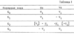
Обращаясь теперь к фиг. 3, можно увидеть, что составляющие U и V сначала подаются в блок 20, который определяет, какая из четырех полярных зон содержит результирующий вектор. Результат этой оценки вместе со значениями U и V подается в преобразующий блок 22, который выдает преобразованные значения U и V. Сущность этого преобразования представлена в таблице 1, где Ui и Vi представляют входные значения, a U0 и V0 представляют преобразованные выходные значения (см. табл. 1).Turning now to FIG. 3, it can be seen that the components U and V are first supplied to
Таблица 24 преобразования осуществляет инверсию, а умножитель 26 выдает частное V0/U0. Таблица 28 преобразования по закону арктангенса осуществляет две отдельные функции. Во-первых, вычисляется угол θt с использованием прямой функции арктангенса на этом частном. Во вторых, проводится компенсация для преобразования. Для этого таблица 28 преобразования принимает в качестве второй адресной линии результат оценки, проведенной в блоке 20. Таким образом, например, если оценено, что вектор лежит в зоне Q1, истинный угол θ должен быть получен путем прибавления 90o (в подходящих блоках) к углу, непосредственно вычисленному с помощью функции арктангенса.The conversion table 24 performs the inversion, and the
В этом изобретении можно указать дополнительное преимущество. Два этапа определения квадранта, в котором лежит вектор, и последующего вычисления промежуточного угла внутри этой зоны обеспечивают соответственно грубое и точное приближение к правильному значению θ. При точном приближении можно полностью использовать количество имеющихся битов цифровой обработки. Соответственно, результат достигается с точностью, для которой в противном случае потребовались бы два дополнительных бита цифровой обработки. An additional advantage may be indicated in this invention. Two stages of determining the quadrant in which the vector lies, and then calculating the intermediate angle inside this zone, respectively, provide a rough and accurate approximation to the correct value of θ. With an exact approximation, the number of available digital processing bits can be fully utilized. Accordingly, the result is achieved with accuracy, which would otherwise require two additional bits of digital processing.
Теперь будет описан дополнительный конкретный вариант осуществления изобретения со ссылками на фиг. 4. Этот конкретный вариант осуществления предназначен для обеспечения угла между последующими векторами UV. В других отношениях его функция аналогична функции конкретного варианта осуществления, показанного на фиг. 3, хотя проиллюстрированы минимальные изменения. An additional specific embodiment of the invention will now be described with reference to FIGS. 4. This particular embodiment is intended to provide an angle between subsequent UV vectors. In other respects, its function is similar to that of the specific embodiment shown in FIG. 3, although minimal changes are illustrated.
Значения U и V подаются в блок 40 квадранта, который служит для распознавания квадранта, в котором лежит вектор. Как и прежде, квадрант Q0 определяется как от +45 до -45o. Идентификатор квадранта вместе со значениями U и V, задержанными на соответствующее время в согласующих задержку блоках 42 и 44 соответственно, подаются в отображающий блок 46. Он выполняет ту же функцию, что и блок 20 на фиг. 3, и поэтому не требует дальнейшего описания.The values of U and V are supplied to the
Выходной сигнал U из отображающего блока 46 подается через таблицу 48 преобразования 1/U в умножитель 50, который также принимает выходной сигнал V из отображающего блока 46, подаваемый через согласующий задержку блок 52. Выходной сигнал умножителя 50 служит входным сигналом в таблицу 54 преобразования по закону арктангенса. Выходной сигнал этой таблицы преобразования суммируется в сумматоре 56 с угловым смещением, создаваемым в генераторе 58 смещения по информации квадранта, выдаваемой блоком 40 квадранта. Как только что описывалось, это устройство отличается от показанного на фиг. 3 тем, что угол смещения суммируется с выходным сигналом таблицы преобразования по закону арктангенса (чтобы избежать использования таблицы преобразования со сдвоенными входами), и тем, что четко показаны согласующие задержку блоки. The output signal U from the
Для того, чтобы вычислить угол между двумя последовательными векторами, вычитающий блок 60 принимает текущее значение угла из сумматора 56 и предыдущее значение угла через блок задержки 62. Таким образом, угол между векторами обеспечивается в качестве выходного сигнала. In order to calculate the angle between two successive vectors, the
Авторы настоящего изобретения признали, что устройство, показанное на фиг. 4, можно упростить - с последующим снижением затрат на аппаратное обеспечение - при тех обстоятельствах, когда имеется корреляция между последующими векторами. Таким образом, если можно допустить, что угол, разделяющий любые два последующие вектора, будет по величине меньше или равен 45o, то можно достичь такой же точности с меньшим количеством битов.The inventors have recognized that the device shown in FIG. 4 can be simplified — with a subsequent reduction in hardware costs — in those circumstances where there is a correlation between subsequent vectors. Thus, if it can be assumed that the angle dividing any two subsequent vectors will be less than or equal to 45 o in size, then the same accuracy can be achieved with fewer bits.
Чтобы проиллюстрировать эту точку зрения, приводится пример (см. табл. 2). To illustrate this point of view, an example is given (see table. 2).
Можно увидеть, что при отображающей операции требуется смещение 90o, чтобы отобразить вектор 1 в квадрант Q0, а смещение для вектора 2 составляет 180o. Следуя подходу, показанному на фиг. 4, можно вывести угол между векторами следующим образом:
(Отображенный угол 2 + Смещение 2) - (Отображенный угол 1 + Смещение 1), или
(-32o + 180o)- (+43o + 90o) = 15o.You can see that during the mapping operation, an offset of 90 ° is required to map
(Mapped
(-32 o + 180 o ) - (+43 o + 90 o ) = 15 o .
Значения отображенного угла, находящиеся между +45o и -45o, можно представить в 10 битах; значения смещения 90o, 180o или 270o потребуют, однако, 13 бит. Поэтому последующая обработка должна потребовать разрешения в 13 бит с вытекающими отсюда более жесткими требованиями к аппаратному обеспечению.Values of the displayed angle between +45 o and -45 o can be represented in 10 bits; offset values of 90 ° , 180 ° or 270 ° will require, however, 13 bits. Therefore, subsequent processing should require a resolution of 13 bits with the consequent more stringent hardware requirements.
Согласно предпочтительному признаку этого изобретения, если можно сделать допущение относительно максимальной амплитуды угла между последовательными векторами, информация об угле смещения отбрасывается. Таким образом, если взять предыдущий пример, угол выводится так:
(Отображенный угол 2)-(Отображенный угол 1), или
(-32o)-(+43o) = -75o,
Это значит, что согласно сделанному допущению получен неверный результат, и поэтому применяется поправка на 90o.According to a preferred feature of this invention, if an assumption can be made regarding the maximum amplitude of the angle between successive vectors, information about the angle of displacement is discarded. Thus, if we take the previous example, the angle is displayed like this:
(Mapped angle 2) - (Mapped angle 1), or
(-32 o ) - (+ 43 o ) = -75 o ,
This means that according to the assumption made, an incorrect result was obtained, and therefore a 90 o correction is applied.
Если гарантируется, что выходной сигнал таблицы преобразования по закону арктангенса полностью использует числовой диапазон 10 бит (при -45o, представленных как -512, и +45o, представленных как +512), то этот результат может быть достигнут простым усечением. Таким образом, продолжая тот же пример, -75o, представленные как 512* - 75/45= -853 или OxFCAB в шестикратном усечении до 10 бит дает OxAB = 171 или 45o • 171/512 = 15o.If it is guaranteed that the output of the conversion table according to the law of arc tangent fully utilizes the numerical range of 10 bits (at -45 o represented as -512 and +45 o represented as +512), this result can be achieved by simple truncation. Thus, continuing the same example, -75 o , represented as 512 * - 75/45 = -853 or OxFCAB six times truncated to 10 bits gives OxAB = 171 or 45 o • 171/512 = 15 o .
Поэтому при требуемом разрешении не более 10 бит можно применять упрощенную структуру программного обеспечения, такую, как показанная на фиг. 5. Выходной сигнал из таблицы 56 преобразования по закону арктангенса проходит непосредственно в вычитающий блок 60 и далее через блок задержки 62. Блок 58 смещения угла и сумматор 56 исключаются. Therefore, with the required resolution of not more than 10 bits, a simplified software structure, such as that shown in FIG. 5. The output signal from the conversion table 56 according to the law of arc tangent passes directly to the subtracting
В дополнительном конкретном примере осуществления изобретения векторы отображаются не в соответствии с четырьмя квадрантами, а в соответствии с восемью секторами. Преимущество этого устройства, как станет ясно, состоит в том, что обработка ограничена положительными значениями U и V. Один избыточный бит разрешения усиливается без необходимости оперировать двузначными дополнительными числами. In a further specific embodiment, the vectors are displayed not in accordance with four quadrants, but in accordance with eight sectors. The advantage of this device, as it becomes clear, is that the processing is limited to positive values of U and V. One redundant resolution bit is amplified without the need to operate with two-digit additional numbers.
Обращаясь теперь к фиг. 6, отмечается, что значения U и V подаются в секторный блок 70, который служит для распознавания сектора, в котором лежит вектор. Сектор S1 определяется как от 0 до 45o; сектор S2 определяется как от 0 до 90o, и так далее. Идентификатор вектора вместе со значениями U и V, задержанными на подходящее время в согласующих задержку блоках 72 и 74 соответственно, подаются в отображающий блок 76. Он выполняет такую функцию (где выражение "велич. U" относится к величине U и т.п.) (см. табл. 3).Turning now to FIG. 6, it is noted that the values of U and V are supplied to a sector block 70, which serves to recognize the sector in which the vector lies. Sector S 1 is defined as from 0 to 45 o ; sector S 2 is defined as from 0 to 90 o , and so on. The vector identifier, together with the values of U and V, delayed by a suitable time in the delay matching blocks 72 and 74, respectively, are supplied to the
Следует признать, что в то время, как предыдущая схема для отображения в квадрант Q0 приводила к положительным или отрицательным значениям V и только положительным значениями U, это отображение в сектор S будет давать только положительные значения U и V. Этими значениями можно оперировать с более высоким разрешением, чем в случае, если бы пришлось приспосабливать и отрицательные числа.It should be recognized that while the previous scheme for mapping into the quadrant Q 0 led to positive or negative values of V and only positive values of U, this mapping to sector S will give only positive values of U and V. These values can be operated on with more higher resolution than if you had to adapt negative numbers as well.
Выходной сигнал U из отображающего блока 76 подается через таблицу 78 преобразования 1/U в умножитель 80, который также принимает выходной сигнал V из отображающего блока 76, подаваемый через согласующий задержку блок 82. Выходной сигнал умножителя 80 служит входным сигналом в таблицу 84 преобразования по закону арктангенса. Эта таблица принимает в качестве дополнительного одного входного бита знак величины из секторного блока 70. Чтобы вычислить угол между последующими векторами, вычитающий блок 88 принимает текущее значение угла из таблицы 84 преобразования и значение предыдущего угла через блок задержки 86. Таким образом, угол между векторами выдается в качестве выходного сигнала. The output signal U from the
Следует понять, что это изобретение описано только на примерах, и возможны многие дополнительные модификации в рамках объема притязаний. В той степени, в какой описанные конкретные варианты осуществления включают в себя различные предпочтительные признаки, будут возможны приложения, в которых будут приемлемы другие совокупности этих признаков. It should be understood that this invention is described only by examples, and many additional modifications are possible within the scope of the claims. To the extent that the specific embodiments described include various preferred features, applications will be possible in which other combinations of these features are acceptable.
Надписи на чертежах
10 - ТП (таблица преобразования) 1/U; 14 - ТП по закону арктангенса
Фиг. 3:
20 - оценка полярной зоны (0, 1, 2 или 3); 22 - преобразование цветоразностных сигналов при необходимости; 24 - ТП 1/U; 28 - ТП по закону арктангенса
Фиг. 4:
40 - распознавание квадранта; 42 - задержка данных; 44 - задержка данных; 46 - отображение U+V; 48 - ТП 1/U; 52 - задержка данных; 54 - ТП по закону арктангенса; 58 - выбор смещения угла; 62 - задержка данных
Фиг. 6:
70 - распознавание сектора; 72 - задержка данных; 74 - задержка данных; 76 - отображение U + V; 78 - ТП 1/U; 82 - задержка данных; 84 - ТП по закону арктангенса; 86 - задержка данныхThe inscriptions on the drawings
10 - TP (conversion table) 1 / U; 14 - TP according to the law of arctangent
FIG. 3:
20 - assessment of the polar zone (0, 1, 2 or 3); 22 - conversion of color difference signals, if necessary; 24 -
FIG. 4:
40 - quadrant recognition; 42 - data delay; 44 - data delay; 46 - mapping U + V; 48 -
FIG. 6:
70 - sector recognition; 72 - data delay; 74 - data delay; 76 - mapping U + V; 78 -
Claims (10)
θ = arctg (V/U).4. The device according to any one of the preceding claims 1 to 3, characterized in that said computing means provides the function:
θ = arctg (V / U).
θ = arctg (V/U).10. The method according to claim 9, characterized in that the calculation step provides a function
θ = arctg (V / U).
Applications Claiming Priority (3)
| Application Number | Priority Date | Filing Date | Title |
|---|---|---|---|
| GB939319728A GB9319728D0 (en) | 1993-09-24 | 1993-09-24 | Video signal processing |
| GB9319728.3 | 1993-09-24 | ||
| GB9319728 | 1993-09-24 |
Publications (2)
| Publication Number | Publication Date |
|---|---|
| RU94034112A RU94034112A (en) | 1996-07-20 |
| RU2159016C2 true RU2159016C2 (en) | 2000-11-10 |
Family
ID=10742474
Family Applications (1)
| Application Number | Title | Priority Date | Filing Date |
|---|---|---|---|
| RU94034112/09A RU2159016C2 (en) | 1993-09-24 | 1994-09-23 | Method and device for phase angle detection |
Country Status (3)
| Country | Link |
|---|---|
| FR (1) | FR2711471B1 (en) |
| GB (2) | GB9319728D0 (en) |
| RU (1) | RU2159016C2 (en) |
Families Citing this family (2)
| Publication number | Priority date | Publication date | Assignee | Title |
|---|---|---|---|---|
| US7920658B2 (en) | 2005-03-10 | 2011-04-05 | Qualcomm Incorporated | Efficient method to compute one shot frequency estimate |
| CN110568415B (en) * | 2019-07-22 | 2022-04-08 | 广东工业大学 | Signal detection method based on Arctan function under Gaussian mixture model |
Family Cites Families (6)
| Publication number | Priority date | Publication date | Assignee | Title |
|---|---|---|---|---|
| FR2469824A1 (en) * | 1979-11-14 | 1981-05-22 | Thomson Csf | METHOD FOR DEMODULATING A FREQUENCY MODULATED SIGNAL AND DEMODULATORS IMPLEMENTING THIS METHOD |
| FR2488755A2 (en) * | 1980-08-13 | 1982-02-19 | Thomson Csf | METHOD FOR DEMODULATING A FREQUENCY MODULATED SIGNAL AND DEMODULATORS USING THE SAME |
| FR2535462A1 (en) * | 1982-10-29 | 1984-05-04 | Labo Electronique Physique | DIGITAL CIRCUIT FOR MEASURING THE INSTANTANEOUS FREQUENCY OF A MODULATED OR NON-FREQUENCY SIGNAL, AND A TELEVISION OR RADIO RECEIVER EQUIPPED WITH SUCH A CIRCUIT |
| US4710892A (en) * | 1984-10-29 | 1987-12-01 | Rca Corporation | Phase calculation circuitry in digital television receiver |
| US4675882A (en) * | 1985-09-10 | 1987-06-23 | Motorola, Inc. | FM demodulator |
| JPH01151307A (en) * | 1987-12-08 | 1989-06-14 | Toshiba Corp | Digital fm demodulator |
-
1993
- 1993-09-24 GB GB939319728A patent/GB9319728D0/en active Pending
-
1994
- 1994-09-23 FR FR9411387A patent/FR2711471B1/en not_active Expired - Fee Related
- 1994-09-23 GB GB9419281A patent/GB2282296B/en not_active Expired - Lifetime
- 1994-09-23 RU RU94034112/09A patent/RU2159016C2/en not_active IP Right Cessation
Also Published As
| Publication number | Publication date |
|---|---|
| RU94034112A (en) | 1996-07-20 |
| GB9419281D0 (en) | 1994-11-09 |
| GB9319728D0 (en) | 1993-11-10 |
| GB2282296B (en) | 1997-11-05 |
| GB2282296A (en) | 1995-03-29 |
| FR2711471B1 (en) | 1997-04-11 |
| FR2711471A1 (en) | 1995-04-28 |
Similar Documents
| Publication | Publication Date | Title |
|---|---|---|
| US3956623A (en) | Digital phase detector | |
| US4868497A (en) | Determining angular velocity from two quadrature signals by squaring the derivative of each signal and taking the square root of the sum | |
| JPS62143527A (en) | In-phase synthesizing system | |
| EP0692867B1 (en) | FM modulation circuit and method | |
| US4710892A (en) | Phase calculation circuitry in digital television receiver | |
| RU2159016C2 (en) | Method and device for phase angle detection | |
| US5504453A (en) | Method and device for estimating phase error | |
| KR950005160B1 (en) | Integrated digital fm discriminator | |
| US3670251A (en) | System for demodulating an amplitude-modulated telegraphic wave or waves | |
| JPH0469088A (en) | Method of detection of rotor position | |
| JP3452556B2 (en) | Encoder signal processing apparatus and method | |
| JP3881590B2 (en) | Phase detection circuit and phase detection method | |
| JPH0638663B2 (en) | Clock generation circuit for digital television signal processor | |
| JPS63223523A (en) | Synchrous digital converter | |
| JP2823724B2 (en) | FM demodulator | |
| JPH05172872A (en) | Digital phase detecting device | |
| RU93029576A (en) | METHOD FOR CONVERTING THE SHAFT TURN ANGLE IN THE CODE | |
| JPH01195322A (en) | Angle detecting device | |
| JPH08114464A (en) | Signal converter circuit | |
| JPH05267968A (en) | Amplitude limit processing circuit | |
| JPS6394707A (en) | Arc tangent type fm demodulator | |
| JPH0720253B2 (en) | Color difference signal switching circuit | |
| JPS6085650A (en) | Method for correcting carrier shift | |
| JPS63223524A (en) | Synchrous digital converter | |
| JPH0526922A (en) | Digital phase detector |
Legal Events
| Date | Code | Title | Description |
|---|---|---|---|
| MM4A | The patent is invalid due to non-payment of fees |
Effective date: 20030924 |