RU2158373C1 - Turbocharged v-type internal combustion engine - Google Patents
Turbocharged v-type internal combustion engine Download PDFInfo
- Publication number
- RU2158373C1 RU2158373C1 RU99106776/06A RU99106776A RU2158373C1 RU 2158373 C1 RU2158373 C1 RU 2158373C1 RU 99106776/06 A RU99106776/06 A RU 99106776/06A RU 99106776 A RU99106776 A RU 99106776A RU 2158373 C1 RU2158373 C1 RU 2158373C1
- Authority
- RU
- Russia
- Prior art keywords
- receiver
- intake
- blocks
- turbocompressor
- compressor
- Prior art date
Links
Images

Classifications
-
- Y—GENERAL TAGGING OF NEW TECHNOLOGICAL DEVELOPMENTS; GENERAL TAGGING OF CROSS-SECTIONAL TECHNOLOGIES SPANNING OVER SEVERAL SECTIONS OF THE IPC; TECHNICAL SUBJECTS COVERED BY FORMER USPC CROSS-REFERENCE ART COLLECTIONS [XRACs] AND DIGESTS
- Y02—TECHNOLOGIES OR APPLICATIONS FOR MITIGATION OR ADAPTATION AGAINST CLIMATE CHANGE
- Y02T—CLIMATE CHANGE MITIGATION TECHNOLOGIES RELATED TO TRANSPORTATION
- Y02T10/00—Road transport of goods or passengers
- Y02T10/10—Internal combustion engine [ICE] based vehicles
- Y02T10/12—Improving ICE efficiencies
Landscapes
- Supercharger (AREA)
Abstract
Description
Изобретение относится к области двигателестроения и может найти применение в конструкции многоцилиндровых V-образных ДВС с турбонаддувом. The invention relates to the field of engine manufacturing and can find application in the design of multi-cylinder V-shaped internal combustion engines with turbocharging.
Известны V-образные двигатели внутреннего сгорания с турбонаддувом (см. [1] А.с. N 543773, F 02 B 37/00; [2] А.с. N 1590586, F 02 B 37/02). Недостатком таких двигателей являются увеличенные габаритные размеры из-за наличия одного или нескольких турбокомпрессоров, размещаемых за пределами габаритов собственно двигателя. V-shaped turbocharged internal combustion engines are known (see [1] A.S. N 543773, F 02 B 37/02; [2] A.S. N 1590586, F 02 B 37/02). The disadvantage of such engines is the increased overall dimensions due to the presence of one or more turbocompressors located outside the dimensions of the engine itself.
Указанный недостаток частично устранен в устройстве для наддува двигателя внутреннего сгорания ([3] А.с. 1296735, F 02 B 37/00). This drawback is partially eliminated in the device for boosting the internal combustion engine ([3] A.S. 1296735, F 02 B 37/00).
В рассматриваемом устройстве турбокомпрессор частично размещен в V-образном развале блока цилиндра. Это достигнуто за счет выполнения улитки компрессора парциальной и совмещения с улиткой впускных патрубков крайних цилиндров двигателя. Такое выполнение устройства привело к появлению ряда дополнительных недостатков:
- ухудшение КПД компрессора вследствие парциального отвода воздуха от колеса компрессора;
- ухудшение надежности конструкции стыков и условий работы уплотнений вследствие закрепления турбокомпрессора одновременно на двух поверхностях, принадлежащих разным блокам цилиндров.In this device, the turbocharger is partially located in the V-shaped collapse of the cylinder block. This is achieved by performing a partial compressor scroll and combining inlet pipes of the outermost engine cylinders with the scroll. This embodiment of the device led to a number of additional disadvantages:
- deterioration in compressor efficiency due to partial air exhaust from the compressor wheel;
- deterioration in the reliability of the design of the joints and the operating conditions of the seals due to the fastening of the turbocharger simultaneously on two surfaces belonging to different cylinder blocks.
Кроме того, не решена задача повышения компактности конструкции из-за неиспользования части габаритного объема, расположенной непосредственно под турбокомпрессором в нижней части развала блоков. In addition, the problem of increasing the compactness of the structure due to the non-use of the part of the overall volume located directly under the turbocompressor in the lower part of the camber of blocks was not solved.
Существенными признаками приведенных аналогов, общими с существенными признаками заявляемого устройства, являются следующие: два блока цилиндров V-образного ДВС установлены на картере, турбокомпрессор, выпускные коллекторы, сообщенные с турбиной турбокомпрессора, впускные коллекторы, сообщенные с улиткой компрессора. The essential features of the given analogues, common with the essential features of the claimed device, are the following: two cylinder blocks of the V-shaped ICE are installed on the crankcase, a turbocharger, exhaust manifolds in communication with the turbine of the turbocompressor, intake manifolds in communication with the compressor scroll.
Наиболее близким к заявляемому устройству по совокупности существенных признаков является V-образный двигатель внутреннего сгорания ([4] А.с. N 1710799, F 02 B 37/00). The closest to the claimed device in terms of essential features is a V-shaped internal combustion engine ([4] A.S. N 1710799, F 02 B 37/00).
Существенными признаками прототипа, совпадающими с существенными признаками заявляемого устройства, являются следующие:
- два блока цилиндров, установленные на картере и образующие V-образный развал;
- впускной ресивер, закрепленный на картере в развале блоков и снабженный входным и выходным окнами;
- турбокомпрессор, по меньшей мере частично размещенный в V-образном развале блоков и закрепленный на впускном ресивере;
- выпускные коллекторы, расположенные на внешних поверхностях блоков и сообщенные посредством газовых патрубков с турбиной турбокомпрессора;
- впускные коллекторы, расположенные на внутренних поверхностях блоков и сообщенные через впускной ресивер с улиткой компрессора;
- улитка компрессора сообщена с входным окном ресивера.The essential features of the prototype, coinciding with the essential features of the claimed device are the following:
- two cylinder blocks mounted on the crankcase and forming a V-shaped collapse;
- an inlet receiver mounted on the crankcase in the collapse of the blocks and equipped with input and output windows;
- a turbocompressor, at least partially located in the V-shaped collapse of the blocks and mounted on the inlet receiver;
- exhaust manifolds located on the outer surfaces of the blocks and communicated by means of gas pipes to the turbocharger turbine;
- intake manifolds located on the inner surfaces of the blocks and communicated through the inlet receiver with the compressor scroll;
- the compressor scroll is in communication with the receiver input window.
Особенностью двигателя является то, что выходное отверстие улитки компрессора обращено в сторону оси коленчатого вала и совмещено с входным окном ресивера. Турбокомпрессор закреплен на ресивере, который, в свою очередь, крепится к картеру двигателя. Благодаря этому увеличивается плотность компоновки и обеспечивается высокая надежность крепления всех агрегатов и уплотнений стыков воздушных трасс. A feature of the engine is that the compressor outlet is facing the axis of the crankshaft and is aligned with the receiver's input window. The turbocharger is mounted on the receiver, which, in turn, is attached to the engine crankcase. This increases the density of the layout and ensures high reliability of fastening of all units and seals of the joints of airways.
Недостатки прототипа:
- большая длина огибающих весь двигатель впускных трубопроводов;
- значительное выступание турбокомпрессора за габариты двигателя, поскольку размеры и форма улитки компрессора не позволяют разместить турбокомпрессор в развале блоков.The disadvantages of the prototype:
- a large length of the envelope of the entire engine intake pipes;
- significant protrusion of the turbocompressor beyond the dimensions of the engine, since the size and shape of the scroll of the compressor do not allow the turbocompressor to be placed in the collapse of the blocks.
Этими недостатками определяются низкие массогабаритные характеристики прототипа. These disadvantages determine the low weight and size characteristics of the prototype.
Кроме того, отмеченные выше особенности впускной трассы приводят к повышенным потерям давления на впуске, что ухудшает показатели двигателя. In addition, the above-mentioned features of the intake manifold lead to increased inlet pressure losses, which impairs engine performance.
Таким образом, рассматриваемая конструкция двигателя характеризуется низкими габаритно-массовыми показателями и пониженной экономичностью. Thus, the engine design under consideration is characterized by low overall dimensions and low efficiency.
Задачей, на решение которой направлено заявляемое изобретение, является повышение габаритно-массовых показателей двигателя при одновременном улучшении его экономичности. The problem to which the invention is directed, is to increase the overall mass parameters of the engine while improving its efficiency.
Техническим результатом, который может быть получен при осуществлении изобретения, является снижение веса двигателя, уменьшение длины впускных трубопроводов, улучшение его компонуемости в моторных отсеках машин за счет уменьшения длины и ширины двигателя, а также снижение эксплуатационных расходов топлива. The technical result that can be obtained by carrying out the invention is to reduce the weight of the engine, reduce the length of the intake pipelines, improve its composability in the engine compartments of the machines by reducing the length and width of the engine, as well as reducing fuel consumption.
Существенными признаками, характеризующими изобретение и отличающими его от наиболее близкого аналога, являются следующие:
- выходное окно ресивера обращено внутрь развала;
- улитка компрессора выполнена несимметричной и охватывает подшипниковый узел турбокомпрессора;
- крепление турбокомпрессора к ресиверу выполнено на улитке;
- выходное окно ресивера сообщено с впускными коллекторами посредством восходящих патрубков, проложенных вдоль внутренней поверхности блоков.The essential features characterizing the invention and distinguishing it from the closest analogue are the following:
- The receiver output window is facing the inside of the camber;
- the compressor scroll is asymmetrical and covers the bearing assembly of the turbocompressor;
- mounting the turbocharger to the receiver is made on a cochlea;
- the output window of the receiver is communicated with the intake manifolds via ascending nozzles laid along the inner surface of the blocks.
Приведенные существенные признаки обеспечивают получение технического результата во всех случаях, на которые распространяется испрашиваемый объем правовой охраны. The above essential features provide a technical result in all cases to which the requested amount of legal protection applies.
Далее приведены признаки, характеризующие заявляемое устройство в частном случае его выполнения:
- выходное отверстие улитки компрессора и сообщенное с ним выходное окно ресивера выполнены прямоугольными;
- боковые стенки ресивера эквидистантны внутренним поверхностям блоков цилиндров.The following are signs that characterize the claimed device in the particular case of its implementation:
- the outlet opening of the compressor scroll and the outlet window of the receiver communicated with it are made rectangular;
- the side walls of the receiver are equidistant to the inner surfaces of the cylinder blocks.
Причинно-следственная связь между совокупностью существенных признаков и достигаемым техническим результатом заключается в следующем:
- выполнение улитки компрессора несимметричной и охватывающей подшипниковый узел трубокомпрессора позволяет разместить колесо компрессора между впускными коллекторами, т.е. разместить турбокомпрессор наиболее глубоко в развале блоков, тем самым уменьшить выступание турбокомпрессора за габарит собственно двигателя;
- размещение крепления турбокомпрессора к ресиверу на улитке не требует дополнительных свободных объемов для размещения крепежных элементов и обеспечения доступа к ним;
- обращение выходного окна ресивера внутрь развала, сообщение его с выпускными коллекторами посредством восходящих патрубков, а также размещение этих патрубков вдоль внутренней поверхности блоков обеспечивают минимальные габариты впускной трассы, а также размещение впускного ресивера и всех элементов впускной трассы полностью внутри развала блоков;
- выполнение выходного отверстия улитки и входного окна ресивера прямоугольными, а также боковых стенок ресивера эквидистантными ограничивающим поверхностям блоков позволяют обеспечить максимальные сечения для прохода воздуха, тем самым способствуют уменьшению габаритов впускной трассы и одновременно улучшению параметров двигателя за счет уменьшения потерь давления впускного воздуха.A causal relationship between the totality of essential features and the technical result achieved is as follows:
- the compressor scroll is asymmetric and enclosing the bearing assembly of the compressor pipe allows you to place the compressor wheel between the intake manifolds, i.e. place the turbocharger most deeply in the collapse of the blocks, thereby reducing the protrusion of the turbocharger beyond the size of the engine itself;
- placement of the fastening of the turbocharger to the receiver on the cochlea does not require additional free volumes to place the fasteners and provide access to them;
- turning the receiver's exit window into the camber, communicating it with the exhaust manifolds via ascending nozzles, and also placing these nozzles along the inner surface of the blocks ensures the minimum dimensions of the inlet route, as well as the placement of the inlet receiver and all elements of the inlet route completely inside the block collapse;
- the execution of the outlet of the cochlea and the receiver’s inlet window as rectangular, as well as the side walls of the receiver, are equidistant to the bounding surfaces of the blocks to ensure maximum cross sections for air passage, thereby reducing the dimensions of the inlet route and at the same time improving engine parameters by reducing the intake air pressure loss.
Таким образом, указанные признаки повышают габаритно-массовые показатели двигателя при одновременном улучшении экономичности. Thus, these signs increase the overall mass performance of the engine while improving efficiency.
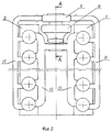
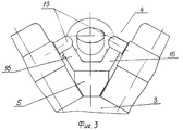
Изобретение поясняется чертежами, где на фиг. 1 изображен вид на двигатель со стороны трубокомпрессора, на фиг. 2 - вид на двигатель сверху, на фиг. 3 - вид на двигатель со стороны, противоположной турбокомпрессору, при этом все узлы и агрегаты, расположенные в развале блоков, условно не показаны, на фиг. 4 - разрез А-А на фиг. 2. The invention is illustrated by drawings, where in FIG. 1 shows a view of the engine from the side of the compressor, FIG. 2 is a top view of the engine, in FIG. 3 is a view of the engine from the side opposite to the turbocharger, while all the nodes and assemblies located in the collapse of the blocks are not shown conditionally, in FIG. 4 is a section AA in FIG. 2.
Устройство содержит блоки 1 и 2 цилиндров, установленные на картере 3 и образующие V-образный развал 4. Впускной ресивер 5 размещен в развале 4 блоков 1 и 2 и закреплен на картере 3. Впускной ресивер 5 снабжен входным 6 и выходным 7 (фиг. 4) окнами. Турбокомпрессор содержит газовую турбину 8, компрессор с улиткой 9 (фиг. 2) и узел 10 крепления компрессора к ресиверу 5. Выпускные коллекторы 11 размещены на внешних поверхностях блоков 1 и 2 и сообщены посредством газовых патрубков 12 с турбиной 8. Впускные коллекторы 13 расположены на внутренних поверхностях блоков 1 и 2 и сообщены через впускной ресивер 5 с улиткой 9 компрессора. Улитка 9 компрессора сообщена с входным окном 6 ресивера 5. Выходное окно 7 ресивера 5 обращено внутрь развала 4 блоков. Улитка 9 компрессора выполнена несимметричной и охватывает подшипниковый узел 14 турбокомпрессора. Турбокомпрессор закреплен на ресивере 5 болтами 15, проходящими через крепление 10, размещенное на улитке 9. Выходное окно 7 ресивера сообщено с впускными коллекторами 13 восходящими патрубками 16, продолженными вдоль внутренней поверхности блоков 1 и 2 цилиндров. The device contains
Выходное отверстие улитки 9 компрессора и сообщенное с ним входное окно 6 ресивера 5 выполнены прямоугольными, а боковые стенки 17 ресивера 5 эквидистантны внутренним поверхностям блоков 1 и 2. Наружная торцевая стенка 18 ресивера 5 плавно переходит в его днище 19, которое в свою очередь плавно сопряжено с внутренней торцевой стенкой 20. На входном фланце ресивера 5 выполнено дополнительное отверстие 21. Ответное отверстие 22 выполнено на фланце улитки 9 компрессора и соединено каналом, проложенным в стенке улитки 9 (на фиг. не показан), с масляной полостью турбокомпрессора. Стекающее масло по трубопроводу 23 отводится в картер 3 двигателя. В совмещенных отверстиях 21 и 22 установлена втулка 24 с радиальным уплотнением, служащая для центровки турбокомпрессора на ресивере 5. Вторым элементом для центровки служит штифт (а на фиг. не показан). The outlet opening of the compressor scroll 9 and the inlet window 6 of the
Для обеспечения надежности конструкции, а также надежности соединений воздушных и газовых трасс, газовые патрубки 12, соединяющие выпускные коллекторы 11 с турбиной 8, а также восходящие патрубки 15, соединяющие впускной ресивер 5 с впускными коллекторами 13, снабжены компенсаторами монтажных смещений и тепловых расширений. To ensure the reliability of the design, as well as the reliability of the connections of the air and gas routes, gas pipes 12 connecting the exhaust manifolds 11 to the
Для подачи впускного воздуха к компрессору служит впускной патрубок 25, размещенный в развале 4 блоков в пространстве между восходящими патрубками 15. To supply the intake air to the compressor, the
Двигатель работает следующим образом. Впускной воздух через патрубок 25 поступает к колесу компрессора, в котором сжимается и подается в улитку 9. Выполнение улитки 9 несимметричной позволяет повысить КПД компрессора. ([5] Б. Эккерт. Осевые и центробежные компрессоры. Машгиз. 1959, стр. 561 - 564). Из улитки 9 через входное окно 6 ресивера 5 воздух поступает к выходному окну 7. Благодаря указанному выше обеспечению максимальных сечений окон и самого ресивера обеспечиваются минимальные потери давления впускного воздуха. От выпускного окна 7 по имеющим минимальную длину восходящим патрубкам 15 воздух подается к впускным коллекторам 13, через которые распределяется по цилиндрам двигателя. The engine operates as follows. The inlet air through the
Отработавшие газы через выпускной коллектор 11 поступает в турбину 8. The exhaust gas through the
Монтажные смещения и допуски на изготовление деталей при сборке двигателя компенсируются компенсаторами, размещенными на выпускных 12 и восходящих 16 патрубках. Mounting offsets and tolerances for the manufacture of parts during engine assembly are compensated by compensators located on the exhaust 12 and ascending 16 nozzles.
Тепловые расширения газовых трасс воспринимаются компенсаторами тепловых расширений. Thermal expansion of gas paths is perceived by compensators of thermal expansion.
Турбокомпрессор, как единый узел, надежно закреплен на впускном ресивере 5, который, в свою очередь, закреплен на корпусной детали - картере 2. The turbocharger, as a single unit, is securely mounted on the
Этим обеспечена надежность двигателя при работе. Таким образом, заявляемое устройство характеризуется повышенными габаритно-массовыми показателями при высокой экономичности и достаточной надежности. This ensures the reliability of the engine during operation. Thus, the claimed device is characterized by increased overall mass indicators with high efficiency and sufficient reliability.
Все элементы заявляемого устройства и устройство в целом изготавливаются на предприятиях отечественной промышленности, при этом не применяются недоступные материалы и технологии. All elements of the claimed device and the device as a whole are manufactured at domestic enterprises, while inaccessible materials and technologies are not used.
В настоящее время на Челябинском тракторном заводе изготовлено несколько опытных образцов, проходящих доводочные испытания. Currently, at the Chelyabinsk Tractor Plant, several prototypes undergoing development tests have been manufactured.
Claims (2)
Priority Applications (1)
| Application Number | Priority Date | Filing Date | Title |
|---|---|---|---|
| RU99106776/06A RU2158373C1 (en) | 1999-04-12 | 1999-04-12 | Turbocharged v-type internal combustion engine |
Applications Claiming Priority (1)
| Application Number | Priority Date | Filing Date | Title |
|---|---|---|---|
| RU99106776/06A RU2158373C1 (en) | 1999-04-12 | 1999-04-12 | Turbocharged v-type internal combustion engine |
Publications (1)
| Publication Number | Publication Date |
|---|---|
| RU2158373C1 true RU2158373C1 (en) | 2000-10-27 |
Family
ID=20218005
Family Applications (1)
| Application Number | Title | Priority Date | Filing Date |
|---|---|---|---|
| RU99106776/06A RU2158373C1 (en) | 1999-04-12 | 1999-04-12 | Turbocharged v-type internal combustion engine |
Country Status (1)
| Country | Link |
|---|---|
| RU (1) | RU2158373C1 (en) |
Cited By (5)
| Publication number | Priority date | Publication date | Assignee | Title |
|---|---|---|---|---|
| WO2006099668A1 (en) * | 2005-03-24 | 2006-09-28 | Richwood Creek Pty Ltd | An apparatus for a vehicle |
| US20110277709A1 (en) * | 2010-05-17 | 2011-11-17 | Ford Global Technologies, Llc | Supercharged engine system |
| RU2505689C2 (en) * | 2008-06-03 | 2014-01-27 | Вяртсиля Финланд Ой | Piston engine |
| RU2573075C2 (en) * | 2011-04-21 | 2016-01-20 | Мак Тракс, Инк. | Power unit with turbine bypass and methods of its operation |
| RU2790110C2 (en) * | 2021-07-05 | 2023-02-14 | Общество с ограниченной ответственностью "Челябинский тракторный завод - УРАЛТРАК" | Twelve-cylinder v-shaped internal combustion engine with gas-turbine supercharging |
Citations (5)
| Publication number | Priority date | Publication date | Assignee | Title |
|---|---|---|---|---|
| US4372120A (en) * | 1979-10-26 | 1983-02-08 | General Motors Corporation | V-Type engine intake with vibration isolated manifold connector |
| SU1276842A1 (en) * | 1985-04-17 | 1986-12-15 | Ордена Ленина И Ордена Трудового Красного Знамени Завод Транспортного Машиностроения Им.В.И.Ленина | Device for supercharging internal combustion engine |
| US4643137A (en) * | 1984-04-09 | 1987-02-17 | Mazda Motor Corporation | Engine construction |
| SU1296735A1 (en) * | 1981-04-21 | 1987-03-15 | Завод транспортного машиностроения им.В.И.Ленина | Device for supercharging internal combustion engine |
| SU1710799A1 (en) * | 1989-12-29 | 1992-02-07 | Барнаульский завод транспортного машиностроения им.В.И.Ленина | Device for pressure charging of vee internal-combustion engine |
-
1999
- 1999-04-12 RU RU99106776/06A patent/RU2158373C1/en not_active IP Right Cessation
Patent Citations (5)
| Publication number | Priority date | Publication date | Assignee | Title |
|---|---|---|---|---|
| US4372120A (en) * | 1979-10-26 | 1983-02-08 | General Motors Corporation | V-Type engine intake with vibration isolated manifold connector |
| SU1296735A1 (en) * | 1981-04-21 | 1987-03-15 | Завод транспортного машиностроения им.В.И.Ленина | Device for supercharging internal combustion engine |
| US4643137A (en) * | 1984-04-09 | 1987-02-17 | Mazda Motor Corporation | Engine construction |
| SU1276842A1 (en) * | 1985-04-17 | 1986-12-15 | Ордена Ленина И Ордена Трудового Красного Знамени Завод Транспортного Машиностроения Им.В.И.Ленина | Device for supercharging internal combustion engine |
| SU1710799A1 (en) * | 1989-12-29 | 1992-02-07 | Барнаульский завод транспортного машиностроения им.В.И.Ленина | Device for pressure charging of vee internal-combustion engine |
Cited By (7)
| Publication number | Priority date | Publication date | Assignee | Title |
|---|---|---|---|---|
| WO2006099668A1 (en) * | 2005-03-24 | 2006-09-28 | Richwood Creek Pty Ltd | An apparatus for a vehicle |
| US7694667B2 (en) | 2005-03-24 | 2010-04-13 | Richwood Creek Pty Ltd. | Apparatus for a vehicle |
| RU2505689C2 (en) * | 2008-06-03 | 2014-01-27 | Вяртсиля Финланд Ой | Piston engine |
| US20110277709A1 (en) * | 2010-05-17 | 2011-11-17 | Ford Global Technologies, Llc | Supercharged engine system |
| US8464696B2 (en) * | 2010-05-17 | 2013-06-18 | Ford Global Technologies, Llc | Supercharged engine system |
| RU2573075C2 (en) * | 2011-04-21 | 2016-01-20 | Мак Тракс, Инк. | Power unit with turbine bypass and methods of its operation |
| RU2790110C2 (en) * | 2021-07-05 | 2023-02-14 | Общество с ограниченной ответственностью "Челябинский тракторный завод - УРАЛТРАК" | Twelve-cylinder v-shaped internal combustion engine with gas-turbine supercharging |
Similar Documents
| Publication | Publication Date | Title |
|---|---|---|
| RU2065526C1 (en) | Sucking plant for internal combustion engine | |
| KR100986061B1 (en) | Engine with integral exhaust manifold and cylinder head | |
| US8813728B2 (en) | Intake system for an internal combustion engine | |
| CN101469631B (en) | Exhaust gas collector | |
| US8206133B2 (en) | Turbocharger housing with integral inlet and outlet openings | |
| US8220264B2 (en) | Integrated inboard exhaust manifolds for V-type engines | |
| CN101113703B (en) | Intake manifold assembly | |
| US4693084A (en) | Charge cooler angle duct | |
| JP2002303145A (en) | Internal combustion engine with turbocharger | |
| JP3329220B2 (en) | Intake structure of supercharged engine | |
| CN114687853B (en) | Engine device | |
| US20040118389A1 (en) | Heat exchanger for a supercharger | |
| EP2792868B1 (en) | Exhaust turbine supercharger | |
| RU2158373C1 (en) | Turbocharged v-type internal combustion engine | |
| JP4265365B2 (en) | Internal combustion engine | |
| JP4265364B2 (en) | Internal combustion engine | |
| CN218454775U (en) | Engine and automobile | |
| CN1095523C (en) | Multi-cylinder four-stroke internal combustion engine | |
| CN112627969B (en) | A supercharging module for a V-type diesel engine | |
| SU1710799A1 (en) | Device for pressure charging of vee internal-combustion engine | |
| CN116529467B (en) | Exhaust manifold having turbine connector with turbine feet | |
| CN216588883U (en) | Gas engine intake manifold | |
| RU2083855C1 (en) | V-type supercharged internal combustion engine | |
| CN213016571U (en) | Engine cylinder cover assembly integrated with air inlet pipe | |
| SU1276842A1 (en) | Device for supercharging internal combustion engine |
Legal Events
| Date | Code | Title | Description |
|---|---|---|---|
| PC4A | Invention patent assignment |
Effective date: 20050620 |
|
| MM4A | The patent is invalid due to non-payment of fees |
Effective date: 20150413 |
|
| NF4A | Reinstatement of patent |
Effective date: 20160427 |
|
| MM4A | The patent is invalid due to non-payment of fees |
Effective date: 20170413 |