RU2157592C2 - Method for reception and search of packet- switched signal - Google Patents
Method for reception and search of packet- switched signal Download PDFInfo
- Publication number
- RU2157592C2 RU2157592C2 RU97120123/09A RU97120123A RU2157592C2 RU 2157592 C2 RU2157592 C2 RU 2157592C2 RU 97120123/09 A RU97120123/09 A RU 97120123/09A RU 97120123 A RU97120123 A RU 97120123A RU 2157592 C2 RU2157592 C2 RU 2157592C2
- Authority
- RU
- Russia
- Prior art keywords
- search
- signal
- shift
- samples
- walsh
- Prior art date
Links
Images


Classifications
-
- H—ELECTRICITY
- H04—ELECTRIC COMMUNICATION TECHNIQUE
- H04B—TRANSMISSION
- H04B1/00—Details of transmission systems, not covered by a single one of groups H04B3/00 - H04B13/00; Details of transmission systems not characterised by the medium used for transmission
- H04B1/69—Spread spectrum techniques
- H04B1/707—Spread spectrum techniques using direct sequence modulation
- H04B1/7073—Synchronisation aspects
- H04B1/7075—Synchronisation aspects with code phase acquisition
- H04B1/70751—Synchronisation aspects with code phase acquisition using partial detection
- H04B1/70752—Partial correlation
-
- H—ELECTRICITY
- H04—ELECTRIC COMMUNICATION TECHNIQUE
- H04B—TRANSMISSION
- H04B7/00—Radio transmission systems, i.e. using radiation field
- H04B7/24—Radio transmission systems, i.e. using radiation field for communication between two or more posts
- H04B7/26—Radio transmission systems, i.e. using radiation field for communication between two or more posts at least one of which is mobile
-
- H—ELECTRICITY
- H04—ELECTRIC COMMUNICATION TECHNIQUE
- H04B—TRANSMISSION
- H04B1/00—Details of transmission systems, not covered by a single one of groups H04B3/00 - H04B13/00; Details of transmission systems not characterised by the medium used for transmission
- H04B1/69—Spread spectrum techniques
- H04B1/707—Spread spectrum techniques using direct sequence modulation
- H04B1/7073—Synchronisation aspects
- H04B1/7075—Synchronisation aspects with code phase acquisition
- H04B1/70756—Jumping within the code, i.e. masking or slewing
-
- H—ELECTRICITY
- H04—ELECTRIC COMMUNICATION TECHNIQUE
- H04B—TRANSMISSION
- H04B7/00—Radio transmission systems, i.e. using radiation field
- H04B7/24—Radio transmission systems, i.e. using radiation field for communication between two or more posts
- H04B7/26—Radio transmission systems, i.e. using radiation field for communication between two or more posts at least one of which is mobile
- H04B7/2628—Radio transmission systems, i.e. using radiation field for communication between two or more posts at least one of which is mobile using code-division multiple access [CDMA] or spread spectrum multiple access [SSMA]
-
- H—ELECTRICITY
- H04—ELECTRIC COMMUNICATION TECHNIQUE
- H04J—MULTIPLEX COMMUNICATION
- H04J13/00—Code division multiplex systems
- H04J13/0007—Code type
- H04J13/004—Orthogonal
- H04J13/0048—Walsh
-
- H—ELECTRICITY
- H04—ELECTRIC COMMUNICATION TECHNIQUE
- H04B—TRANSMISSION
- H04B1/00—Details of transmission systems, not covered by a single one of groups H04B3/00 - H04B13/00; Details of transmission systems not characterised by the medium used for transmission
- H04B1/69—Spread spectrum techniques
- H04B1/707—Spread spectrum techniques using direct sequence modulation
- H04B1/7097—Interference-related aspects
- H04B1/711—Interference-related aspects the interference being multi-path interference
- H04B1/7113—Determination of path profile
-
- H—ELECTRICITY
- H04—ELECTRIC COMMUNICATION TECHNIQUE
- H04B—TRANSMISSION
- H04B1/00—Details of transmission systems, not covered by a single one of groups H04B3/00 - H04B13/00; Details of transmission systems not characterised by the medium used for transmission
- H04B1/69—Spread spectrum techniques
- H04B1/707—Spread spectrum techniques using direct sequence modulation
- H04B1/7097—Interference-related aspects
- H04B1/711—Interference-related aspects the interference being multi-path interference
- H04B1/7115—Constructive combining of multi-path signals, i.e. RAKE receivers
- H04B1/7117—Selection, re-selection, allocation or re-allocation of paths to fingers, e.g. timing offset control of allocated fingers
-
- H—ELECTRICITY
- H04—ELECTRIC COMMUNICATION TECHNIQUE
- H04B—TRANSMISSION
- H04B2201/00—Indexing scheme relating to details of transmission systems not covered by a single group of H04B3/00 - H04B13/00
- H04B2201/69—Orthogonal indexing scheme relating to spread spectrum techniques in general
- H04B2201/707—Orthogonal indexing scheme relating to spread spectrum techniques in general relating to direct sequence modulation
- H04B2201/70703—Orthogonal indexing scheme relating to spread spectrum techniques in general relating to direct sequence modulation using multiple or variable rates
Landscapes
- Engineering & Computer Science (AREA)
- Computer Networks & Wireless Communication (AREA)
- Signal Processing (AREA)
- Mobile Radio Communication Systems (AREA)
- Radio Relay Systems (AREA)
- Monitoring And Testing Of Transmission In General (AREA)
- Position Fixing By Use Of Radio Waves (AREA)
- Radio Transmission System (AREA)
Abstract
Description
Область техники
Настоящее изобретение относится к системам связи с расширенным спектром, более конкретно к обработке сигнала в сотовой телефонной системе связи.Technical field
The present invention relates to spread spectrum communication systems, and more particularly to signal processing in a cellular telephone communication system.
Описание известного уровня техники
В радиотелефонных системах связи, таких как сотовые телефонные системы, системы персональной связи, и локальные замкнутые системы радиосвязи, многие пользователи осуществляют связь по радиоканалу для подсоединения к проводным телефонным системам. Связь по радиоканалу может быть одним из множества методов множественного доступа, обеспечивающих возможность большому числу абонентов использовать ограниченный частотный спектр. Эти методы множественного доступа включают множественный доступ с временным разделением /МДВР/ каналов, множественный доступ с частотным разделением /МДЧР/ и множественный доступ с кодовым разделением /МДКР/. Метод МДКР имеет множество преимуществ, причем типовая система с МДКР раскрыта в Патенте США N 4901307, от 13 февраля 1990 на "Систему связи множественного доступа с расширенным спектром, использующую спутниковые или наземные ретрансляторы", переуступленном правопреемнику настоящего изобретения.Description of the prior art
In radiotelephone communication systems, such as cellular telephone systems, personal communication systems, and local closed-loop radio communication systems, many users communicate over the air to connect to wired telephone systems. Radio communication can be one of many multiple access methods that enable a large number of subscribers to use a limited frequency spectrum. These multiple access methods include time division multiple access / TDMA / channels, frequency division multiple access / FDMA / and code division multiple access / CDMA /. The CDMA method has many advantages, and a typical CDMA system is disclosed in U.S. Patent No. 4,901,307, February 13, 1990, on an "Enhanced Spectrum Multiple Access Communication System Using Satellite or Terrestrial Relays," assigned to the assignee of the present invention.
В упомянутом патенте раскрыт способ множественного доступа, в котором большое количество мобильных пользователей телефонной системы, каждый из которых имеет приемопередатчик, осуществляют связь через спутниковые ретрансляторы или наземные базовые станции с использованием сигналов связи в режиме МДКР с расширенным спектром. При осуществлении связи в режиме МДКР частотный спектр может использоваться многократно, что позволяет увеличить пропускную способность системы для пользователей. The aforementioned patent discloses a multiple access method in which a large number of mobile telephone system users, each of which has a transceiver, communicate via satellite repeaters or ground base stations using spread spectrum CDMA communication signals. When communicating in CDMA mode, the frequency spectrum can be used repeatedly, which can increase the system throughput for users.
Способы модуляции МДКР, раскрытые в Патенте США N 4901307, имеют множество преимуществ по сравнению со способами узкополосной модуляции, применяемыми в системах связи, использующих спутниковые и наземные каналы. В наземных каналах возникают специфические требования к системе связи, в частности, по отношению к многолучевым сигналам. Применение способов МДКР позволяет решить специфические проблемы, связанные с использованием наземного канала, путем преодоления отрицательного влияния многолучевого распространения, например, замирания, не теряя в то же время их преимуществ. CDMA modulation methods disclosed in US Pat. No. 4,901,307 have many advantages over narrowband modulation methods used in communication systems using satellite and terrestrial channels. In terrestrial channels, specific requirements arise for a communication system, in particular with respect to multipath signals. The application of CDMA methods allows solving specific problems associated with the use of a terrestrial channel by overcoming the negative effects of multipath propagation, for example, fading, without losing their advantages at the same time.
Способ МДКР, раскрытый в Патенте США N 4901307, предусматривает использование когерентной модуляции и демодуляции для обоих направлений линии связи при осуществлении связи между удаленным устройством радиосвязи и спутником. В нем соответственно раскрывается использование несущего пилот-сигнала в качестве когерентного фазового опорного сигнала для линии связи "спутник-удаленное устройство радиосвязи" и линии связи "базовая станция-удаленное устройство радиосвязи". Однако в наземном оборудовании сотовой связи наличие весьма сильного многолучевого затухания, приводящего к искажению фазы каналом, а также уровень мощности, необходимый для передачи несущего пилот-сигнала от удаленного устройства радиосвязи, затрудняет использование способа когерентной модуляции для линии связи "удаленное устройство радиосвязи-базовая станция". В Патенте США N 5103549 на "Систему и способ формирования сигналов в сотовой телефонной системе МДКР" от 25 июня 1990 года, переуступленном правопреемнику настоящего изобретения, предлагается средство для преодоления отрицательного влияния многолучевого распространения в канале связи "удаленное устройство радиосвязи-базовая станция" с использованием способов некогерентной модуляции и демодуляции. The CDMA method disclosed in US Pat. No. 4,901,307 provides for the use of coherent modulation and demodulation for both directions of a communication line when communicating between a remote radio communication device and a satellite. It accordingly discloses the use of a carrier pilot signal as a coherent phase reference signal for a satellite-remote radio communications device and a base station-remote radio communications communication line. However, in terrestrial cellular communication equipment, the presence of very strong multipath attenuation, which leads to phase distortion by the channel, as well as the power level necessary for transmitting the carrier pilot signal from a remote radio communication device, makes it difficult to use the coherent modulation method for the “remote radio communication device-base station” communication line " US Pat. No. 5,103,549 to "System and Method for Generating Signals in a CDMA Cellular Telephone System" of June 25, 1990, assigned to the assignee of the present invention, provides a means to overcome the negative effects of multipath propagation in a "remote radio communication base station" communication channel using methods of incoherent modulation and demodulation.
В сотовой телефонной системе с МДКР одна и та же полоса частот может быть использована для связи со всеми базовыми станциями. В приемнике базовой станции разделяемые сигналы многолучевого распространения, например, проступающие по трассе от абонентского пункта и по другой трассе после отражения от здания, могут быть объединены при обработке с разнесением для улучшения характеристик модема. Свойства сигналов МДКР, обеспечивающие выигрыш при обработке, также используются для различения сигналов, занимающих один и тот же частотный диапазон. Кроме того высокоскоростная псевдошумовая модуляция всегда обеспечивает возможность разделения различных трасс распространения одного и того же сигнала, при условии, если разница в задержках по трассам распространения превышает длительность элемента псевдошумового кода. Если в системе с МДКР используется частота следования элементов псевдошумового кода порядка 1 МГц, то выигрыш при обработке сигнала расширенного спектра, равный отношению расширенной полосы к частоте данных в системе, может быть получен для всех трасс распространения, имеющих задержки, отличающиеся более чем на одну микросекунду. Разница в задержках на трассе распространения в одну микросекунду соответствует разнице в расстояниях примерно 300 метров. Обычно городская среда обеспечивает разность задержек по трассам распространения сигналов, превышающую одну микросекунду. In a cellular telephone system with CDMA, the same frequency band can be used to communicate with all base stations. In a base station receiver, shared multipath signals, for example, appearing along a path from a subscriber station and along another path after reflection from a building, can be combined during diversity processing to improve modem performance. The properties of CDMA signals that provide processing gain are also used to distinguish between signals occupying the same frequency range. In addition, high-speed pseudo-noise modulation always provides the ability to separate different propagation paths of the same signal, provided that the difference in delays along the propagation paths exceeds the duration of the pseudo-noise code element. If a repetition rate of elements of a pseudo-noise code of the order of 1 MHz is used in a CDMA system, then the gain in processing the spread spectrum signal, equal to the ratio of the extended band to the data frequency in the system, can be obtained for all propagation paths having delays differing by more than one microsecond . The difference in delays on the propagation path of one microsecond corresponds to a difference in distances of approximately 300 meters. Typically, an urban environment provides a delay difference over signal paths that exceeds one microsecond.
Свойства наземного канала, связанные с многолучевым распространением, приводят к тому, что в приемник сигналы приходят по нескольким различным трассам распространения. Одной из характеристик канала с многолучевым распространением является разброс по времени, возникающий в сигнале, передаваемом через такой канал. Например, если по каналу с многолучевым распространением передается идеальный импульс, то принимаемый сигнал появляется в виде последовательности импульсов. Другой характерной особенностью канала с многолучевым распространением является то, что каждая трасса распространения сигнала может давать разный коэффициент затухания. Например, если по каналу с многолучевым распространением передается идеальный импульс, то каждый импульс принимаемой импульсной последовательности обычно имеет уровень, отличный от уровня других принимаемых импульсов. Еще одной характерной особенностью канала с многолучевым распространением является то, что каждая трасса распространения дает разную фазу сигнала. Например, если по каналу с многолучевым распространением передается идеальный импульс, то каждый импульс принимаемой последовательности обычно имеет фазу, отличающуюся от фазы других принимаемых импульсов. The properties of the terrestrial channel associated with multipath propagation result in signals arriving at the receiver along several different propagation paths. One of the characteristics of a multipath channel is the time spread that occurs in a signal transmitted through such a channel. For example, if a perfect pulse is transmitted over a multipath channel, the received signal appears as a train of pulses. Another characteristic feature of a multipath channel is that each signal path can produce a different attenuation coefficient. For example, if an ideal pulse is transmitted over a multipath channel, then each pulse of the received pulse sequence usually has a level different from the level of the other received pulses. Another characteristic feature of a channel with multipath propagation is that each propagation path gives a different phase of the signal. For example, if an ideal pulse is transmitted over a multipath channel, then each pulse of the received sequence usually has a phase different from the phase of the other received pulses.
При передаче по радиоканалу многолучевое распространение возникает благодаря отражению сигнала от препятствий, образуемых зданиями, деревьями, автомобилями и людьми. В общем случае радиоканал представляет собой нестационарный канал с многолучевым распространением из-за относительного перемещения объектов, создающих многолучевое распространение. Например, если по нестационарному каналу с многолучевым распространением передается идеальный импульс, то в принимаемой последовательности импульсов будет изменяться его положение во времени, затухание и фаза в функции времени передачи идеального импульса. When transmitted over a radio channel, multipath propagation occurs due to the reflection of a signal from obstacles formed by buildings, trees, cars and people. In the general case, a radio channel is an unsteady channel with multipath propagation due to the relative movement of objects that create multipath propagation. For example, if an ideal pulse is transmitted through an unsteady channel with multipath propagation, then in the received sequence of pulses its position in time, attenuation and phase as a function of the transmission time of the ideal pulse will change.
Многолучевое распространение может вызвать замирание сигнала в канале. Замирание является результатом характеристик фазирования канала с многолучевым распространением. Замирание появляется, когда векторы множества лучей суммируются неблагоприятным образом, образуя в результате принимаемый сигнал, меньший, чем любой отдельно взятый вектор. Например, если по каналу с многолучевым распространением передается гармонический сигнал, характеризуемый двумя трассами распространения, причем первая трасса имеет коэффициент ослабления X дБ, время задержки σ с фазовым сдвигом θ радиан, а вторая трасса имеет коэффициент ослабления X дБ, время задержки θ+π с фазовым сдвигом σ радиан, то на выходе канала принятый сигнал будет отсутствовать. Multipath propagation can cause signal fading in a channel. Fading is the result of the phasing characteristics of a multipath channel. Fading occurs when the vectors of multiple beams are summed in an unfavorable manner, resulting in a received signal smaller than any single vector. For example, if a harmonic signal characterized by two propagation paths is transmitted through a multipath channel, where the first path has an attenuation coefficient of X dB, the delay time σ with a phase shift θ is radian, and the second path has an attenuation coefficient of X dB, the delay time is θ + π s phase shift σ radian, then at the channel output the received signal will be absent.
В системах узкополосной модуляции, таких как аналоговая частотная модуляция, используемая в известных радиотелефонных системах, наличие многолучевого распространения в радиоканале приводит к существенному многолучевому замиранию. Однако, как было отмечено выше в случае широкополосной системы МДКР, в процессе демодуляции могут быть выделены разные трассы распространения. Такое разделение не только значительно уменьшает отрицательное воздействие замирания, но и дает преимущества, связанные с использованием системы МДКР. In narrow-band modulation systems, such as the analog frequency modulation used in known radiotelephone systems, the presence of multipath propagation in a radio channel leads to significant multipath fading. However, as noted above in the case of the CDMA broadband system, different propagation paths can be distinguished in the demodulation process. This separation not only significantly reduces the negative effects of fading, but also provides benefits associated with the use of the CDMA system.
Разнесение - один из способов уменьшения отрицательных влияний замирания. Следовательно, желательно обеспечить некоторую форму разнесения, что позволит уменьшить замирание в системе. Существуют три основных вида разнесения: временное разнесение, частотное разнесение и пространственное разнесение или разнесение по трассе распространения. Diversity is one way to reduce the negative effects of fading. Therefore, it is desirable to provide some form of diversity, which will reduce fading in the system. There are three main types of diversity: temporal diversity, frequency diversity, and spatial diversity or path diversity.
Временное разнесение обеспечивается с использованием повторения временного перемежения и кодирования с обнаружением и исправлением ошибок, которое вводит избыточность. В системе, использующей настоящее изобретение, можно применять любой из этих способов в качестве формы временного разнесения. Temporal diversity is provided using repetition of temporal interleaving and coding with error detection and correction, which introduces redundancy. In a system using the present invention, any of these methods may be used as a form of time diversity.
МДКР с присущей данному методу широкополосностью обеспечивает некоторую форму частотного разнесения путем распределения энергии сигнала в широкой полосе рабочих частот. Поэтому частотно-избирательное замирание проявляется только на небольшой части полосы рабочих частот сигнала МДКР. CDMA with the inherent broadness of this method provides some form of frequency diversity by distributing the signal energy in a wide band of operating frequencies. Therefore, frequency selective fading occurs only on a small part of the working band of the CDMA signal.
Пространственное разнесение и разнесение по трассе распространения обеспечивается посредством подачи сигнала с многолучевым распространением одновременно по нескольким линиям связи от удаленного устройства радиосвязи через две или более базовые станции и путем использования двух или более пространственно разнесенных антенных элементов на одной базовой станции. Кроме того разнесение по трассам распространения может быть получено путем использования среды многолучевого распространения посредством обработки расширенного спектра, что позволяет осуществлять прием и раздельную обработку сигнала, поступающего с различными задержками распространения, как было описано выше. Примеры разнесения по трассам распространения приведены в Патенте США N 5101501 на "Программируемое переключение связи в сотовой телефонной системе МДКР" от 21 марта 1992 года и Патенте США N 5109390 на "Приемник разнесенного приема в сотовой телефонной системе МДКР" от 8 октября 1991, переуступленных правопреемнику настоящего изобретения. Spatial diversity and diversity along the propagation path is provided by supplying a multipath signal simultaneously on several communication lines from a remote radio communication device through two or more base stations and by using two or more spatially separated antenna elements at one base station. In addition, spacing along propagation paths can be obtained by using a multipath propagation medium by spread spectrum processing, which allows reception and separate processing of a signal arriving with different propagation delays, as described above. Examples of spacing along propagation paths are given in US Pat. No. 5,101,501 to "Programmable Switching Communication in a CDMA Cellular Telephone System" dated March 21, 1992 and US Patent No. 5109390 to "Diversity Receiver in a CDMA Cellular Telephone System" dated October 8, 1991, assigned to the assignee of the present invention.
Отрицательное влияние замирания может быть до некоторой степени скомпенсировано в системе с МДКР посредством регулирования мощности передатчика. Система для управления мощностью базовой станции и удаленного модуля раскрыта в Патенте США N 5056109 на "Способ и устройство для управления передаваемой мощностью в сотовой мобильной телефонной системе МДКР" от 8 октября 1991 года, переуступленном правопреемнику настоящего изобретения. The negative effects of fading can be compensated to some extent in a CDMA system by controlling the power of the transmitter. A system for controlling the power of a base station and a remote module is disclosed in US Pat. No. 5,056,109 to "Method and apparatus for controlling transmitted power in a CDMA mobile telephone system" of October 8, 1991, assigned to the assignee of the present invention.
Способ МДКР, раскрытый в Патенте США N 4901307, предусматривает использование относительно длинных псевдоожиженных последовательностей /ПШП/, причем пользователю каждого удаленного устройства радиосвязи выделяется своя, отличная от других ПШП. Взаимная корреляция между различными ПШП и автокорреляция ПШП для всех временных сдвигов, отличных от нуля, имеют среднее значение, близкое к нулю, что позволяет различать сигналы различных пользователей при приеме. (Для получения нулевого среднего значения для автокорреляции и взаимной корреляции, требуется, чтобы логический "0" принял значение "1", а логическая "1" приняла значение "-1" или на исходное отображение логических уровней). The CDMA method disclosed in US Patent No. 4,901,307 provides for the use of relatively long fluidized sequences (FWPs), and a user different from other FWPs is allocated to a user of each remote radio communication device. The cross-correlation between different FWPs and autocorrelation of FWPs for all time shifts other than zero have an average value close to zero, which makes it possible to distinguish the signals of different users upon reception. (To obtain a zero average value for autocorrelation and cross-correlation, it is necessary that the logical "0" takes the value "1" and the logical "1" takes the value "-1" or to the initial display of the logical levels).
Однако такие псевдошумовые сигналы не ортогональны. Хотя взаимная корреляция по существу имеет нулевое среднее значение на всей длине последовательности, однако в течение короткого временного интервала, такого как время информационного бита, взаимная корреляция является случайной переменной с биномиальным распределением. При этом сигналы взаимодействуют друг с другом в основном таким же образом, как если бы они представляли собой широкополосный шум с гауссовым распределением с той же самой спектральной плотностью мощности. Таким образом, сигналы других пользователей или шум от взаимных помех в конечном счете ограничивают достигаемую пропускную способность. However, such pseudo noise signals are not orthogonal. Although cross-correlation essentially has a zero mean value over the entire length of the sequence, however, over a short time interval, such as information bit time, cross-correlation is a random variable with a binomial distribution. In this case, the signals interact with each other basically in the same way as if they were a wideband noise with a Gaussian distribution with the same power spectral density. Thus, other users' signals or noise from mutual interference ultimately limit the achievable throughput.
Специалистам хорошо известно, что можно сформировать набор из n ортогональных двоичных последовательностей, каждая длиной n, для n, являющегося любой степенью 2 (см. Digital Communications with Space Applications, S.W. Golomb et el. , Prentice-Hall, Inc., p.45-64). В принципе также известны наборы ортогональных бинарных последовательностей для большинства длин, которые кратны четырем и меньше двухсот. Один класс таких последовательностей, которые легко генерировать, называется функцией Уолша, известной так же, как матрица Адамара. It is well known to those skilled in the art that it is possible to form a set of n orthogonal binary sequences, each of length n, for n, which is any power of 2 (see Digital Communications with Space Applications, SW Golomb et el., Prentice-Hall, Inc., p. 45 -64). In principle, sets of orthogonal binary sequences for most lengths that are multiples of four and less than two hundred are also known. One class of sequences that are easy to generate is called the Walsh function, also known as the Hadamard matrix.
Функция Уолша n-го порядка может быть определена рекурcивно следующим образом:
![]()
где W' обозначает логическое дополнение W, a W(1)= |0|.The nth-order Walsh function can be defined recursively as follows:
![]()
where W 'denotes the logical complement W, and W (1) = | 0 |.
Таким образом,

Одной из строк матрицы функции Уолша является символ, последовательность или код Уолша. Матрица функции Уолша n-го порядка содержит n последовательностей, каждая из которых имеет длину n элементов Уолша. Каждый код Уолша имеет соответствующий индекс Уолша, где индекс Уолша относится к числу /от 1 до n/, соответствующему строке, в которой находится код Уолша. Например, для приведенной выше матрицы функции Уолша с n=8 все нулевые строки соответствуют индексу Уолша 1, а код Уолша 0,0,0,0,1,1,1,1, соответствует индексу Уолша 5.Thus,
One of the rows of the Walsh function matrix is a Walsh symbol, sequence, or code. The n-th order Walsh function matrix contains n sequences, each of which has a length of n Walsh elements. Each Walsh code has a corresponding Walsh index, where the Walsh index refers to the number / from 1 to n /, corresponding to the line in which the Walsh code is located. For example, for the above matrix of the Walsh function with n = 8, all zero rows correspond to the
Матрица функции Уолша n-го порядка (а также все другие ортогональные функции длиной n) обладают свойством, состоящим в том, что на интервале n бит взаимная корреляция между всеми несхожими последовательностями внутри набора равна нулю. Это вытекает из того, что каждая последовательность отличается от любой другой последовательности ровно половиной своих бит. Следует также отметить, что всегда существует одна последовательность, содержащая все нули, и что все другие последовательности содержат половину единиц и половину нулей. Символ Уолша, который состоит из всех логических нулей вместо половины из нулей и половины из единиц, называется нулевым символом Уолша. The matrix of the nth-order Walsh function (as well as all other orthogonal functions of length n) have the property that, on an interval of n bits, the cross-correlation between all dissimilar sequences within the set is zero. This follows from the fact that each sequence differs from any other sequence by exactly half its bits. It should also be noted that there is always one sequence containing all zeros, and that all other sequences contain half ones and half zeros. The Walsh symbol, which consists of all logical zeros instead of half of zeros and half of ones, is called the Walsh symbol of zero.
В канале обратной линии связи от удаленного устройства радиосвязи к базовой станции отсутствует пилот-сигнал, обеспечивающий привязку по фазе. Таким образом, имеется необходимость в способе, обеспечивающем высококачественную связь по каналу с замиранием, имеющему низкое отношение Eb/No/ отношение энергии на один бит к плотности мощности шума/. Модуляция функции Уолша в обратной линии связи является простым способом получения 64-ричной модуляции с когерентностью для набора из шести кодовых символов, отображенных в 64 кода Уолша. Характеристики наземного канала таковы, что частота изменения фазы относительно низка. Следовательно, путем выбора длины кода Уолша, короткого по сравнению с частотой изменения фазы в канале, возможна когерентная демодуляция на длине одного кода Уолша. In the reverse link channel from the remote radio communication device to the base station, there is no pilot signal providing phase locking. Thus, there is a need for a method providing high-quality fading channel communication having a low Eb / No ratio / one bit energy to noise power density / ratio. Modulation of the Walsh function in the reverse link is a simple way to obtain 64-decimal modulation with coherence for a set of six code symbols mapped to 64 Walsh codes. The characteristics of the terrestrial channel are such that the frequency of the phase change is relatively low. Therefore, by choosing the length of the Walsh code that is short compared to the frequency of the phase change in the channel, coherent demodulation over the length of one Walsh code is possible.
В канале обратной линии связи код Уолша определяется информацией, передаваемой из удаленного устройства радиосвязи. Например, трехбитовый информационный символ может быть отображен в приведенные выше восемь последовательностей W(8). "Обратное отображение" закодированных символов Уолша в оценку исходных информационных символов может быть выполнено в приемнике с помощью быстрого преобразования Адамара /БПА/ Предпочтительное "обратное отображение", или процесс селекции, дает "мягкое" /программируемое/решение, которое может быть передано в декодер для декодирования по критерию максимального правдоподобия. On the reverse link channel, the Walsh code is determined by the information transmitted from the remote radio communications device. For example, a three-bit information symbol may be mapped to the eight above sequences of W (8). A “reverse mapping” of the encoded Walsh symbols to an estimate of the original information symbols can be performed at the receiver using the fast Hadamard / BPA / Preferred “reverse mapping,” or selection process, provides a “soft” / programmable / solution that can be transmitted to the decoder for decoding by maximum likelihood criterion.
Процедура БПА используется для выполнения процесса "обратного отображения". Процедура БПА коррелирует принятую последовательность с каждой из возможных последовательностей Уолша. Для выбора наиболее вероятного значения корреляции, которое масштабируется и принимается в качестве "мягкого" решения, используется схема селекции. The BPA procedure is used to perform the “reverse mapping” process. The BPA procedure correlates the received sequence with each of the possible Walsh sequences. To select the most probable value of the correlation, which is scaled and accepted as a “soft” solution, a selection scheme is used.
Приемник сигнала с расширенным спектром с разнесенным приемом или многоканальный приемник /"Rake" - приемник/ содержит множество приемников данных для смягчения эффекта замирания. Обычно каждый приемник данных предназначается для демодулирования сигнала, пришедшего по своей, отличной от других трассе распространения, либо с использованием многоэлементных антенн, либо с использованием свойств многолучевого распространения канала. При демодуляции сигналов, модулированных в соответствии со схемой передачи ортогональных сигналов, каждый приемник данных коррелирует принимаемый сигнал с каждым из возможных значений отображения, используя процедуру БПА, БПА каждого приемника данных объединяются, и затем схема селекции выбирает наиболее вероятное значение корреляции, основываясь на максимальном объединенном выходном сигнале БПА для получения демодулированного символа "мягкого" решения. A receiver with a spread spectrum signal with diversity reception or a multi-channel receiver / "Rake" - receiver / contains many data receivers to mitigate the fading effect. Typically, each data receiver is designed to demodulate a signal that arrives on its own propagation path different from the others, either using multi-element antennas or using the properties of multipath channel propagation. When demodulating signals modulated in accordance with an orthogonal signal transmission scheme, each data receiver correlates the received signal with each of the possible display values using the BPA procedure, the BPA of each data receiver is combined, and then the selection scheme selects the most probable correlation value based on the maximum combined BPA output to obtain a demodulated soft decision symbol.
В системе, описанной в Патенте США N 5103459, сигнал вызова начинается в виде источника информации 9600 бит в секунду, который затем преобразуется кодером прямого исправления ошибок со скоростью 1/3 в выходной поток 28800 символов в секунду. Эти символы группируются по 6 для образования 4800 символов Уолша в секунду, причем каждый символ Уолша отбирает одну из шестидесяти четырех ортогональных функций Уолша длительностью по шестьдесят четыре элемента Уолша. Элементы Уолша модулируются с помощью генератора псевдошумовой последовательности, специфической для каждого пользователя. Затем данные, модулированные выделенной для каждого пользователя специфической псевдошумовой последовательностью, расщепляются на два сигнала, один из которых модулируется с помощью ПСП синфазного (I) канала, а другой модулируется с помощью ПСП квадратурного (Q) канала. Как I-канальная, так и Q-канальная модуляция дает четыре псевдошумовых элемента на один элемент Уолша с частотой псевдослучайного кода расширения спектра 1.2288 МГц. I- и Q-модулированные данные представляют собой квадратурную фазовую модуляцию со сдвигом, объединенную для передачи. In the system described in US Pat. No. 5,103,459, the call signal begins as an information source of 9,600 bits per second, which is then converted by the forward error correction encoder at 1/3 rate to an output stream of 28,800 characters per second. These symbols are grouped by 6 to form 4800 Walsh symbols per second, with each Walsh symbol selecting one of sixty-four Walsh orthogonal functions with a duration of sixty-four Walsh elements. Walsh elements are modulated using a pseudo noise sequence generator specific to each user. Then, the data modulated by the specific pseudo-noise sequence allocated for each user is split into two signals, one of which is modulated using the PSP in-phase (I) channel, and the other is modulated using the PSP quadrature (Q) channel. Both I-channel and Q-channel modulation produce four pseudo-noise elements per Walsh element with a frequency of a pseudo-random spreading code of 1.2288 MHz. I- and Q-modulated data is a quadrature phase shift modulation combined for transmission.
В сотовой системе МДКР, описанной в вышеупомянутом Патенте США N 4901307, каждая базовая станция обеспечивает в ограниченной территориальной зоне и связывает удаленные устройства радиосвязи в зоне обслуживания с помощью коммутатора сотовой системы с коммутируемой телефонной сетью общего пользования. Когда удаленное устройство радиосвязи приближается к зоне обслуживания другой базовой станции, маршрутизация вызова этого пользователя передается новой базовой станции. Канал передачи сигнала от базовой станции к удаленному устройству радиосвязи называется прямой линией связи, а канал передачи сигнала от удаленного устройства радиосвязи на базовую станцию называется обратной линией связи. In the CDMA cellular system described in the aforementioned US Patent No. 4,901,307, each base station provides in a limited territorial area and connects remote radio communication devices in the service area using a cellular system switch with a public switched telephone network. When the remote radio device approaches the service area of another base station, this user's call routing is transferred to the new base station. A channel for transmitting a signal from a base station to a remote radio communication device is called a forward link, and a channel for transmitting a signal from a remote radio device to a base station is called a reverse link.
Как было описано выше, интервал элемента псевдошумового кода определяет минимальное разнесение, которое должны иметь две трассы распространения, чтобы их можно было объединить. Прежде чем демодулировать разные трассы распространения сигналов, необходимо сначала определить относительные времена прихода /или сдвиги/ сигналов для разных трасс распространения в принимаемом сигнале. Модем канального элемента выполняет эту функцию посредством "поиска" в последовательности возможных сдвигов для трасс распространения и изменения энергии, принимаемой при каждом таком возможном сдвиге. Если энергия, связанная с возможным сдвигом, превышает некоторый порог, то такому сдвигу может быть присвоен элемент демодуляции сигнала. Затем сигнал, соответствующий этому сдвигу для трасс расширения, может быть просуммирован с составляющими от других элементов демодуляции для соответствующих сдвигов. Способ и устройство определения элементов демодуляции на основе оценки уровней энергии элементов демодуляции поисковой системы раскрыты в заявке на Патент США N 08/144902 от 28 октября 1993 года, переуступленной правопреемнику настоящего изобретения. Такой приемник с разнесением, или многоканальный /RAKE/ приемник, обеспечивает надежную цифровую связь, поскольку замирание должно иметь место для всех трасс одновременно, чтобы параметры суммарного сигнала ухудшились. As described above, the interval of the pseudo-noise code element determines the minimum diversity that two propagation paths must have in order to be combined. Before demodulating different signal propagation paths, you must first determine the relative arrival times / or shifts / signals for different propagation paths in the received signal. The channel element modem performs this function by “searching” in a sequence of possible shifts for propagation paths and changes in energy received at each such possible shift. If the energy associated with a possible shift exceeds a certain threshold, then a signal demodulation element can be assigned to such a shift. Then, the signal corresponding to this shift for the extension paths can be summed with components from other demodulation elements for the corresponding shifts. A method and apparatus for determining demodulation elements based on an assessment of energy levels of search engine demodulation elements are disclosed in US Patent Application No. 08/144902 of October 28, 1993, assigned to the assignee of the present invention. Such a diversity receiver, or multi-channel / RAKE / receiver, provides reliable digital communications, since fading must occur for all paths simultaneously, so that the parameters of the total signal deteriorate.
На фиг. 1 в качестве примера показан набор сигналов, поступающих на базовую станцию от одного удаленного устройства радиосвязи. Вертикальная ось представляет мощность в децибелах (дБ). На горизонтальной оси указана задержка времени прихода сигнала вследствие задержек многолучевого распространения. Ось, перпендикулярная плоскости страницы (не показана), представляет сегмент времени. Каждый пик сигнала в плоскости страницы соответствует одному и тому же моменту времени, хотя передача осуществлялась удаленным устройством радиосвязи в разные моменты времени. На общей плоскости пики, лежащие правее, соответствуют сигналу, переданному удаленным устройством радиосвязи раньше, чем сигналы, соответствующие пикам, лежащим левее. Например, самый левый пик 2 соответствует самому последнему переданному сигналу. Каждый пик сигнала 2-7 соответствует прохождению по разной трассе и, следовательно, имеет разное время задержки и разную амплитудную характеристику. Шесть различных сигнальных пиков, показанных в виде пиков 2-7, характеризуют собой среду с существенным многолучевым распространением. Обычная городская среда дает меньше пригодных для использования трасс распространения. Уровень собственных шумов системы представлен пиками и провалами, имеющими более низкие уровни энергии. Задачей поискового элемента является определение задержки, измеряемой по горизонтальной оси сигнальных пиков 2-7 для распределения потенциальных элементов демодуляции. Задачей элемента демодуляции является демодуляция набора пиков многолучевого распространения для суммирования их в единый выходной сигнал. Также задачей элементов демодуляции, распределенных по пикам многолучевого распространения, является слежение за пиком, так как он может сдвигаться во времени. In FIG. 1 as an example, a set of signals arriving at a base station from a single remote radio communication device is shown. The vertical axis represents the power in decibels (dB). The horizontal axis indicates the time delay of the signal due to the multipath delays. An axis perpendicular to the page plane (not shown) represents a time segment. Each peak of the signal in the page plane corresponds to the same moment in time, although the transmission was carried out by a remote radio communication device at different times. On the common plane, the peaks to the right correspond to the signal transmitted by the remote radio communication device earlier than the signals corresponding to the peaks to the left. For example, the
Также можно считать, что по горизонтальной оси отложены единицы сдвига элементов псевдошумового сигнала. В любой данный момент базовая станция принимает множество разных сигналов от одного удаленного устройства радиосвязи, каждый из которых распространялся по своей трассе и может иметь отличную от других задержку. Сигнал от удаленного устройства радиосвязи модулируется с помощью ПСП. Также на базовой станции генерируется копия ПСП. Каждый сигнал многолучевого распространения демодулируется на базовой станции отдельно с помощью кода ПСП, синхронизированного индивидуально. Можно считать, что координаты горизонтальной оси соответствуют сдвигу кода ПСП, который будет использован для демодуляции сигнала с этой координатой. It can also be considered that the units of the shift of the elements of the pseudo-noise signal are plotted on the horizontal axis. At any given moment, the base station receives many different signals from one remote radio communication device, each of which propagated along its own path and may have a delay different from the others. The signal from the remote radio communication device is modulated using the SRP. A copy of the SRP is also generated at the base station. Each multipath signal is demodulated at the base station separately using the SRP code, individually synchronized. We can assume that the coordinates of the horizontal axis correspond to the shift of the SRP code, which will be used to demodulate the signal with this coordinate.
Заметим, что каждый пик многолучевого распространения изменяется по амплитуде в функции времени, как это показано в виде неровного гребня каждого пика многолучевого распространения. На показанном ограниченном временном отрезке нет больших изменений в пиках многолучевого распространения. В более широком временном диапазоне пики многолучевого распространения исчезают и со временем создаются новые траектории. Пики также могут смещаться в сторону более ранних или более поздних сдвигов в результате изменения длины траектории при движении удаленного устройства радиосвязи в зоне действия базовой станции. Каждый элемент демодуляции отслеживает наибольшие изменения выделенного ему сигнала. Задачей процесса поиска является формирование описания текущей среды многолучевого распространения, воспринимаемой базовой станцией. Note that each peak of multipath propagation varies in amplitude as a function of time, as shown in the form of an uneven crest of each peak of multipath propagation. In the limited time period shown, there are no large changes in the multipath peaks. In a wider time range, the multipath peaks disappear and new trajectories are created over time. Peaks can also shift towards earlier or later shifts as a result of a change in the trajectory when a remote radio communication device moves in the coverage area of the base station. Each demodulation element tracks the largest changes in the signal allocated to it. The task of the search process is to generate a description of the current multipath propagation environment, perceived by the base station.
В обычной радиотелефонной системе связи в передатчике удаленного устройства радиосвязи может быть использована система вокодирования, которая кодирует речевую информацию в формате переменной скорости. Например, скорость передачи данных может снижаться из-за пауз в речи. Пониженная скорость передачи данных уменьшает уровень перекрестных помех для других пользователей, вызываемых передачей от удаленных устройств радиосвязи. В приемнике или в каком-то ином устройстве, связанным с приемником, используется система вокодирования для восстановления речевой информации. Вдобавок к речевой информации удаленным модулем может передаваться либо только неречевая информация, либо их сочетание. In a conventional radiotelephone communication system, a transmitter of a remote radio communication device may use a vocoding system that encodes speech information in a variable speed format. For example, data transfer rates may be reduced due to pauses in speech. A reduced data rate reduces the level of crosstalk for other users caused by transmission from remote radio devices. In the receiver or in some other device associated with the receiver, a vocoding system is used to restore voice information. In addition to voice information, the remote module can transmit either only non-speech information, or a combination of both.
Вокодер, подходящий для использования в такой среде, описывается в совместно поданной заявке на Патент США N 08/363170 на "Вокодер переменной скорости" от 23 декабря 1994 года, переуступленной правопреемнику настоящего изобретения. Этот вокодер из цифровых выборок речевой информации создает кодированные данные с четырьмя различными скоростями, например, примерно 8000 бит/с, 4000 бит/с, 2000 бит/с и 1000 бит/с на основе речевой активности в течение цикла длиной 20 мс. Каждый блок данных вокодера форматируется с использованием вспомогательных битов в виде кадров данных со скоростями 9600 бит/с, 4800 бит/с, 2400 бит/с и 1200 бит/с. Кадр данных максимальной скорости 9600 бит/с называется кадром полной скорости; кадр данных со скоростью 4800 бит/с называется кадром половинной скорости; кадр данных со скоростью 2400 бит/с называется кадром одной четвертой скорости и кадр данных со скоростью 1200 бит/с называется кадром одной восьмой скорости. Ни в процессе кодирования, ни в процессе форматирования кадров информация о скорости не включается в данные. Если удаленное устройство радиосвязи передает данные со скоростью, меньшей, чем полная скорость, то рабочий цикл сигнала, передаваемого удаленными устройствами радиосвязи, будет такой же, как скорость передачи данных. Например, сигнал с одной четвертой скорости от удаленного устройства радиосвязи передается только одну четвертую часть времени. A vocoder suitable for use in such an environment is described in a co-filed application for US Patent No. 08/363170 for a Variable Speed Vocoder of December 23, 1994, assigned to the assignee of the present invention. This vocoder from digital samples of speech information creates encoded data at four different rates, for example, approximately 8000 bps, 4000 bps, 2000 bps and 1000 bps based on speech activity over a 20 ms cycle. Each vocoder data block is formatted using auxiliary bits in the form of data frames with speeds of 9600 bps, 4800 bps, 2400 bps and 1200 bps. A data frame with a maximum speed of 9600 bps is called a full speed frame; a data frame at 4800 bps is called a half rate frame; a data frame with a speed of 2400 bps is called a frame of one fourth speed and a data frame with a speed of 1200 bps is called a frame of one eighth speed. Neither in the encoding process, nor in the process of formatting frames, speed information is included in the data. If the remote radio communication device transmits data at a speed lower than the full speed, then the duty cycle of the signal transmitted by the remote radio communication devices will be the same as the data rate. For example, a signal at one-fourth of the speed from a remote radio communication device is transmitted only one-fourth of the time.
Удаленное устройство радиосвязи включает в себя рандомизатор пакетов данных. Рандомизатор пакетов данных определяет, в течение каких интервалов времени удаленное устройство радиосвязи ведет передачу и в течение каких интервалов времени он не ведет передачу при условии заданной скорости передачи данных, конкретный индентификационный номер удаленного устройства радиосвязи и время суток. При работе со скоростью, меньшей полной скорости, рандомизатор пакетов данных в составе удаленного устройства радиосвязи распределяет псевдослучайным образом интервалы активного времени внутри пакета передачи. Соответствующий рандомизатор пакетов данных включается также и в состав базовой станции, так что базовая станция может воссоздать псевдослучайное распределение на основе времени суток и конкретного идентификационного номера удаленного устройства радиосвязи, но базовая станция не знает априори скорость передачи данных передаваемого сигнала. The remote radio communication device includes a data packet randomizer. The data packet randomizer determines during which time intervals the remote radio communication device transmits and during which time intervals it does not transmit, provided the data rate is set, the specific identification number of the remote radio communication device and time of day. When operating at a speed less than full speed, the data packet randomizer as part of a remote radio communication device pseudo-randomly allocates active time intervals within a transmission packet. The corresponding randomizer of data packets is also included in the base station, so that the base station can recreate a pseudo-random distribution based on the time of day and the specific identification number of the remote radio communication device, but the base station does not know a priori the data rate of the transmitted signal.
Интервалы времени при одной восьмой скорости определяют так называемую "учитываемую" группу временных интервалов. Удаленное устройство радиосвязи, работающее с одной четвертой скорости, ведет передачу в течение временных интервалов "учитываемой" группы и еще одного набора распределенных псевдослучайным образом выбранных интервалов. Удаленное устройство радиосвязи, работающее с половинной скоростью, ведет передачу во время временных интервалов одной четвертой скорости и другого набора распределенных псевдослучайным образом интервалов. Удаленное устройство радиосвязи, работающее с полной скоростью, ведет передачу непрерывно. Таким путем, независимо от скорости передачи данных передаваемого сигнала, каждый временной интервал, соответствующий "учитываемой" группе, однозначно определяет интервал времени, когда соответствующее удаленное устройство радиосвязи передает сигнал. Дополнительные подробности, касающиеся рандомизатора пакета данных, описываются в совместно поданной заявке на Патент США N 08/291647 на "Рандомизатор пакетов данных" от 16 августа 1994 года, переуступленной правопреемнику настоящего изобретения. The time intervals at one eighth of the speed determine the so-called "considered" group of time intervals. A remote radiocommunication device operating at one fourth speed transmits during the time intervals the “counted” group and another set of pseudo-randomly distributed selected intervals. The remote half-speed radio communication device transmits during the time intervals one fourth speed and another set of pseudo-randomly distributed intervals. A remote radio device operating at full speed transmits continuously. In this way, regardless of the data rate of the transmitted signal, each time interval corresponding to the "accounted" group uniquely determines the time interval when the corresponding remote radio communication device transmits a signal. Further details regarding the randomizer of the data packet are described in the co-filed application for US Patent No. 08/291647 for the “Randomizer of Data Packets” of August 16, 1994, assigned to the assignee of the present invention.
Чтобы сэкономить системные ресурсы для активных данных при передаче речи, удаленное устройство радиосвязи не передает информацию о скорости передачи данных для каждого блока данных. Следовательно, приемник должен определить скорость, при которой данные кодировались и передавались на основе передаваемого сигнала, так чтобы вокодер, связанный с приемником, мог правильно восстановить речевую информацию. Способ определения скорости, при которой кодировались пакетные данные, без получения информации о скорости от приемника, раскрываются в совместно поданной заявке на патент США N 08/233570 на "Способ и устройство для определения скорости передачи данных с переменной скоростью в приемнике системы связи" от 26 апреля 1994 года, переуступленной правопреемнику настоящего изобретения. Способ определения скорости данных, раскрытый в вышеупомянутой заявке, реализуется после того, как был принят и демодулирован сигнал, вследствие чего информация о скорости процесса поиска отсутствует. In order to save system resources for active data during voice transmission, the remote radio communication device does not transmit data rate information for each data block. Therefore, the receiver must determine the rate at which data is encoded and transmitted based on the transmitted signal, so that the vocoder associated with the receiver can correctly restore voice information. A method for determining the rate at which packet data was encoded without receiving speed information from a receiver is disclosed in co-filed US Patent Application No. 08/233570 on “Method and Apparatus for Determining Variable Speed Data Rate in a Communication System Receiver” from 26 April 1994, assigned to the assignee of the present invention. The method for determining the data rate disclosed in the aforementioned application is implemented after a signal has been received and demodulated, as a result of which there is no information about the speed of the search process.
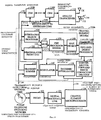
На базовой станции из ансамбля принимаемых сигналов вызовов должен быть идентифицирован каждый отдельный сигнал удаленного устройства радиосвязи. Система и способ демодуляции сигнала удаленного устройства радиосвязи, принимаемого на базовой станции, описаны, например, в Патенте США N 5103459. На фиг. 2 показана блок-схема оборудования базовой станции, описанного в Патенте США N 5103459, для демодуляции сигнала удаленного устройства радиосвязи, передаваемого по обратной линии связи. At the base station, each individual signal of the remote radio communication device must be identified from the ensemble of received call signals. A system and method for demodulating a signal of a remote radio communication device received at a base station are described, for example, in US Pat. No. 5,103459. FIG. 2 is a block diagram of base station equipment described in US Pat. No. 5,103,459 for demodulating a signal of a remote radio communication device transmitted over a reverse link.
Известная типовая базовая станция содержит многоэлементное независимое поисковое устройство и элементы демодуляции. Поисковое устройство и элементы демодуляции управляются микропроцессором. В рассматриваемом в качестве примера варианте для поддержания высокой пропускной способности системы ни одно удаленное устройство радиосвязи в системе не передает пилот-сигнал. Отсутствие пилот-сигнала в обратной линии связи увеличивает время, необходимое для анализа всех возможных временных сдвигов, с которыми может быть принят сигнал от удаленного устройства радиосвязи. Обычно пилот-сигнал передается с уровнем мощности, более высоким, чем сигналы трафика, что повышает отношение сигнал-шум принимаемого пилот-сигнала по сравнению с принимаемыми канальными сигналами трафика. В противоположность этому в идеале каждое удаленное устройство радиосвязи передает сигнал обратной линии связи, который поступает с уровнем мощности, равным уровню мощности, принимаемому от любого другого удаленного устройства радиосвязи, и следовательно, имеющий низкое отношение сигнал-шум. Кроме того, канал пилот-сигнала передает известную последовательность данных. Без пилот-сигнала в процессе поиска необходимо проверять все варианты, по которым могли быть переданы данные. Known typical base station contains a multi-element independent search device and demodulation elements. The search device and demodulation elements are controlled by a microprocessor. In the exemplary embodiment, to maintain a high system capacity, no remote radio device in the system transmits a pilot signal. The absence of a pilot signal in the reverse link increases the time required to analyze all possible time shifts with which a signal from a remote radio communication device can be received. Typically, the pilot signal is transmitted with a power level higher than the traffic signals, which increases the signal-to-noise ratio of the received pilot signal compared to the received channel traffic signals. In contrast, ideally, each remote radio communication device transmits a reverse link signal that arrives at a power level equal to the power received from any other remote radio communication device, and therefore having a low signal to noise ratio. In addition, the pilot channel transmits a known data sequence. Without a pilot signal in the search process, it is necessary to check all the options by which data could be transmitted.
На фиг. 2 в качестве примера показан вариант известной базовой станции. Базовая станция на фиг.2 имеет одну или более антенн 12, принимающих сигналы обратных линий связи удаленных устройств радиосвязи 14. Обычно зона действия городской базовой станции разделена на три субзоны, называемые секторами. При двух антеннах на один сектор обычная базовая станция имеет всего шесть приемных антенн. Принимаемые сигналы преобразуются с понижением частоты до полосы частот модулирующих сигналов аналоговым приемником 16, который разбивает сигнал на I и Q каналы и посылает эти цифровые значения по сигнальным шинам 18 в модем канального элемента 20. Обычная базовая станция содержит множество модемов канальных элементов, таких как модем канального элемента 20 /на фиг. 2 не показаны/. Каждый модем канального элемента 20 поддерживает одного пользователя. В предпочтительном варианте модем канального элемента 20 содержит четыре элемента демодуляции 22 и восемь поисковых устройств 26. Микропроцессор 34 управляет работой элементов демодуляции 22 и поисковых устройств 26. Псевдошумовой код пользователя в каждом элементе демодуляции 22 и поисковом устройстве 26 настраивается на псевдошумовой код удаленного устройства радиосвязи, выделенный для этого модема канального элемента 20. Микропроцессор 34 пошагово просматривает поисковые устройства 26, используя набор сдвигов, называемый поисковым окном, которое потенциально содержит пики сигнала многолучевого распространения, подходящие для распределения их элементам демодуляции 22. Для каждого сдвига поисковое устройство 26 сообщает микропроцессору 34 уровень энергии, который оно обнаружило в этом сдвиге. Затем микропроцессор 34 присваивает элементы демодуляции 22 трассам распространения, идентифицированным поисковыми устройствами 26. Как только один из элементов демодуляции 22 зафиксировал сигнал на распределенном ему сдвиге, он затем следит за этой трассой сам без контроля со стороны микропроцессора 34, пока на ней не возникнет замирание или пока этот элемент не будет распределен микропроцессором 34 новой трассе распространения сигнала. In FIG. 2 shows an example of a known base station. The base station of FIG. 2 has one or
В системе по фиг.2 каждый элемент демодуляции 22 и поисковое устройство 26 содержит один процессор БПА 52, способный выполнять одно преобразование БПА в течение интервала времени, равного интервалу символа Уолша. Процессор БПА функционирует в "реальном времени" в том смысле, что одно значение интервала символа Уолша вводится и значение одного символа выводится из процессора БПА. Следовательно, для обеспечения быстрого процесса поиска необходимо использовать больше, чем одно поисковое устройство 26. Каждое поисковое устройство 26 подает на микропроцессор 34 результаты выполненного поиска. Микропроцессор 34 сводит эти результаты в таблицы для использования при присвоении элементов демодуляции 22 поступающим сигналам. In the system of FIG. 2, each
На фиг. 2 показана внутренняя структура только одного элемента демодуляции 22, но понятно, что она применима также и для поисковых устройств 26. Каждый элемент демодуляции 22 или поисковое устройство 26 модема канального элемента имеет соответствующие генераторы 36,38 I- и Q-ПСП и генератор 40 специфически для каждого пользователя ПСП, который используется для выбора конкретного удаленного устройства радиосвязи. Выходной сигнал специфической для каждого пользователя ПСП 40 подвергается операции "исключающее ИЛИ" с помощью соответствующих логических элементов 42 и 44 вместе с выходными сигналами генераторов 36 и 38 I- и Q-ПСП для получения ПСП-1' и ПСП-Q', которые подаются на устройство сжатия 46. Опорные синхронизирующие сигналы генераторов 36, 38, 40 настраиваются на сдвиг распределенного сигнала, так что устройство сжатия 46 коррелирует принимаемые антенной I- и Q-канальные выборки с ПСП-I' и ПСП-Q', согласованной с распределенным сдвигом сигнала. Четыре выхода устройств сжатия, соответствующие четырем псевдошумовым элементам на элемент Уолша, суммируются, образуя один элемент Уолша с помощью сумматоров 48 и 50. Затем накопленный элемент Уолша подается в процессор БПА. Когда получены 64 элемента, соответствующие одному символу Уолша, процессор БПА 52 коррелирует набор из 64 элементов Уолша с каждым из возможных 64 переданных символов Уолша и выдает 64 элементную матрицу данных "мягкого" решения. Затем выход процессора БПА 52 суммируется с выходами других расширенных элементов демодуляции с помощью сумматора 28. Выход сумматора 28 представляет собой демодулированный символ "мягкого" решения, взвешенный посредством доверительного уровня, который точно идентифицирует исходно переданный символ Уолша. Затем данные "мягкого" решения подаются в декодер прямого исправления ошибок 29 для дальнейшей обработки, чтобы восстановить исходный сигнал вызова. Затем этот сигнал вызова посылается через цифровую линию связи, такую как линия связи T1 или E1, которая направляет вызов в коммутируемую телефонную сеть общего пользования 32. In FIG. 2, the internal structure of only one
Как и каждый элемент демодуляции 22, каждое поисковое устройство 26 содержит тракт данных демодуляции процессором БПА, способным выполнять одно преобразование БПА в течение интервала времени, равного интервалу символа Уолша. Поисковое устройство 26 отличается от элемента демодуляции только тем, как используется его выходной сигнал и тем, что оно не обеспечивает временное слежение. Для каждого обрабатываемого сдвига каждое поисковое устройство 26 определяет энергию корреляции на этом сдвиге путем сжатия антенных выборок, накопления их в элементы Уолша, выполнения процедуры БПА и суммирования максимальной энергии выхода для каждого символа Уолша, на котором поисковое устройство задерживается при сдвиге. Окончательная сумма сообщается обратно микропроцессору 34. Обычно каждое поисковое устройство 26 в группе с другими по очереди опрашивается через поисковое окно микропроцессором 34, причем каждое из них отделено от соседнего на половину элемента псевдошумового кода. Таким образом, на каждую максимально возможную ошибку сдвига на четверть элемента приходится достаточно энергии корреляции для обеспечения того, чтобы трасса не была пропущена из-за того, что поисковое устройство не установило связь с точным сдвигом для данной трассы распространения. После последовательного просмотра поисковых устройств 26 посредством окна поиска микропроцессор 34 оценивает сообщаемые результаты и ищет трассы с наиболее мощным сигналом для распределения элементов демодуляции, как это описано в вышеупомянутой заявке на патент США N 08/144902. Like every
Среда многолучевого распространения постоянно изменяется, так как удаленное устройство радиосвязи и другие отражающие объекты перемещаются в зоне действия базовой станции. Количество поисков, которые должны быть выполнены, определяется необходимостью достаточно быстро определить условие многолучевого распространения, так чтобы элементы модуляции могли эффективно использовать верно найденные трассы распространения сигналов. С другой стороны, необходимое количество элементов демодуляции является функцией количества упомянутых трасс, найденных для использования в любой момент времени. Для удовлетворения этих требований система по фиг.2 имеет два поисковых устройства 26 и один элемент демодуляции 22 для каждой из четырех используемых интегральных схем /ИС/ демодуляции, всего четыре элемента демодуляции и восемь поисковых устройств на один модем канального элемента. Каждый из этих двенадцати обрабатывающих элементов содержит полный тракт демодуляции данных, включающий процессор БПА, который занимает большую часть дорогостоящей площади интегральной схемы. Вдобавок к четырем ИС демодулятора, модем канального элемента также имеет ИС модулятора и ИС декодера прямого исправления ошибок, всего 6 ИС. Для управления и координации элементов демодуляции и поисковых устройств требуется мощный и дорогой микропроцессор. Как показано на фиг. 2, эти схемы полностью независимы и требуют непосредственного управления со стороны микропроцессора 34 для отслеживания корректных сдвигов и обработки выходных данных БПА. Микропроцессор 34 получает прерывание на каждый символ Уолша, чтобы обработать выходные данные БПА. Такая скорость прерывания сама по себе делает необходимым использование мощного микропроцессора. The multipath environment is constantly changing as the remote radio communication device and other reflective objects move within the coverage area of the base station. The number of searches that must be performed is determined by the need to quickly determine the multipath propagation condition, so that the modulation elements can effectively use the correctly found signal propagation paths. On the other hand, the required number of demodulation elements is a function of the number of said traces found for use at any given time. To meet these requirements, the system of FIG. 2 has two
Можно было бы обеспечить преимущество, если бы шесть ИС, необходимых для модема, удалось свести к одной ИС, в меньшей степени нуждающейся в поддержке микропроцессора, что уменьшило бы стоимость ИС и стоимость изготовления модема на уровне плат и позволило перейти к использованию более дешевого микропроцессора /или, как вариант, одного мощного микропроцессора, поддерживающего сразу несколько модемов канальных элементов/. Недостаточно просто сократить размеры в процессе производства ИС и заменить шесть микросхем на одну. Основная архитектура поискового устройства должна быть разработана заново для высокоэффективного модема на одной микросхеме. Исходя из вышесказанного, должно быть ясно, что имеется потребность в устройстве для приема и обработки сигнала, которое может демодулировать сигнал вызова с расширенным спектром при низкой стоимости и более эффективной архитектуре. It would be possible to provide an advantage if the six ICs necessary for the modem could be reduced to one IC that is less in need of microprocessor support, which would reduce the cost of the IC and the cost of manufacturing the modem at the circuit board level and allow the switch to the use of a cheaper microprocessor / or, as an option, one powerful microprocessor supporting several channel element modems at once. It is not enough to simply reduce the size during the production of ICs and replace six microcircuits with one. The basic architecture of the search appliance must be redesigned for a high-performance modem on a single chip. Based on the foregoing, it should be clear that there is a need for a device for receiving and processing a signal that can demodulate a spread spectrum call signal at a low cost and more efficient architecture.
В настоящем изобретении можно использовать набор описанных выше поисковых устройств, работающих в реальном времени, или один поисковый процессор в интегральном исполнении, который может быстро оценивать большое число сдвигов, потенциально содержащихся в многолучевом принимаемом сигнале вызова. In the present invention, one can use the set of real-time search devices described above, or one integrated search processor that can quickly evaluate the large number of offsets potentially contained in a multipath received call signal.
Настоящее изобретение представляет собой способ поиска сигнала многолучевого распространения, который передается с неизвестной изменяемой скоростью и использует управление уровнем мощности. The present invention is a method of searching for a multipath signal that is transmitted at an unknown variable speed and uses power level control.
Сущность изобретения
Настоящее изобретение представляет собой способ поиска сигнала с многолучевым распространением, который передается с неизвестной изменяемой скоростью и подвергается регулированию уровня мощности. Способ поиска является линейным, в том смысле, что не предпринимается попытка синхронизации процесса поиска с известным временем для содержания данных. Процесс поиска синхронизируется с границами групп управления мощности, чтобы можно было получить точные оценки мощности.SUMMARY OF THE INVENTION
The present invention is a method of searching for a multipath signal that is transmitted at an unknown variable speed and subjected to power level control. The search method is linear, in the sense that no attempt is made to synchronize the search process with a known time for data content. The search process is synchronized with the boundaries of the power control groups so that accurate power estimates can be obtained.
Краткое описание чертежей
Признаки, задачи и преимущества настоящего изобретения станут более очевидными из последующего подробного описания, вместе с чертежами, на которых одинаковые ссылочные символы идентифицируют соответствующие элементы и на которых показано следующее:
фиг. 1 - иллюстрация состояния сигнала в условиях существенного многолучевого распространения;
фиг.2 - блок-схема известной системы демодуляции сети связи;
фиг.3 - пример телекоммуникационной системы с МДКР, выполненной согласно настоящему изобретению;
фиг. 4 - блок-схема модема канального элемента, выполненного согласно настоящему изобретению;
фиг.5 - блок-схема процессора поиска;
фиг.6 - иллюстрация циклического характера буфера антенных выборок, использующего первый сдвиг;
фиг. 7 - иллюстрация циклического характера буфера антенных выборок для второго накопления при первом сдвиге по фиг. 6;
фиг. 8 - иллюстрация циклического характера буфера антенных выборок для второго сдвига;
фиг. 9 - график, показывающий, каким образом устройство поиска обрабатывает входной сигнал приемника в функции времени;
фиг.10 - блок-схема входного каскада устройства поиска;
фиг.11 - блок-схема устройства сжатия устройства поиска;
фиг.12 - блок-схема процессора результата устройства поиска;
фиг.13 - блок-схема логического устройства упорядочения устройства поиска;
фиг.14 - временная диаграмма, показывающая последовательность обработки, изображенной на фиг.5, и соответствующее состояние некоторых элементов логического устройства управления, представленных на фиг.13; и
фиг.15 - альтернативная блок-схема процессора поиска.Brief Description of the Drawings
The features, objectives and advantages of the present invention will become more apparent from the following detailed description, together with the drawings, in which the same reference characters identify the corresponding elements and which show the following:
FIG. 1 - illustration of the signal state in conditions of significant multipath propagation;
figure 2 is a block diagram of a known system demodulation of a communication network;
figure 3 is an example of a telecommunication system with mdcr made according to the present invention;
FIG. 4 is a block diagram of a channel element modem made in accordance with the present invention;
5 is a block diagram of a search processor;
6 is an illustration of the cyclic nature of the antenna sample buffer using the first shift;
FIG. 7 is an illustration of the cyclic nature of the antenna sample buffer for the second accumulation at the first shift of FIG. 6;
FIG. 8 is an illustration of the cyclic nature of the antenna sample buffer for the second shift;
FIG. 9 is a graph showing how a search device processes an input of a receiver as a function of time;
figure 10 is a block diagram of the input stage of the search device;
11 is a block diagram of a compression device of the search device;
12 is a block diagram of a processor of a result of a search device;
13 is a block diagram of a logical ordering device of a search device;
Fig. 14 is a timing chart showing the processing sequence shown in Fig. 5 and the corresponding state of some elements of the control logic device shown in Fig. 13; and
15 is an alternative block diagram of a search processor.
Описание предпочтительного варианта осуществления изобретения
В последующем описании способа и системы для обработки телефонных вызовов в цифровой радиотелефонной системе даются различные ссылки на процессы и этапы, которые выполняются для достижения желаемого результата. Следует понимать, что такие ссылки относятся не к действиям или умственным операциям, осуществляемым человеком, а к работе, видоизменению и преобразованию различных систем, включая особенно такие системы, в которых обрабатываются электрические и электромагнитные сигналы и заряды, оптические сигналы или их комбинации. В основе таких систем лежит использование различных информационных запоминающих устройств, часто называемых "памятью", которые запоминают информацию посредством размещения и упорядочения атомных или субатомных заряженных частиц на носителе жесткого диска или в кремнии, арсениде галлия или другой полупроводниковой среды, являющейся основой интегральных схем, а также использование различных устройств обработки информации, часто называемых микропроцессорами, которые изменяют свои параметры и состояние, реагируя на указанные электрические и электромагнитные сигналы и заряды. Также предусмотрена возможность использования памяти и микропроцессоров, которые запоминают и обрабатывают энергию излучения или частицы, имеющие специальные оптические характеристики, или их комбинации, и их применение согласуется с процессом функционирования описываемого изобретения.Description of a preferred embodiment of the invention
In the following description of the method and system for processing telephone calls in a digital radiotelephone system, various references are made to the processes and steps that are performed to achieve the desired result. It should be understood that such references do not refer to actions or mental operations performed by a person, but to the work, modification and transformation of various systems, including especially those systems in which electrical and electromagnetic signals and charges, optical signals, or combinations thereof are processed. The basis of such systems is the use of various information storage devices, often called "memory", which store information by placing and arranging atomic or subatomic charged particles on a hard disk drive or in silicon, gallium arsenide or other semiconductor medium, which is the basis of integrated circuits, and also the use of various information processing devices, often called microprocessors, which change their parameters and state in response to specified electrical skie and electromagnetic signals and charges. It is also possible to use memory and microprocessors that store and process radiation energy or particles having special optical characteristics, or combinations thereof, and their use is consistent with the functioning of the described invention.
Настоящее изобретение может быть реализовано в самых разных системах передачи данных, а в предпочтительном варианте, показанном на фиг. 3, изобретение реализуется в системе 100 для передачи речи и данных, в которой системный контроллер и коммутатор 102 выполняет функции интерфейса и управления, позволяя установить связь с удаленными устройствами радиосвязи 104 через базовые станции 106. Блок контроллера и коммутатора /БКК/ 102 управляет маршрутизацией вызовов между коммутируемой телефонной сетью общего пользования /КТСОП/ 108 и базовыми станциями 106 для передачи на удаленные устройства радиосвязи 104 и от них. The present invention can be implemented in a wide variety of data transmission systems, and in the preferred embodiment shown in FIG. 3, the invention is implemented in a voice and
На фиг. 4 показаны модемы канальных элементов 110 А - 110 N и другие элементы инфраструктуры базовой станции, работающие в соответствии со способами МДКР, и форматами данных, описанными в вышеуказанных патентах. Множество антенн 112 подают принимаемый сигнал обратной линии связи 114 в аналоговый приемопередатчик 116. Аналоговый приемопередатчик 116 осуществляет преобразование сигнала обратной линии связи 114 с понижением частоты до полосы частот модулирующих сигналов и дискретизирует сигнал этой полосы частот при восьмикратной частоте псевдошумовых элементов принимаемого сигнала МДКР, как было определено выше. Аналоговый приемопередатчик 116 подает цифровые антенные выборки в модемы канальных элементов 110 А - 110 N посредством сигнала объединительной платы радиоприемника базовой станции. Каждый модем канального элемента 110 А - 110 N может быть присвоен одному удаленному устройству радиосвязи, имеющему активную связь, установленную с базовой станцией. Все модемы канальных элементов 110 А - 110 N практически идентичны по структуре. In FIG. Figure 4 shows the modems of the
Если активному вызову присвоен модем канального элемента 110 А, то входной каскад демодулятора 122 и интегральный поисковый процессор 128 выделяют сигнал от соответствующего удаленного устройства радиосвязи из множества сигналов вызовов, содержащихся в сигнале обратного трактата 114, путем использования ПСП, описанных в вышеуказанных патентах и патентных заявках. Модем канального элемента 110 А включает в себя однокристальный поисковый процессор 128 для идентификации сигналов многолучевого распространения, которые могут быть использованы входным каскадом демодулятора 122. В предпочтительном варианте процессор БПА с квантованием времени 120 обслуживает как интегральный поисковый процессор 128, так и входной каскад демодулятора 122. В отличие от совместно используемых процессора БПА 120 и блока определения относительного максимума 160, интегральный поисковый процессор 128 является автономным, самоуправляемым и независимым устройством. Поисковая архитектура детально описывается в одновременно рассматриваемой заявке на патент США N 08/316177 на "Процессор сигналов многолучевого распространения для системы связи множественного доступа с расширенным спектром" от 30 сентября 1994 года, переуступленной правопреемнику настоящего изобретения. If a
Процессор БПА 120 является ключевым устройством в процессе демодуляции. В предпочтительном варианте процессор БПА 120 соотносит принимаемые значения символов Уолша с каждым из возможных значений символов Уолша, которые могли быть переданы удаленным устройством радиосвязи. Процессор БПА 120 выдает энергию корреляции, соответствующую каждому из возможных символов Уолша, причем более высокий уровень энергии корреляции соответствует более высокой вероятности того, что удаленным устройством радиосвязи был передан символ, соответствующий этому индексу Уолша. Затем блок определения максимума 160 определяет самый большой из 64 выходных уровней энергии преобразования. Затем максимальная энергия корреляции и соответствующий индекс Уолша из блока определения максимума 160 и каждый из 64 выходных сигналов энергии корреляции из процессора БПА 120 подаются в конвейерный процессор демодулятора 126 для дальнейшей обработки. Максимальная энергия корреляции и соответствующий индекс Уолша из блока определения максимума 160 возвращаются обратно в интегральный поисковый процессор 128. The
Конвейерный процессор демодулятора 126 синхронизирует и суммирует символьные данные, получаемые на различных сдвигах, в единый поток демодулированных символов "мягкого" /программируемого/ решения. Вдобавок конвейерный процессор демодулятора 126 вычисляет уровень мощности принимаемого сигнала. Исходя из принимаемого уровня мощности формируется указание, предписывающее удаленному устройству радиосвязи повысить или понизить мощность передачи этого модуля. Команда на управление мощностью проходит через модулятор 140, который добавляет эту команду в сигнал, передаваемый базовой станцией для приема данным удаленным устройством радиосвязи. Этот контур управления мощностью функционирует согласно способу, описанному в вышеуказанном Патенте США N 5056109. The demodulator pipeline processor 126 synchronizes and summarizes the symbol data received at various offsets into a single stream of demodulated soft / programmable / decision symbols. In addition, the demodulator pipeline processor 126 calculates a received signal power level. Based on the received power level, a directive is generated instructing the remote radio communication device to increase or decrease the transmit power of this module. The power control command passes through a modulator 140, which adds this command to the signal transmitted by the base station for reception by this remote radio communication device. This power control loop operates according to the method described in the above US Pat. No. 5,056,109.
Поток символов "мягкого" решения выводится из конвейерного процессора демодулятора 126 в обратный перемежитель/декодер с прямым исправлением ошибок 130 через микропроцессорный шинный интерфейс 134. Затем данные направляются через обратный цифровой канал 121 в БКК 102, который осуществляет соединение по вы зову с КТС ОП 108. The symbol stream of the soft decision is output from the pipeline processor of the demodulator 126 to the reverse interleaver / decoder with
Канал обработки данных прямой линии связи реализует функции, обратные по сравнению с обратной линией связи. Сигнал подается из КТС ОП 108 через БКК 102 в обратный цифровой канал 121. Обратный цифровой канал 121 подает сигнал на вход кодера/перемежителя 138 через микропроцессор канального элемента 136. После кодирования и перемежения данных кодер/перемежитель 138 подает данные на модулятор 140, где они модулируются, как было описано в вышеуказанных патентах. Выходной сигнал 146 модулятора 140 подается в сумматор передатчика 142, где он добавляется к выходным сигналам других модемов канальных элементов 110 В - 110 N, прежде чем они подвергнутся преобразованию с повышением частоты относительно полосы модулирующих сигналов и усилятся в аналоговом приемопередатчике 116. Способ суммирования раскрыт в совместно поданной заявке на патент США N 08/316 156 на "Последовательный элемент соединения для суммирования множества цифровых сигналов" от 30 сентября 1994 года, переуступленной правоприемнику настоящего изобретения. Как показано в вышеуказанной патентной заявке, сумматор передатчика, соответствующий каждому из модемов канального элемента, может быть включен последовательно в топологию типа "цепочки" в случайном порядке, выдавая результирующий суммарный сигнал, который подается в аналоговый приемопередатчик 116 для трансляции. The forward link data processing channel implements the functions inverse to the reverse link. The signal is supplied from the
На фиг. 5 показаны элементы, входящие в интегральный поисковый процессор 128. Ключевую роль в процессе поиска играет процессор БПА с квантованием времени 120, который, как упоминалось выше, совместно используется интегральным поисковым процессором 128 и входным каскадом демодулятора 122 /на фиг. 5 не показан/. Процессор БПА 120 может выполнять преобразования символов Уолша со скоростью в 32 раза большей, чем процессор БПА на фиг. 2. Такая способность быстрого преобразования делает возможным функционирование модема канального элемента 110 с квантованием времени. In FIG. 5 shows the elements included in the
В предпочтительном варианте процессор БПА 120 построен с использованием 6-ступенчатой цепи типа "бабочки". Как подробно описано выше, функция Уолша n-го порядка может быть рекурсивно определена следующим образом:
![]()
где W' обозначает логическое дополнение W, a W(1)=0.In a preferred embodiment, the
![]()
where W 'denotes the logical complement W, and W (1) = 0.
В предпочтительном варианте последовательность Уолша генерируется при n= 6, и, следовательно, для соотнесения 64 элементов Уолша одного переданного символа Уолша с каждого из 64 возможных последовательностей Уолша используется 6-ступенчатая матрицы-"бабочки". Структура и способ функционирования процессора БПА 120 подробно раскрыты в совместно поданной заявке на патент США N 08/173 460 на "Способ и устройство для выполнения быстрого преобразования Адамара" от 22 декабря 1993 года, переуступленной правопреемнику настоящего изобретения. In a preferred embodiment, the Walsh sequence is generated at n = 6, and therefore, a 6-step butterfly matrix is used to correlate 64 Walsh elements of one transmitted Walsh symbol from each of the 64 possible Walsh sequences. The structure and method of operation of the
Чтобы воспользоваться преимуществами процессора БПА 120, имеющего тридцатидвухкратную производительность по сравнению с прототипом, работающим в реальном времени, процессор БПА 120 должен быть обеспечен данными для обработки, вводимыми с высокой скоростью. Для удовлетворения этого требования буфер антенных выборок 172 должен быть рассчитан соответствующим образом. Запись в и считывание из буфера антенных выборок 172 осуществляется циклически. In order to take advantage of the
Процесс поиска группируется на наборы поисков отдельных сдвигов. Наивысший уровень группирования - это набор поисков для антенны. Каждый набор поисков для антенны состоит из множества поисковых окон. Обычно каждое поисковое окно в наборе поисков для антенны представляет собой идентично выполняемую группу поисков, где каждое поисковое окно при антенном поиске получает данные от определенной антенны. Каждое поисковое окно выполнено из ряда групп поиска, представляющих собой набор последовательных поисковых сдвигов, выполняющихся в течение времени, эквивалентного длительности символа Уолша. Каждая такая группа поиска состоит из набора элементов группы. Каждый элемент представляет собой единичный поиск на данном сдвиге. The search process is grouped into sets of searches for individual shifts. The highest level of grouping is the set of searches for the antenna. Each search set for an antenna consists of multiple search windows. Typically, each search window in the search set for an antenna is an identically executed search group, where each search window receives data from a specific antenna during an antenna search. Each search window is made up of a number of search groups, which are a set of consecutive search shifts that occur over a period of time equivalent to the duration of the Walsh symbol. Each such search group consists of a set of group elements. Each element represents a single search at a given shift.
В начале процесса поиска микропроцессор канального элемента 136 посылает параметры, определяющие поисковое окно, которое может быть частью набора антенных поисков. Ширина поискового окна может быть указана в элементах псевдошумового кода. Количество поисковых элементов, необходимых для завершения поискового окна, изменяется в зависимости от количества элементов псевдошумового кода, определенных в поисковом окне. Количество элементов на одну группу поиска может быть определено микропроцессором канального элемента 136 или может быть зафиксировано в виде некоторой константы. At the beginning of the search process, the microprocessor of the
На фиг.1 в качестве примера показан набор сигналов, поступающих на базовую станцию от одного удаленного устройства радиосвязи, из которого станет более понятной взаимосвязь между поисковым окном, группой поиска и элементом группы. Вертикальная ось на фиг. 1 представляет принимаемую мощность в децибелах /дБ/. По горизонтальной оси откладывается задержка по времени прихода сигнала, возникающая из-за задержек многолучевого распространения. Ось /не показана/, идущая перпендикулярно плоскости страницы, представляет сегмент времени. Все пики сигнала в плоскости страницы пришли в одно и то же время, хотя и были переданы удаленным устройством радиосвязи в разное время. Figure 1 shows, by way of example, a set of signals arriving at a base station from a single remote radio communication device, from which the relationship between the search window, the search group and the group element will become clearer. The vertical axis in FIG. 1 represents the received power in decibels / dB /. On the horizontal axis, the delay in the time of arrival of the signal due to the delays of multipath propagation is delayed. The axis / not shown /, running perpendicular to the plane of the page, represents a time segment. All signal peaks in the page plane came at the same time, although they were transmitted by the remote radio device at different times.
Можно считать, что горизонтальная ось масштабируется в единицах сдвига элементов псевдошумового кода. В любой данный момент времени базовая станция принимает множество различных сигналов от одного удаленного устройства радиосвязи, каждый из которых прошел до отличающейся траектории и может иметь отличную от других задержку. Сигнал удаленного модуля модулируется с помощью ПСП. На базовой станции также генерируется копия ПШП. На базовой станции, если каждый сигнал многолучевого распространения был модулирован индивидуально, появляется необходимость синхронизации кода ПСП с каждым сигналом. Каждая из этих синхронизированных ПСП на базовой станции будет иметь задержку по отношению к эталонному нулевому сдвигу из-за вышеуказанной задержки. По горизонтальной оси может быть отложено количество псевдошумовых элементов, на которое задерживается синхронизированная ПСП по отношению к нулевому эталонному сдвигу базовой станции. We can assume that the horizontal axis is scaled in units of shift of the elements of the pseudo-noise code. At any given point in time, the base station receives many different signals from one remote radio communication device, each of which has gone to a different path and may have a delay different from the others. The signal from the remote module is modulated using the SRP. A baseband copy is also generated at the base station. At the base station, if each multipath signal was modulated individually, it becomes necessary to synchronize the SRP code with each signal. Each of these synchronized SRPs at the base station will have a delay with respect to the reference zero offset due to the above delay. On the horizontal axis, the number of pseudo-noise elements by which the synchronized SRP is delayed with respect to the zero reference shift of the base station can be delayed.
На фиг. 1 сегмент времени 10 представляет набор поискового окна из сдвигов элементов псевдошумового кода, подлежащих обработке. Сегмент времени 10 разделен на пять различных групп поиска, таких как сегмент времени 9. Каждая группа поиска. в свою очередь, состоит из ряда элементов, представляющих действительные сдвиги, являющиеся объектом поиска. Например, на фиг.1 каждая группа поиска состоит из 8 различных элементов, таких как 8. In FIG. 1,
Для обработки одного элемента группы поиска 8 необходим набор выборок во времени с данным сдвигом. Например, для обработки элемента 8 требуется сжатие набора выборок при сдвиге 8, идущего назад от плоскости страницы по оси времени. Также необходимо сжатие соответствующей ПСП. ПСП может быть определена путем записи времени поступления выборок и сдвига, который необходимо обработать. Требуемый сдвиг может быть объединен с временем прихода для определения соответствующей ПСП, подлежащей корреляционной обработке с принимаемыми выборками. To process one element of the
Когда элемент группы поиска сжимается, выборки с приемной антенны и ПСП принимают ряд значений во времени. Заметим, что выборки с приемной антенны одинаковы для всех сдвигов, показанных на фиг.1, а пики 2-7 показывают в качестве примера пики многолучевого распространения, которые поступают одновременно и различаются только с помощью процесса сжатия. When an element of the hunt group is compressed, the samples from the receiving antenna and the SRP take a series of values in time. Note that the samples from the receiving antenna are the same for all the shifts shown in Fig. 1, and peaks 2-7 show, as an example, multipath peaks that arrive simultaneously and differ only by the compression process.
В предпочтительном варианте, описываемом ниже, каждый элемент группы поиска смещен во времени относительно предыдущего элемента на половину элемента псевдошумового кода. Это означает, что если элемент группы поиска 8 подвергался корреляционной обработке, начиная с показанной на чертеже плоскости среза по направлению вперед во времени /в плоскость страницы, как показано на чертеже/, то тогда элемент слева от указанного элемента 8 будет использовать выборки, начиная с половины элемента во времени назад от показанной плоскости среза. Это продвижение во времени позволяет каждый элемент в общей группе поиска подвергать корреляционной обработке с использованием одной и той же ПСП. In the preferred embodiment described below, each element of the hunt group is offset in time relative to the previous element by half an element of the pseudo-noise code. This means that if an element of the
Каждое удаленное устройство радиосвязи принимает сигнал, передаваемый базовой станцией, с задержкой на некоторую величину, возникающую из-за задержки при прохождении через наземную среду. В удаленном устройстве радиосвязи также генерируется один и тот же I и Q короткий псевдошумовой код и длинный псевдошумовой код пользователя. Удаленное устройство радиосвязи генерирует опорные синхронизирующие сигналы на основе опорных синхронизирующих сигналов, которые он принимает от базовой станции. Удаленное устройство радиосвязи использует опорный синхронизирующий сигнал в качестве входного сигнала генераторов I- и Q-псевдошумового короткого и длинного кода пользователя. Информационный сигнал, принимаемый на базовой станции от удаленного устройства радиосвязи, подвергается двухсторонней /в прямом и обратном направлении/ задержке на пути между базовой станцией и удаленным устройством радиосвязи. Each remote radio communication device receives a signal transmitted by the base station, with a delay by a certain amount arising from the delay when passing through the terrestrial environment. In the remote radio communication device, the same I and Q short pseudo-noise code and long pseudo-noise user code are also generated. The remote radio communication device generates reference clock signals based on the reference clock signals that it receives from the base station. The remote radio communication device uses the reference clock signal as an input signal from the I- and Q-pseudo-noise short and long user code generators. An information signal received at a base station from a remote radio communication device is subject to a two way / forward and reverse / delay on the path between the base station and the remote radio communication device.
Следовательно, если синхронизация псевдошумового генератора, используемого в процессе поиска, подчиняется опорным синхронизирующим сигналам нулевого сдвига на базовой станции, то выходной сигнал генератора будет всегда появляться прежде, чем соответствующий сигнал будет принят от удаленного устройства радиосвязи. Therefore, if the synchronization of the pseudo-noise generator used in the search process obeys the zero-shift reference clock signals at the base station, then the generator output signal will always appear before the corresponding signal is received from the remote radio communication device.
В сигнале квадратурной фазовой модуляции со сдвигом /КФМнС/ данные I-канала и Q-канала сдвинуты друг относительно друга во времени на половину элемента. Следовательно, сжатие КФМнС, используемое в предпочтительном варианте, требует выборки данных с двойной частотой элементов. Также процесс поиска протекает оптимально с данными, дискретизируемыми с половинной частотой элементов. Каждый элемент в группе поиска сдвинут на половину элемента от предыдущего элемента. Разрешающая способность в половину элемента группы поиска обеспечивает то, что пиковые сигналы многолучевого распространения не пропускаются, не будучи обнаруженными. По этим причинам буфер антенных выборок 172 на фиг. 5 запоминает выбранные данные с удвоенной частотой псевдошумовых элементов. In the quadrature phase modulation signal with a shift (QPSK) / data of the I-channel and Q-channel are shifted relative to each other in time by half the element. Therefore, the QPSK compression used in the preferred embodiment requires data sampling with a double element frequency. Also, the search process proceeds optimally with data sampled at half the frequency of the elements. Each item in the search group is shifted half the item from the previous item. A resolution of half the element of the hunt group ensures that peak multipath signals are not passed without being detected. For these reasons, the
Эквивалент одного символа Уолша считывается из буфера антенных выборок 172 для обработки одного элемента группы поиска. Для каждого последующего элемента из буфера антенных выборок 172 считывается эквивалент одного символа Уолша, сдвинутого на половину псевдошумового элемента от предыдущего элемента. Каждый элемент группы поиска сжимается с помощью той же самой ПСП, считываемой из буфера ПСП 176 устройством сжатия 178 для каждого элемента в группе поиска. The equivalent of one Walsh symbol is read from the
Буфер антенных выборок 172 имеет емкость в два символа Уолша, и в него и из него непрерывно и многократно производится запись и считывание на протяжении всего процесса поиска. В каждой группе поиска первым обрабатывается элемент, имеющий самый последний сдвиг во времени. Самый последний сдвиг соответствует сигналу, который пришел по самой длинной траектории от удаленного устройства радиосвязи до базовой станции. Момент, с которого поисковое устройство начинает обрабатывать группу поиска, привязывается к границам символа Уолша, относящегося к элементу этой границы, имеющему самый последний сдвиг в группе поиска. Временной строб, называемый границей сдвинутого символа Уолша, указывает на самый ранний момент, когда все требуемые выборки имеются в буфере антенных выборок 172, и процесс поиска может быть начат с первого элемента в группе поиска. The
Работу буфера антенных выборок 172 легко проиллюстрировать, если учесть ее циклический характер. На фиг. 6 показана диаграмма работы буфера антенных выборок 172. На фиг. 6 окружность 400, показанная жирной линией, представляет сам буфер антенных выборок 172. Буфер антенных выборок 172 содержит ячейки памяти для двух значений данных символов Уолша. Указатель записи 406 циркулирует в буфере антенных выборок 178 в направлении, указанном в реальном времени, что означает, что указатель записи 406 поворачивается в буфере антенных выборок емкостью два символа Уолша в то время, когда эквивалент выборок двух символов Уолша поступает во входной каскад поискового устройства 174. Когда выборки записываются в буфер антенных выборок 172 в соответствии с адресом ячейки памяти, указываемом указателем записи 406, ранее записанные данные переписываются. В предпочтительном варианте буфер антенных выборок 176 содержит 1024 антенных выборки, поскольку каждый из двух символов Уолша содержит 64 элемента Уолша, а каждый элемент Уолша содержит 4 псевдошумовых элемента, каждый из которых отбирается дважды. The operation of the
Процесс поиска делится на дискретные временные интервалы. В предпочтительном варианте интервал времени равен 1\32 длительности символа Уолша. Выбор 32 интервалов времени на один символ Уолша получается из имеющейся тактовой частоты и количества тактовых циклов, необходимых для выполнения БПА. Для выполнения БПА для одного символа Уолша требуется 64 тактовых цикла. В предпочтительном варианте имеется тактовый генератор, работающий с восьмикратной частотой псевдошумовых элементов, который обеспечивает необходимый уровень характеристик функционирования. Восьмикратная частота псевдошумовых элементов, умноженная на требуемые 64 тактовых импульса, эквивалентна времени, которое уходит на прием эквивалента двух элементов Уолша /данных/. Поскольку в каждой половине буфера имеется 64 элемента Уолша, для считывания всего символа Уолша необходимо 32 интервала времени. The search process is divided into discrete time intervals. In a preferred embodiment, the time interval is 1 \ 32 of the duration of the Walsh symbol. The choice of 32 time intervals per Walsh symbol is obtained from the available clock frequency and the number of clock cycles necessary for the BPU. It takes 64 clock cycles to execute a BPA for one Walsh symbol. In a preferred embodiment, there is a clock generator operating with an eightfold frequency of pseudo-noise elements, which provides the necessary level of performance characteristics. The eight-fold frequency of the pseudo-noise elements multiplied by the required 64 clock pulses is equivalent to the time it takes to receive the equivalent of two Walsh elements / data /. Since there are 64 Walsh elements in each half of the buffer, 32 time slots are required to read the entire Walsh symbol.
На фиг. 6 набор концентрических дуг вне окружности 400, показанной жирной линией, представляет операцию считывания и записи в буфере антенных выборок 172. Дуги внутри окружности используются для облегчения понимания и не соответствуют операциям считывания или записи. Каждая дуга представляет операцию считывания или записи во время одного интервала времени. Дуга, ближайшая к центру окружности, появляется во времени первой, а каждая последующая дуга представляет операцию, происходящую в более поздний интервал времени, как показано с помощью стрелки времени 414. Каждая из концентрических дуг соответствует части буфера антенных выборок 172, представленного окружностью 400, которая показана жирной линией. Если представить радиусы, выходящие из центра окружности 400, к точкам по концам каждой концентрической дуги, то часть окружности 400 между точками пересечения радиусов и окружности 400 будет представлять доступные ячейки памяти. Например, в течение показанной на фигуре операции на первом интервале времени в буфер антенных выборок 172, представленный дугой 402А, записывается 16 антенных выборок. In FIG. 6, a set of concentric arcs outside the
На фиг. 6,7 и 8 в качестве примера приняты следующие параметры поиска для проискового окна:
ширина поискового окна = 24 псевдошумовых элемента;
поисковый сдвиг = 24 псевдошумовых элемента;
количество символов для накопления = 2;
количество элементов на одну поисковую группу = 24.In FIG. 6,7 and 8 as an example, the following search parameters for the search window are taken:
search window width = 24 pseudo-noise elements;
search shift = 24 pseudo-noise elements;
number of characters to accumulate = 2;
the number of elements per search group = 24.
На фиг. 6 также принято, что буфер антенных выборок 172 практически содержит эквивалент полного символа Уолша достоверных данных перед записью, показанной дугой 402А. Во время последующих интервалов времени происходит запись, соответствующая дуге 402В и луге 402С. В течение 32 интервалов времени, имеющихся в наличии в течение времени, эквивалентного одному символу Уолша, операции записи продолжаются от дуги 402А до самой большой дуги 402 FF, которая не показана. In FIG. 6, it is also assumed that the
32 интервала времени, представленные дугами с 402А до 402FF, соответствуют времени, используемому для завершения одной поисковой группы. Используя заданные выше параметры, поисковая группа начинает сдвиг на 24 псевдошумовых элемента от эталонного нулевого сдвига, или "реального времени", и содержит в себе 24 элемента. Сдвиг на 24 псевдошумовых элемента соответствует повороту на 16.875 градуса по окружности 400 от начала первой записи, показанной дугой 402А /вычисляемому путем деления сдвига на 24 псевдошумовых элемента на общее число элементов 256 в половине буфера антенных выборок 172 и умножения результата на 180 градусов/. Эта дуга в 16.875 градуса показана в виде дуги 412. 24 элемента поисковой группы соответствуют считываниям, показанным дугами 404A-404X, самая большая из которых не показана. Первое считывание, соответствующее дуге 404A, начинается в некоторый момент поискового сдвига после записи, соответствующей 402C, так что в наличии имеется набор смежных данных. Каждое последующее считывание, например 404B, смещается по отношению к предыдущему на один адрес памяти, соответствующий 1/2 псевдошумового элемента во времени. В течение показанной поисковой группы считывания происходят по направлению к более ранним сдвигам, показанным дугами 404A-404X, с течением времени против времени против часовой стрелки и в направлении, противоположном вращению указателя записи 406. 24 считывания, представленные дугами 404A-404X, обходят дугу, показанную под номером 418. Проведение считываний по направлению к более ранним выборкам имеет то преимущество, что обеспечивается непрерывный поиск внутри поискового окна при реализации каждой поисковой группы. Это преимущество подробно раскрывается ниже. 32 time intervals represented by
При каждом из считываний, соответствующих дугам от 404A до 404X, на устройство сжатия 178 подается эквивалент одного значения символа Уолша /данных/. Следовательно, считывание соответствует охвату 180 градусов на окружности 400. Заметим, что в поисковой группе, показанной на фиг. 6, последняя запись, соответствующая дуге 402FF, и последнее считывание, соответствующее дуге 404X, не включают каких-либо общих адресов памяти для обеспечения смежных достоверных данных. Однако можно предположить, что если диаграмма считывания и записей продолжалась, то они в действительности пересекались бы, и в этих условиях нельзя было бы обеспечить достоверные данные. For each of the readings corresponding to arcs from 404A to 404X, the equivalent of one value of the Walsh symbol / data / is supplied to the
В большинстве случаев передачи сигналов результат эквивалента элемента данных поисковой группы, получаемый в течение временного эквивалента одного символа Уолша, недостаточен для обеспечения точной информации о расположении разнесенных сигналов. В этих случаях поисковая группа может быть многократно повторена. Результаты для элементов в последующих поисковых группах с общим сдвигом накапливаются процессором 162 результатов поиска, что подробно разъяснено далее. В этом случае заданные выше параметры поиска указывают, что количество символов для накопления на каждом сдвиге равно двум. На фиг. 7 показана поисковая группа по фиг. 6, повторяемая с одним и тем же сдвигом в течение временного эквивалента последующего символа Уолша. Заметим, что буфер антенных выборок 172 содержит эквивалент двух символов Уолша, так что данные, необходимые для обработки в течение поисковой группы, показанной на фиг. 7, были записаны для поисковой группы, показанной на фиг. 6. В этой конфигурации отстоящие друг от друга на 180 градусов ячейки памяти представляют один и тот же псевдошумовой сдвиг. In most cases of signal transmission, the result of the search group data element equivalent, obtained during the time equivalent of one Walsh symbol, is insufficient to provide accurate information about the location of the separated signals. In these cases, the search group can be repeated many times. The results for items in subsequent search groups with a common shift are accumulated by the
После завершения двух поисковых групп по фиг. 6 и 7 процесс поиска переходит к следующему сдвигу в поисковом окне. Величина продвижения равна ширине обрабатываемой поисковой группы и в данном случае составляет 12 псевдошумовых элементов. Ширина окна определяет, сколько сдвигов поисковых групп необходимо для завершения поискового окна. В данном случае для перекрытия поискового окна шириной 24 псевдошумовых элемента необходимо два разных сдвига. На фиг.8 ширина окна показана дугой 412. Второй сдвиг для этого поискового окна начинается со сдвига, следующего за последним сдвигом предыдущей поисковой группы, и продолжается вокруг точки номинального нулевого сдвига, устанавливаемого по местоположению начала первой записи, указанной дугой 430A. Здесь имеется 24 элемента внутри поисковой группы, показанной дугами 432A-432X, причем самая большая из них не показана. 32 записи показаны дугами 430A-430FF. Таким образом, последняя запись, показанная дугой 430FF, и последнее считывание, показанное дугой 432X, граничат друг с другом в буфере антенных выборок 172. After the completion of the two search groups in FIG. 6 and 7, the search process proceeds to the next shift in the search window. The amount of advancement is equal to the width of the processed search group and in this case is 12 pseudo-noise elements. The width of the window determines how many shifts the search groups need to complete the search window. In this case, to cover the search window with a width of 24 pseudo-noise elements, two different offsets are necessary. In Fig. 8, the window width is shown by the
Поисковая группа, показанная на фиг. 8, повторяется на противоположной стороне буфера антенных выборок 172 почти так же, как поисковая группа на фиг. 6 повторяется на фиг. 7, поскольку параметры поиска предписывают, чтобы каждый символ накапливался дважды. После завершения второго накопления второй поисковой группы интегральный процессор поиска 128 готов начать работу с другим поисковым окном. Следующее поисковое окно может иметь новый сдвиг, или может определять новую антенну, или и то и другое. The search group shown in FIG. 8 is repeated on the opposite side of the
На фиг. 8 местоположение границы между областью считывания и областью записи буфера отмечено меткой 436. На фиг. 6 граница отмечена меткой 410. Сигнал, указывающий точку во времени, соответствующую меткам 410 и 436, называется стробом смещенного символа Уолша, который также показывает, что появился эквивалент нового символа Уолша выборок. Когда поисковые группы внутри окна продвигаются к более ранним сдвигам, граница между областями буфера для считывания и для записи поворачивается на шаге фиксации против часовой стрелки, как показано на фиг.8. Если после завершения текущего поискового окна требуется большое изменение в обрабатываемом сдвиге, то строб сдвинутого символа Уолша может быть продвинут на большую часть окружности цикла. In FIG. 8, the location of the boundary between the read region and the write region of the buffer is marked 436. FIG. 6, the boundary is marked 410. A signal indicating a point in time corresponding to
Фиг. 9 дает графическое представление процесса поиска во времени. Время отображается в единицах символов Уолша по горизонтальной оси. Адреса буфера антенных выборок 172 и адреса буфера 176 ПСП показаны по вертикальной оси также в единицах символов Уолша. Поскольку буфер 172 антенных выборок имеет емкость два символа Уолша, то адресация буфера 172 антенных выборок охватывает границы четного символа Уолша, но на фиг.9 для примера показаны адреса перед их сверткой один поверх другого. Выборки записываются в буфер 172 антенных выборок по адресу, взятому непосредственно с момента, когда они были получены, так что указатель записи 181 в буфере 172 антенных выборок представляет собой прямую с наклоном сорок пять градусов. Обрабатываемый сдвиг отображается в базовый адрес в буфере 174 антенных выборок для начала считывания символа Уолша выборок для одного элемента поисковой группы. Элементы показаны на фиг. 9 в виде практически вертикальных линейных сегментов указателей считывания 192. Каждый элемент отображается в символ Уолша по высоте, обозначенной на вертикальной оси, и в 1/32 символа Уолша, указанного по горизонтальной оси. FIG. 9 gives a graphical representation of the time search process. Time is displayed in units of Walsh symbols along the horizontal axis. The addresses of the
Промежутки по вертикали между элементами поисковой группы обусловлены входным каскадом 122 демодулятора, прерывающим процесс поиска, чтобы использовать процессор БПА 120. Входной каскад 122 демодулятора функционирует в реальном времени и имеет наивысший приоритет на использование процессора БПА 120, всякий раз когда он имеет текущий или очередной набор данных для обработки. Следовательно, обычно входному каскаду 122 демодулятора предоставляется возможность использования процессора БПА 120 на границе каждого символа Уолша, соответствующей сдвигу псевдошумового сигнала, который демодулируется входным каскадом 122 демодулятора. The vertical gaps between the elements of the search group are determined by the
На фиг. 9 показаны те же самые поисковые группы, что и на фиг. 6, 7 и 8. Например, поисковая группа 194 имеет 24 элемента, каждый из которых соответствует одной из дуг 404A-404X на фиг.6. На фиг.9 для поисковой группы 194 указатель 410 показывает строб сдвинутого символа Уолша, соответствующий аналогичному указателю на фиг. 6. Для считывания текущих выборок каждый элемент поисковой группы должен находиться ниже указателя записи 181. Наклон вниз элементов вместе с поисковой группой указывает шаги к более ранним выборкам. Поисковая группа 195 соответствует поисковой группе, показанной на фиг. 7, а поисковая группа 196 соответствует поисковой группе, показанной на фиг. 8. In FIG. 9 shows the same search groups as in FIG. 6, 7 and 8. For example, the
В поисковом окне, определенном вышеуказанными параметрами, определены только 24 элемента на одну поисковую группу, хотя данная поисковая группа имеет 32 доступных интервала времени. Каждый элемент может быть обработан в течение одного интервала времени. Однако практически невозможно увеличить количество элементов на одну поисковую группу до 32, чтобы согласовать количество квантов времени в течение поисковой группы. Входной каскад 122 демодулятора использует некоторые из имеющихся интервалов времени процессора БПА. Имеется также временная задержка, связанная с продвижением поисковой группы, когда процедура считывания должна ожидать осуществления операции записи, чтобы заполнить буфер достоверными данными для нового сдвига. Также необходим некоторый запас для синхронизации с интервалом времени границы обработки после обнаружения строба сдвинутого символа Уолша. Все эти факторы ограничивают на практике количество элементов, которые могут быть обработаны в одной поисковой группе. В некоторых случаях количество элементов на одну поисковую группу может быть увеличено, например, если входной каскад 122 демодулятора имеет только один присвоенный демодулирующий элемент и, следовательно, прерывает процессор БПА 120 один раз за поисковую группу. Следовательно, в предпочтительном варианте количество элементов на поисковую группу регулируется микропроцессором канального элемента 136. В альтернативных вариантах количество элементов на одну поисковую группу может быть постоянной фиксированной величиной. In the search window defined by the above parameters, only 24 elements are defined per search group, although this search group has 32 available time intervals. Each item can be processed in one time interval. However, it is practically impossible to increase the number of elements per search group to 32 in order to agree on the number of time quanta during the search group. The
Также может иметь место значительная дополнительная задержка при коммутации антенн источников на входе в буфер выборок или изменении точки начала поискового окна или интервала между поисками. Если одна поисковая группа требует конкретный набор выборок, а следующая группа для другой антенны требует использование перекрывающейся части буфера, то следующая группа должна отсрочить обработку, пока не появится следующая граница сдвинутого символа Уолша, с момента появления которой будет иметься законченный символ Уолша выборок для нового антенного источника. На фиг. 9 поисковая группа 198 обрабатывает данные от другой антенны, по сравнению с антенной для поисковой группы 197. Горизонтальная линия 188 указывает область памяти, соответствующую входным выборкам новой антенны. Отметим, что поисковые группы 197 и 198 не используют какие-либо общие области памяти. There may also be a significant additional delay when switching source antennas at the input to the sample buffer or changing the start point of the search window or the interval between searches. If one search group requires a specific set of samples, and the next group for another antenna requires the use of an overlapping part of the buffer, then the next group should delay processing until the next boundary of the shifted Walsh symbol appears, from the moment of which there will be a complete Walsh symbol of the samples for the new antenna source. In FIG. 9, the
Для каждого интервала времени в буфер выборок должны записываться два элемента Уолша, а из буфера выборок может быть считан один полный символ Уолша. В предпочтительном варианте в течение каждого интервала времени имеет место 64 тактовых цикла. Полный элемент Уолша из выборок содержит четыре набора выборок: текущие I-канальные выборки, прежние I-канальные выборки, текущие Q-канальные выборки и прежние Q-канальные выборки. В предпочтительном варианте каждая выборка состоит из четырех бит. Следовательно, за один тактовый импульс от буфера антенных выборок 172 требуется шестьдесят четыре бита. Используя однопортовое ОЗУ, самый простой вариант буфера удваивает ширину слова до 128 бит и расщепляет буфер на два 64-битовых отрезка /64-битового слова/ в виде буферов 168,170 для независимого считывания/записи четных и нечетных элементов Уолша. Затем записи, поступающие в буфер с гораздо меньшей частотой, мультиплексируются между операциями считывания, которые осуществляют переключение между двумя банками данных на последовательных тактовых циклах. For each time interval, two Walsh elements must be written to the sample buffer, and one full Walsh symbol can be read from the sample buffer. In a preferred embodiment, 64 clock cycles occur during each time interval. The complete Walsh element from the samples contains four sets of samples: current I-channel samples, former I-channel samples, current Q-channel samples, and former Q-channel samples. In a preferred embodiment, each sample consists of four bits. Therefore, sixty-four bits are required per
Считывание выборок элементов Уолша из четных и нечетных буферов 168,170 элементов Уолша имеет произвольное выравнивание по отношению к физическому выравниванию слова в ОЗУ. Поэтому при первом считывании интервала времени обе половины считываются в устройство сжатия 178, образуя окно шириной в два элемента Уолша, из которого получается один элемент Уолша с выравниванием по текущему сдвигу. Для поисковых сдвигов четных элементов Уолша адрес буфера для четного и нечетного элементов Уолша для первого считывания один и тот же. Для сдвигов нечетных элементов Уолша четный адрес для первого считывания сдвигается на единицу от нечетного адреса, обеспечивая начало последующего элемента Уолша от нечетной половины буфера выборок. Дополнительные элементы Уолша, необходимые для устройства сжатия 178, могут быть поданы на него посредством считывания из одного буфера элементов Уолша. Далее последующие считывания всегда обеспечивают обновленное окно шириной в два элемента Уолша, из которого извлекается элемент Уолша, выровненный с обрабатываемым в текущий момент сдвигом. Reading samples of Walsh elements from even and odd buffers of 168,170 Walsh elements has arbitrary alignment with respect to the physical alignment of a word in RAM. Therefore, during the first reading of the time interval, both halves are read into the
Согласно фиг. 5, для каждого элемента в поисковой группе в процессе сжатия используется один и тот же символ Уолша ПСП из буфера 176 ПСП. Для каждого тактового цикла в интервале времени необходимы четыре пары псевдошумовых выборок I'-канала u Q'-канала. При использовании однопортового ОЗУ ширина слова удваивается и считывается из половины буфера многократного. Затем в цикле, не используемом для считывания, выполняется единичная запись в буфере 176 ПСП, требуемая для одного интервала времени. According to FIG. 5, for each element in the search group, during compression, the same Walsh symbol of the SRP from the
Поскольку процесс поиска может определить поиск сдвигов псевдошумового сигнала до двух символов Уолша, задержанных относительно текущего момента, то должен запоминаться эквивалент четырех символов Уолша ПСП. В предпочтительном варианте буфер 176 ПСП представляет собой ОЗУ емкостью 128 слов на 16 бит. Требуется четыре символа Уолша, поскольку начальный сдвиг может изменяться на 2 символа Уолша, и коль скоро выбран начальный сдвиг, эквивалент одного символа Уолша ПСП необходим для корреляции, что означает, что для процесса сжатия необходимо иметь эквивалент трех символов Уолша. Поскольку одна и та же ПСП используется многократно, данные в буфере 176 ПСП не могут быть переписаны во время процесса сжатия, соответствующего одной поисковой группе. Следовательно, необходимо иметь эквивалент одного дополнительного символа Уолша в памяти для запоминания данных ПСП при их генерации. Since the search process can determine the search for shifts of the pseudo-noise signal to two Walsh symbols delayed relative to the current moment, the equivalent of four Walsh symbols of the SRP should be remembered. In a preferred embodiment, the
Данные, которые записываются в буфер 176 ПСП и буфер 172 антенных выборок, обеспечиваются входным каскадом устройства поиска 174. Блок-схема входного каскада устройства поиска 74 показана на фиг. 10. Входной каскад устройства поиска 174 включает в себя генераторы I и Q-ПСП 202, 206 короткого кода и генератор ПСП пользователя 204 длинного кода. Значения, выдаваемые генераторами I- и Q-ПСП 202, 206 короткого кода и генеретор ПСП пользователя 204 длинного кода частично определяются временем суток. Каждая базовая станция имеет универсальный стандарт синхронизации, например, GPS синхронизацию для создания синхронизирующего сигнала. Каждая базовая станция также передает в эфир синхронизирующий сигнал на удаленные устройства радиосвязи. На базовой станции опорные синхронизирующие сигналы имеют нулевой сдвиг, поскольку они настроены на опорные сигналы всемирного времени. Data that is written to the
Выходной сигнал генератора ПСП пользователя 204 длинного кода подвергается логической операции "исключающее ИЛИ" вместе с выходным сигналом генераторов I- и Q-ПСП 202,206 коротких кодов с помощью логических элементов XOR /"исключающее ИЛИ"/ 208 и 210 соответственно. /Такой же процесс осуществляется также и в удаленном устройстве радиосвязи, и выходной сигнал используется для модуляции сигнала, передаваемого удаленным устройством радиосвязи/. Выходной сигнал логических элементов XOR 208 и 210 запоминается в последовательно-параллельном сдвиговом регистре 212. Последовательно-параллельный сдвиговый регистр 212 буферизирует последовательности до ширины буфера 176 ПСП. Затем выходной сигнал последовательно-параллельного сдвигового регистра 212 записывается в буфер 176 ПСП по адресу, который берется с опорной отметки времени с нулевым сдвигом. Таким образом, входной каскад устройства поиска 174 подает последовательные псевдошумовые данные в буфер 176 ПСП. The output signal of the PSP generator of the user 204 of the long code is subjected to the logical operation "exclusive OR" together with the output signal of the I- and Q-PSP 202,206 short codes using logic elements XOR / "exclusive OR" / 208 and 210, respectively. / The same process is also carried out in the remote radio communication device, and the output signal is used to modulate the signal transmitted by the remote radio communication device /. The output of the
Входной каскад устройства поиска 174 подает также антенные выборки в буфер 172 антенных выборок. Выборки приема 118 отбираются с одной из множества антенн мультиплексора 216. Отобранные выборки приема подаются на ключевую схему с фиксацией состояния 218, где они прореживаются, что означает, что одна четверть выборок отбирается для использования в процессе поиска. Выборки приема 118 были отобраны с восьмикратной частотой псевдошумовых элементов аналоговым приемопередатчиком 116 /по фиг.4/. Обработка согласно алгоритму поиска предназначена для выборок, отбираемых с половинной частотой псевдошумовых элементов. Следовательно, в буфер 172 антенных выборок должна проходить только четверть принимаемых выборок. The input stage of the
Выходной сигнал ключевой схемы с фиксацией состояния 218 подается в последовательно-параллельный сдвиговый регистр 214, который буферизирует выборки до ширины буфера 172 антенных выборок. Затем выборки записываются в буферах четных и нечетных элементов Уолша 168,170 по адресам, которые также берутся с опорной отметки времени с нулевым сдвигом. Таким способом устройство сжатия 178 может синхронизировать данные антенных выборок с известным сдвигом по отношению к ПСП. The output of the state-locked
В соответствии с фиг. 5, в течение каждого тактового цикла в интервале времени устройство сжатия 178 отбирает элемент Уолша антенных выборок из буфера 172 антенных выборок и соответствующий набор значений ПСП из буфера 176 ПСП и выводит I- и Q-канальный элемент Уолша в процессор БПА через мультиплексор 124. In accordance with FIG. 5, during each clock cycle in the time interval, the
На фиг.11 показана подробная блок-схема устройства сжатия 178. Ключевая схема с фиксацией состояния 220 для четных элементов Уолша 220 и ключевая схема с фиксацией состояния 222 для нечетных элементов Уолша фиксирует данные от буфера 168 четных элементов Уолша и буфера 170 нечетных элементов Уолша соответственно. Блок мультиплексоров 224 выделяет элемент Уолша выборок, подлежащих использованию, из эквивалента двух элементов Уолша выборок, представляемых ключевыми схемами с фиксацией состояния 220 и 222 для четных и нечетных элементов Уолша. Логический блок выбора 226 мультиплексора определяет границу отобранного элемента Уолша на основе сдвига обрабатываемого элемента поисковой группы. Элемент Уолша выводится на блок схем "исключающее ИЛИ" устройства сжатия /КФМн/ 228 сигнала с квадратурной фазовой манипуляцией. FIG. 11 shows a detailed block diagram of a
Значения ПСП из буфера 176 ПСП фиксируются ключевой схемой с фиксацией состояния 234 для ПСП. Многорегистровое циклическое сдвиговое устройство 232 сдвигает выходной сигнал ключевой схемы с фиксацией 234 на основе сдвига обрабатываемого элемента и подает ПСП в блок схем "исключающее ИЛИ" устройства сжатия 228 КФМн, где осуществляется условное инвертирование антенных выборок на основе ПСП. Затем значения, получившиеся после операции "исключающее ИЛИ", суммируются посредством дерева сумматоров 230, которое выполняет операцию суммирования в процессе сжатия КФМн и затем суммирует вместе четыре выхода сжатых элементов, образуя элемент Уолша для ввода в процессор БПА 120. The SRP values from the
В соответствии с фиг.5, процессор БПА 120 получает от устройства сжатия 178 через мультиплексор 124 64 элемента Уолша и, используя 6-ступенчатую решетку, коррелирует эти шестьдесят четыре входные выборки с каждой из шестидесяти четырех функций Уолша в интервале времени из шестидесяти четырех тактовых циклов. Для определения сигнала корреляции с наибольшей энергией от процессора БПА 120 может быть использован детектор максимума 160. Выходной сигнал детектора максимума 160 подается на процессор результатов поиска 162, являющегося частью интегрального процессора поиска 128. In accordance with FIG. 5, the
Процессор результатов поиска 162 подробно представлен на фиг. 12. Процессор 162 также работает в режиме квантования времени. Поступающий на него управляющий сигнал подвергается конвейерной задержке для согласования с задержкой в два интервала времени от начала ввода элементов Уолша в процессор БПА 120 до получения выходного сигнала максимальной энергии. Как объяснялось выше, набор параметров поискового окна может предписывать, какое количество эквивалентов символов Уолша данных было накоплено, прежде чем будут обработаны результаты выбранного сдвига. При параметрах, используемых в примерах по фиг. 6,7,8 и 9, количество символов для накопления равно 2. Процессор результатов поиска 162, наряду с другими функциями, выполняет функцию суммирования. The
Когда процессор результатов поиска 162 суммирует последовательно поступающие символы Уолша, он должен запоминать накопленную сумму для каждого элемента в поисковой группе. Эти накопленные суммы запоминаются в ОЗУ накопления символов Уолша 240. Результаты по каждой поисковой группе вводятся в сумматор 242 от декодера максимума 160 для каждого элемента. Сумматор 242 суммирует существующий результат с соответствующим промежуточным значением, имеющимся в ОЗУ накопления символов Уолша 240. При накоплении последнего символа Уолша для каждого элемента поисковой группы промежуточный результат считывается из ОЗУ накопления символов Уолша 240 и суммируется с помощью сумматора 242 с конечной энергией от этого элемента для получения последнего результата поиска для данного сдвига элемента. Затем результаты поиска сравниваются с наилучшими результатами, полученными при поиске до того момента, который будет пояснен ниже. When the
В вышеупомянутой одновременно рассматриваемой патентной заявке США N 08\ 144902 в предпочтительном варианте элементы демодуляции распределяются на основе лучших результатов, полученных при поиске. В данном предпочтительном варианте в регистре лучших результатов 250 запоминается восемь лучших результатов. /В других вариантах может запоминаться меньшее или большее количество результатов/. Регистр промежуточных результатов 164 запоминает пиковые значения и их соответствующий ранговый порядок. Если энергия текущего поиска превышает по меньшей мере одно из значений энергии в регистре промежуточных результатов, то логический блок управления процессором промежуточных результатов 254 отбрасывает восьмой лучший результат в регистре промежуточных результатов 164 и вставляет новый результат вместе с соответствующим рангом, сдвигом псевдошумового сигнала и антенной, соответствующей данному результату элемента поисковой группы. Все результаты с меньшим рангом понижаются на один ранг. Специалистам известно большое число способов, обеспечивающих такого рода сортировку. В рамках объема данного изобретения может быть использован любой из них. In the aforementioned concurrently pending U.S. Patent Application No. 08,144,902, in a preferred embodiment, demodulation elements are distributed based on best search results. In this preferred embodiment, eight best scores are stored in the best scores register 250. / In other embodiments, fewer or more results may be stored. The register of
Процессор результатов поиска 162 имеет фильтр локального пика, содержащий в основной своей части компаратор 244 и ключевую схему с фиксацией состояния предыдущего значения энергии 246. Фильтр локального пика, если он включен, запрещает обновление регистра промежуточных результатов 164, даже когда энергия, определенная в результате поиска, дает право на это, если результат поиска не представляет локальный пик многолучевого распространения. Таким путем фильтр локального пика предотвращает ввод сильного, но "размазанного" многолучевого излучения в регистр промежуточных результатов 164, что в противном случае не оставило бы места для более слабых, но отчетливых сигналов многолучевого излучения, которые могут быть более верными кандидатами для демодуляции. The
Реализация фильтра локального пика достаточно проста. Значение энергии суммирования предыдущего элемента поисковой группы запоминается в ключевой схеме с фиксацией состояния для предыдущего значения энергии 246. The implementation of the local peak filter is quite simple. The energy value of the summation of the previous element of the search group is stored in the key scheme with fixing the state for the
Сумма для текущего элемента сравнивается с хранящимся значением с помощью компаратора 244. Выходной сигнал компаратора 244 указывает, какой из двух его входных сигналов больше, и этот сигнал фиксируется в логическом блоке управления процессора результатов поиска 254. Если предыдущая выборка представляла локальный максимум, то логический блок управления процессора результатов поиска 254 сравнивает предыдущий результат энергии с данными, хранящимися в регистре промежуточных результатов 164, как описывалось выше. Если фильтр локального пика выключен микропроцессором канального элемента 136, то тогда всегда выполняется сравнение с регистром промежуточных результатов 164. Если либо первый, либо последний элемент поисковой группы на границе поискового окна имеет спад, то тогда ключевая схема с фиксацией спада настраивается так, чтобы крайнее значение границы рассматривать как пик. The sum for the current element is compared with the stored value using the
Простой реализации фильтра локальных пиков способствует проведение считываний по направлению к более ранним символам внутри поисковой группы. Как показано на фиг. 6, 7, 8 и 9, внутри поисковой группы каждый элемент продвигается к сигналам, поступающим во времени раньше. Такая направленность означает, что внутри поискового окна последний элемент поисковой группы и первый элемент последующей поисковой группы являются соседними в сдвиге. Следовательно, работа фильтра локального пика не должна изменяться, и выходной сигнал компаратора 244 остается достоверным при пересечении границ поисковой группы. A simple implementation of the local peaks filter facilitates readings towards earlier characters within the search group. As shown in FIG. 6, 7, 8, and 9, within the search group, each element advances to signals arriving in time earlier. This orientation means that inside the search window the last element of the search group and the first element of the subsequent search group are adjacent in the shift. Therefore, the operation of the local peak filter should not change, and the output signal of the
В конце обработки поискового окна значения, хранящиеся в регистре промежуточных результатов 164, передаются в регистр лучших результатов 250, данные из которого считываются микропроцессором канального элемента 136. Процессор результатов поиска 162, таким образом, имеет большую рабочую нагрузку от микропроцессора канального элемента 136, обработку которой в системе по фиг. 2 требуется производить независимо по результату каждого элемента поисковой группы. At the end of the search window processing, the values stored in the intermediate results register 164 are transferred to the best results register 250, the data from which is read by the microprocessor of the
В предыдущих разделах основное внимание уделялось тракту обработки данных интегрального поискового процессора 128 и подробному описанию того, как строчные антенные выборки 118 преобразуются в итоговое описание многолучевого распространения на выходе регистра лучших результатов 250. В последующих разделах детально описывается, как управляется каждый элемент в тракте данных обработки поиска. In the previous sections, the main focus was on the data processing path of the
Блок управления поиском 166 по фиг. 5 детально представлен на фиг. 13. Как упоминалось ранее, микропроцессор канального элемента 136 определяет набор параметров поиска, включающий группу антенн для поиска, запоминаемых в буфере выбора антенн 348, начальный сдвиг, запоминаемый в буфере поискового сдвига 308, количество элементов на одну поисковую группу, запоминаемое в буфере 312 ширины группы, ширину поискового окна, запоминаемую в буфере 314 ширины поиска, количество символов Уолша для накопления, запоминаемое в буфере 316 накопления символов Уолша, и управляющее слово, запоминаемое в буфере 346 управляющего слова. The
Начальный сдвиг, запоминаемый в буфере 308 поискового сдвига, определяется с разрешением в восемь элементов. Начальный сдвиг указывает, какие выборки во входном каскаде устройства поиска 174 удаляются посредством прореживания с помощью ключевой схемы с фиксацией состояния 218 на фиг. 10. Благодаря буферу антенных выборок шириной в два символа Уолша 172 в этом варианте самое большое значение начального сдвига составляет половину элемента псевдошумового кода, что меньше двух полных символов Уолша. The initial offset stored in the search offset
До этого момента была раскрыта базовая конфигурация для выполнения поиска. В действительности имеется несколько видов заранее определенных поисков. Когда удаленное устройство радиосвязи изначально пытается получить доступ в систему, оно посылает сигнал радиомаяка, называемый преамбулой, с использованием нулевого символа Уолша. Нулевой символ Уолша - это символ Уолша, содержащий все логические нули вместо единиц и нулей, как было описано выше. При выполнении поиска преамбулы устройство поиска ищет удаленное модуль, посылающий сигнал радиомаяка с нулевым символ Уолша по каналу доступа. Результатом поиска при поиске преамбулы является энергия для нулевого символа Уолша. Когда выполняется поиск канала доступа в режиме захвата, детектор максимума 160 выводит энергию для нулевого символа Уолша независимо от выявленной максимальной выходной энергии. Управляющее слово, хранящееся в буфере 346 управляющего слова, включает в себя бит преамбулы, который указывает, когда выполняется поиск преамбулы. Up to this point, the basic configuration for performing the search has been disclosed. In fact, there are several types of predefined searches. When a remote radiocommunication device initially attempts to gain access to the system, it sends a beacon signal, called a preamble, using the zero Walsh symbol. The Zero Walsh symbol is the Walsh symbol containing all logical zeros instead of ones and zeros, as described above. When performing a preamble search, the search device searches for a remote module that sends a beacon signal with a zero Walsh symbol through the access channel. The search result when searching for the preamble is the energy for the zero Walsh symbol. When an access channel is searched in capture mode, a
Как объяснялось выше, система управления мощностью согласно предпочтительному варианту измеряет уровень сигнала, получаемого от каждого удаленного устройства радиосвязи и формирует команду управления мощностью, предписывающую удаленному устройству радиосвязи повысить или понизить мощность передачи данного удаленного устройства радиосвязи. Система управления мощностью работает с использованием символов Уолша, называемом группой управления мощностью, во время работы канала трафика. /Функционирование канала трафика следует за работой канала доступа и подразумевает работу во время активного вызова/. Все символы Уолша внутри одной группы управления мощностью передаются с использованием одной и той же команды управления мощностью в удаленном устройстве радиосвязи. As explained above, the power control system according to the preferred embodiment measures the level of a signal received from each remote radio communication device and generates a power control command directing the remote radio device to increase or decrease the transmit power of the remote radio communication device. The power control system operates using Walsh symbols, called a power control group, during the operation of the traffic channel. / The functioning of the traffic channel follows the operation of the access channel and implies operation during an active call /. All Walsh symbols within one power control group are transmitted using the same power control command in a remote radio communication device.
Выше также говорилось, что в предпочтительном варианте осуществления настоящего изобретения сигнал, передаваемый удаленным устройством радиосвязи, имеет изменяемую скорость /передачи данных/ во время работы канала трафика. Во время процесса поиска скорость, используемая удаленным устройством радиосвязи для передачи данных, на базовой станции не известна. При накоплении последовательных символов очень важно, чтобы передатчик во время накопления не выключался. Последовательные символы Уолша в группе управления мощностью пропускаются как группа, что означает, что 6 символов Уолша, составляющие группу управления мощностью, в предпочтительном варианте, либо все пропускаются, либо все не пропускаются. It was also said above that in a preferred embodiment of the present invention, the signal transmitted by the remote radio communication device has a variable speed / data transfer / during operation of the traffic channel. During the search process, the speed used by the remote radio device to transmit data is not known at the base station. When accumulating consecutive characters, it is very important that the transmitter does not turn off during accumulation. The consecutive Walsh symbols in the power control group are skipped as a group, which means that the 6 Walsh symbols constituting the power control group, in the preferred embodiment, are either all skipped or all are not skipped.
Таким образом, если параметр поиска предписывает, что множество символов Уолша должно быть накоплено во время работы канала трафика, то процесс поиска должен выравнивать каждую поисковую группу, чтобы начинать и закончить его в рамках одной группы управления мощностью. Управляющее слово, запоминаемое в буфере 346 управляющего слова, включает в себя бит выравнивания группы управления мощностью. С помощью бита выравнивания группы управления мощностью, установленного в единицу, что указывает на поиск канала трафика, процесс поиска синхронизирует по границе следующей группы управления мощностью вместо границы следующего сдвинутого символа Уолша. Thus, if the search parameter prescribes that a plurality of Walsh symbols must be accumulated during the operation of the traffic channel, then the search process must align each search group in order to start and end it within the same power control group. The control word stored in the
Управляющее слово, запоминаемое в буфере 346 управляющего слова, также включает в себя бит включения фильтра обнаружения пика, упоминаемого ранее в связи с фиг. 8. The control word stored in the
Устройство поиска работает либо в непрерывном режиме, либо в одношаговом режиме в соответствии с установкой бита "непрерывный /одношаговый" управляющего слова. В одношаговом режиме после выполнения поиска интегральный поисковый процессор 128 возвращается в состояние ожидания дальнейших инструкций. В непрерывном режиме интегральный поисковый процессор 128 постоянно осуществляет поиск, и в момент, когда в микропроцессор канального элемента 136 поступает сигнал о том, что получены результаты, интегральный поисковый процессор 128 начинает следующий поиск. The search device operates either in continuous mode or in one-step mode in accordance with the setting of the "continuous / one-step" bit of the control word. In single-step mode, after performing a search, the
Блок управления поиском 166 формирует сигналы синхронизации, используемые для управления процессом поиска, который выполняется интегральным поисковым процессором 128. Блок управления поиском 166 посылает опорные синхросигналы с нулевым сдвигом в генераторы I- и Q-ПСП 202, 206 коротких кодов и генератор ПСП пользователя 204 длинного кода и сигнал включения на ключевую схему с фиксацией состояния разряжения 218 и сигнал выбора в мультиплексор 216 во входном каскаде устройства поиска 174. Он обеспечивает адреса считывания и записи для буфера 176 ПСП и буферов четных и нечетных элементов Уолша 168 и 170. Он выдает текущий сдвиг для управления работой устройства сжатия 178. Он обеспечивает опорную синхронизацию внутри интервала времени для процессора БПА 120 и определяет, использует ли процесс поиска или процесс демодуляции процессор БПА 120, путем управления мультиплексором 124 с входом БПА. Он обеспечивает несколько версий конкретных внутренних синхронизирующих стробов с конвейерной задержкой для логического блока управления процессора результатов поиска 254 по фиг. 12, разрешая ему просуммировать результаты сдвигов для определенного числа накопленных символов Уолша. Блок управления поиском 166 обеспечивает регистр лучших результатов 250 конвейерным сдвигом и информацией для антенн, соответствующих запомненным значениям накопленной энергии. The
Согласно фиг. 13, счетчик системного времени 342 синхронизируется по опорному синхросигналу с нулевым сдвигом. В предпочтительном варианте, как было подробно описано ранее, системный тактовый генератор работает с восьмикратной частотой элементов псевдошумового кода. Имеется 256 псевдошумовых элементов в символе Уолша и 6 символов Уолша в группе управления мощностью, всего для 6х256х8=12288 системных тактовых импульсов на одну группу управления мощностью. According to FIG. 13, the
Таким образом в предпочтительном варианте счетчик системного времени 342 содержит четырнадцатибитный счетчик, который отсчитывает 12288 системных тактовых импульсов. Входная опорная синхронизация для генераторов I- и Q-ПСП 202, 206 коротких кодов и генератора ПСП пользователя 204 длинного кода по фиг.10 во входном каскаде устройства поиска 174 берется от счетчика системного времени 342. /Выходной сигнал генератора ПСП пользователя 204 длинных кодов также формируется на основе более длинных системных опорных синхросигналов, которые не повторяются примерно в течение 50 дней. Более длинный опорный сигнал не управляется со стороны процесса поиска и действует как заранее установленное значение. Продолжение функционирования с использованием заранее установленного значения управляется счетчиком системного времени 342/. Адреса для буфера 176 ПСП и буферов 168 и 170 четных и нечетных элементов Уолша берутся от счетчика системного времени 342. Счетчик системного времени 342 фиксируется ключевой схемой 328 в начале каждого интервала времени. Выходной сигнал ключевой схемы с фиксацией 328 отбирается через адресные мультиплексоры 330,332 и 334, которые обеспечивают адреса записи, соответствующие текущему интервалу времени, когда в эти буферы осуществляется запись в некоторый более поздний момент внутри интервала времени. Thus, in a preferred embodiment, the
Накопитель сдвига 310 отслеживает сдвиг обрабатываемого в данный момент элемента поисковой группы. Начальный сдвиг, хранящийся в буфере поискового сдвига 308, загружается в накопитель сдвига 310 при начале каждого поискового окна.
Накопитель сдвига 310 уменьшает свое значение с каждым элементом поисковой группы. В конце каждой поисковой группы, чтобы можно было повторить эту операцию для дальнейших накоплений, количество элементов на одну поисковую группу, хранящееся в буфере 312 ширины группы, вычитается из накопителя сдвига, чтобы привязать его снова к первому сдвигу в поисковой группе. Таким способом процесс поиска снова осуществляет развертку поисковой группы для накопления другого символа Уолша. Если процесс поиска осуществил развертку для текущей поисковой группы при накоплении последнего символа Уолша, то накопитель сдвига 310 уменьшает свое значение на единицу путем выбора входа "-1" мультиплексора 304 повторной поисковой группы, который осуществляет сдвиг первого элемента в следующей поисковой группе.
Выходной сигнал накопителя сдвига 310 всегда представляет сдвиг обрабатываемого в данный момент элемента и поэтому используется для управления вводом данных в устройство сжатия 178. Выходной сигнал накопителя сдвига 310 суммируется сумматорами 336 и 338 с выходным сигналом внутренней синхронизации /по интервалам времени/ от счетчика системного времени 342 для генерирования последовательности адресов внутри интервала времени, соответствующего элементу поисковой группы. Выход сумматоров 336 и 338 отбирается через мультиплексоры 330 и 332 адресов для подачи на буфер антенных выборок 172 адресов считывания. The output signal of the
Выходной сигнал накопителя сдвига 310 также сравнивается компаратором 326 с выходным сигналом счетчика системного времени 342 для формирования строба сдвинутого символа Уолша, который указывает, что буфер 172 антенных выборок имеет достаточно правильных данных для начала процесса поиска. The output of the
Счетчик поисковой группы 320 отслеживает количество элементов, которое осталось обработать в текущей поисковой группе. Счетчик поисковой группы 320 загружается по ширине поискового окна, записанной в буфер 314 ширины поиска в начале поискового окна. Счетчик поисковой группы 320 увеличивает свое значение, после того как завершится процесс накопления последнего символа Уолша каждой поисковой группы. Когда будет достигнуто конечное значение счетчика, это значит, что все сдвиги в поисковом окне обработаны. Для обеспечения индикации о том, что близок конец текущего поискового окна выходной сигнал счетчика поисковой группы 320 суммируется с помощью сумматора 324 с выходным сигналом буфера 312 ширины поисковой группы. Индикация окончания поискового окна показывает время, с которого буфер 172 антенных выборок может начать заполняться выборками данных от другой антенны при подготовке к следующему поисковому окну без потери содержимого, необходимого для текущего поискового окна.
Когда микропроцессор канального элемента 136 задает параметры поискового окна, он может установить, что поисковое окно будет выполняться для множества антенн. В таком случае идентичные параметры поискового окна повторяются с использованием выборок от ряда антенн. Такая группа поисковых окон называется набором антенных поисков. Если набор антенных поисков определяется микропроцессором канального элемента 136, то этот антенный набор программируется с помощью значения, записанного в буфере выбора антенны 348. После завершения набора антенных поисков микропроцессор канального элемента 136 приводится в состояние готовности. When the microprocessor of the
Счетчик элементов 318 поисковой группы содержит количество элементов, оставшихся для обработки в текущей поисковой группе. Значение счетчика элементов возрастает на единицу с каждым обработанным элементом, и этот счетчик загружается выходным сигналом буфера 312 ширины поисковой группы, когда процесс поиска находится в состоянии ожидания или при завершении поисковой группы. The
Счетчик накопления символов Уолша 322 подсчитывает количество символов Уолша, оставшихся для накопления в течение текущей поисковой группы. Этот счетчик загружается количеством символов Уолша для накопления, которое хранится в буфере 316 накопления символов Уолша, когда процесс поиска находится в состоянии ожидания или после завершения развертки поисковой группы при накоплении последнего символа Уолша. В противном случае счетчик при завершении каждой поисковой группы уменьшает свое значение. The Walsh
Счетчик достоверности ввода 302 загружается всякий раз, когда изменяется входная антенна или настройка фильтра прореживания. Он загружается минимальным числом выборок, требуемым в процессе поиска для обработки поисковой группы, на основе выходного сигнала буфера 312 ширины поисковой группы /то есть одного символа Уолша плюс эквивалент ширины одной поисковой группы выборок/. Каждый раз, когда в буфер 172 антенных выборок записывается антенная выборка, значение счетчика достоверности ввода 302 возрастает на единицу. Когда счетчик достигает конечного значения, он посылает сигнал включения, разрешающий начало процесса поиска. Счетчик достоверности ввода 302 также обеспечивает механизм поддержания процесса поиска, когда сдвиги последующих поисковых окон не позволяют обеспечить непрерывную обработку данных. An
Процесс поиска может находиться либо в состоянии ожидания, либо синхронизации, либо в активном состоянии. Блок управления упорядочением поиска 350 поддерживает текущее состояние. Интегральный поисковый процессор 128 использует состояние ожидания, когда на модем канального элемента 110 подается сигнал сброса. Во время состояния ожидания все счетчики и накопители в блоке управления поиском 166 загружаются соответствующими параметрами поиска, как было описано выше. Как только микропроцессор канального элемента 136 с помощью управляющего слова дает команды процессу поиска начинать непрерывный или одношаговый поиск, интегральный поисковый процессор 128 переходит в состояние синхронизации. The search process can either be in a standby state, or synchronized, or in an active state. The search
В состоянии синхронизации процесс поиска всегда ожидает границу сдвинутого символа Уолша. Если данные в буфере антенных выборок еще недостоверны или если установлен бит настройки группы управления мощностью и символ Уолша находится не на границе группы управления мощностью, то тогда интегральный поисковый процессор 128 остается в состоянии синхронизации, пока не возникнут соответствующие условия на границе следующего сдвинутого символа Уолша. При наличии соответствующего сдвинутого символа Уолша процесс поиска может перейти в активное состояние. In the synchronized state, the search process always expects the boundary of the shifted Walsh symbol. If the data in the antenna sample buffer is still not reliable or if the power control group setting bit is set and the Walsh symbol is not on the border of the power control group, then the
Интегральный поисковый процессор 128 остается в активном состоянии, пока он не обработает поисковую группу, и в этот момент он возвращается в состояние синхронизации. Если интегральный поисковый процессор 128 находится в одношаговом режиме, он может перейти из активного состояния в состояние ожидания после завершения последнего элемента поисковой группы для окончательного накопления символов Уолша для последней поисковой группы в поисковом окне. Затем интегральный поисковый процессор 128 ожидает команды от микропроцессора канального элемента 136, чтобы инициировать другой поиск. Если же интегральный поисковый процессор 128 находится в непрерывном режиме, то тогда в этот момент он загружает новый набор параметров поиска и возвращается в состояние синхронизации для ожидания сдвинутого символа Уолша с начальным сдвигом, подлежащего обработке при новом поиске. Активное состояние - это единственное состояние, в котором обрабатываются выборки антенных данных. В состояниях ожидания или синхронизации процесс поиска просто отслеживает время с помощью счетчика системного времени 342 и продолжает запись в буфер 176 ПСП и буфер 172 антенных выборок, так что, когда процесс поиска переходит в активное состояние, эти буферы будут готовы для использования. The
На фиг. 14 в качестве примера показана временная диаграмма накопления первого символа Уолша второй поисковой группы в поисковом окне, например, в виде поисковой группы, показанной на фиг. 9. Третий символ Уолша, называемый опорным системным тактовым импульсом с нулевым сдвигом, показан разделенным на тридцать два интервала времени. Состояние поиска 372 изменяется от состояния синхронизации до активного, когда индикация границы сдвинутого символа Уолша, соответствующая символу Уолша 3, указывает, что буфер 172 антенных выборок готов с достоверными выборками к обработке на данном сдвиге. Во время следующего интервала времени обрабатывается первый элемент поисковой группы. Процесс поиска продолжается с использованием каждого интервала времени для обработки элемента поисковой группы, как показано символом "S" в интервалах времени 374, если входной каскад демодулятора 122 не использует процессор БПА 120, что показано символом "D" в интервалах времени 374. Процесс поиска заканчивает обработку каждого элемента в поисковой группе и возвращается в состояние синхронизации перед границей следующего сдвинутого символа Уолша, соответствующего символу Уолша 4. Также показано состояние счетчика поисковой группы 362, возрастающее в активном состоянии, пока оно не достигнет конечного состояния, указывающего на то, что обработана вся поисковая группа. Здесь показано возрастающее состояние счетчика сдвига 364 между интервалами времени, соответствующими элементу поисковой группы, так что это можно использовать для получения адреса считывания сдвига буфера выборки в течение интервала времени. Состояние счетчика сдвига 364 конвейерно задерживается в виде подсчета сдвига для регистра лучших результатов 366. Счетчик сдвига 368 получает приращения в процессе накопления конечного символа Уолша 370. In FIG. 14 shows, by way of example, a timing diagram of the accumulation of the first Walsh symbol of the second search group in the search window, for example, in the form of the search group shown in FIG. 9. The third Walsh symbol, called a zero-offset reference system clock, is shown divided into thirty-two time intervals. The search state 372 changes from a synchronization state to an active state when the indication of the boundary of the shifted Walsh symbol corresponding to the
Таким образом, конфигурация однокристального поискового процессора благодаря буферизации антенных выборок и использованию процессора преобразования с квантованием времени может независимо устанавливать последовательность поиска, определяемую набором параметров поиска, анализировать результаты и представлять суммарный отчет о лучших траекториях, чтобы использовать их для повторного расширения элемента демодуляции. Это уменьшает относительную нагрузку на управляющий микропроцессор, так что можно использовать более дешевый микропроцессор, а также уменьшает непосредственные затраты на интегральные микросхемы, давая возможность выполнить весь модем канального элемента на одной микросхеме. Thus, the configuration of a single-chip search processor, thanks to the buffering of antenna samples and the use of a time-sliced transform processor, can independently establish a search sequence determined by a set of search parameters, analyze the results, and present a summary report of the best paths so that they can be used to re-expand the demodulation element. This reduces the relative load on the control microprocessor, so that you can use a cheaper microprocessor, and also reduces the direct cost of integrated circuits, making it possible to run the entire modem channel element on a single chip.
Описанные здесь общие принципы могут быть использованы в системах, где применяются альтернативные схемы передачи. Вышеуказанное описание основывалось на приеме сигнала обратного тракта, где отсутствует пилот-сигнал. По прямому тракту согласно предпочтительному варианту базовая станция передает пилот-сигнал. Пилот-сигнал - это сигнал, несущий известные данные, поэтому отпадает необходимость в процедуре БПА, используемой для определения того, какие данные были переданы. Для воплощения настоящего изобретения интегральный поисковый процессор для приема сигнала, содержащего пилот-сигнал, не содержит процессор БПА и не использует функцию обнаружения максимума. Процессор БПА и детектор максимума 160 на фиг. 5 могут быть заменены, например, простым накопителем 125, показанным на фиг. 15. Операция поиска при наличии пилот-сигнала аналогична операции поиска канала доступа в режиме захвата, описанном выше. The general principles described here can be used in systems where alternative transmission schemes are used. The above description was based on the reception of a return path signal where there is no pilot signal. In the forward path according to a preferred embodiment, the base station transmits a pilot signal. A pilot signal is a signal that carries known data, so there is no need for a BPU procedure used to determine which data was transmitted. To implement the present invention, the integrated search processor for receiving a signal containing a pilot signal does not contain an APU processor and does not use the maximum detection function. The BPA processor and
Вышеописанная архитектура поиска может быть использована для выполнения поисков самыми разными способами. Наиболее эффективным является линейный поиск. Линейный поиск выполняется путем линейного поиска потенциальных временных сдвигов в порядке, не зависящем от вероятности того, что удаленное устройство радиосвязи ведет передачу. При поиске сигнала удаленного устройства радиосвязи базовая станция должна знать ожидаемый диапазон зоны действия. Например, в предпочтительном варианте обычная базовая станция перекрывает диапазон порядка 50 километров, что подразумевает наличие задержки, связанной с подтверждением приема, 350 микросекунд или примерно 430 элементов псевдошумового кода. Также в среде многолучевого распространения, где сигналы имеют не прямые траектории, сигнал удаленного устройства радиосвязи может быть задержан чуть ли не вдвое по сравнению с прямой траекторией распространения, имея в виду, что поиск должен вестись по набору из почти 1000 различных сдвигов псевдошумового сигнала. При обнаружении сигнала удаленного устройства радиосвязи он демодулируется и становится известным примерное расстояние до удаленного устройства радиосвязи. В связи с этим возможные сдвиги псевдошумового сигнала, которые необходимо определить, чтобы обеспечить обнаружение большинства достоверных многолучевых сигналов, существенно уменьшаются. The above search architecture can be used to perform searches in a variety of ways. The most effective is linear search. A linear search is performed by linearly searching for potential time shifts in an order independent of the likelihood that the remote radio communication device is transmitting. When searching for a signal from a remote radio communications device, the base station must know the expected range of the range. For example, in a preferred embodiment, a conventional base station covers a range of about 50 kilometers, which implies a delay in acknowledgment of receipt, 350 microseconds, or about 430 elements of a pseudo noise code. Also in a multipath propagation environment, where the signals do not have direct paths, the signal of the remote radio communication device can be almost halved compared to the direct path of propagation, bearing in mind that the search should be based on a set of almost 1000 different shifts of the pseudo-noise signal. When a signal of a remote radio communication device is detected, it is demodulated and the approximate distance to the remote radio communication device becomes known. In this regard, the possible shifts of the pseudo-noise signal, which must be determined in order to ensure the detection of most reliable multipath signals, are significantly reduced.
В рамках данного поиска по группе управления мощностью имеются три причины, по которым сигнал не может быть обнаружен при данном сдвиге псевдошумового сигнала. Во-первых, сигнал может не прийти с заданным сдвигом. Удаленное устройство радиосвязи может выдать несколько сигналов многолучевого распространения, но количество создаваемых многолучевых сигналов составляет лишь очень малую часть от всех сдвигов, которые подвергаются поиску. Таким образом, большинство сдвигов превышают порог обнаружения, потому что нет сигнала удаленного устройства радиосвязи с данным сдвигом. Within the framework of this search for a power control group, there are three reasons why a signal cannot be detected at a given shift of the pseudo noise signal. Firstly, the signal may not come with a given shift. A remote radiocommunication device can produce several multipath signals, but the number of multipath signals generated is only a very small fraction of all the shifts that are searched. Thus, most offsets exceed the detection threshold because there is no signal from a remote radio device with this offset.
Во-вторых, сигнал может поступать с заданным сдвигом псевдошумового сигнала, но с замиранием на протяжении большей части всего времени поиска. Как пояснялось выше, характеристики многолучевого распространения радиоканала могут привести к замиранию сигнала. Замирание определяется характеристиками фазирования канала с многолучевым распространением. Замирание появляется, когда векторы многолучевого распространения суммируются неблагоприятным образом, образуя принимаемый сигнал, по уровню меньший, чем любой отдельный вектор. Таким образом, если сигнал, который долгое время был достоверным, вдруг сильно замирает во время проведения поиска, то он не сможет быть обнаружен в процессе поиска. Secondly, the signal can come with a predetermined shift of the pseudo-noise signal, but with fading over most of the entire search time. As explained above, the multipath characteristics of a radio channel can lead to signal fading. Fading is determined by the phasing characteristics of a multipath channel. Fading occurs when multipath propagation vectors are summed unfavorably, forming a received signal that is less than any single vector. Thus, if a signal that has been reliable for a long time suddenly suddenly freezes during the search, then it cannot be detected during the search.
В третьих, сигнал может поступить с заданным сдвигом псевдошумового сигнала, но в случае, когда передатчик удаленного устройства радиосвязи в рассматриваемый период времени не передает сигнал. Как пояснялось выше, в предпочтительном варианте удаленное устройство радиосвязи формирует пакетный сигнал. Удаленное устройство радиосвязи содержит вокодер с регулируемой частотой, который формирует блоки данных с изменяемой частотой. Рандомизатор пакета данных определяет, в течение каких периодов времени удаленное устройство радиосвязи ведет передачу и в течение каких периодов времени он не ведет передачу данных, выдавая скорость передачи данных сигнала, подлежащего передаче, конкретный идентификационный номер удаленного устройства радиосвязи и время суток. При работе с частотой меньшей полной частоты, рандомизатор пакета данных в удаленном устройстве радиосвязи распределяет случайным образом периоды активного времени внутри пакета передачи. Соответствующий рандомизатор пакета данных также включается в состав базовой станции, так что базовая станция может воссоздать псевдослучайное распределение на основе времени суток и конкретного идентификационного номера удаленного устройства радиосвязи, но во время процесса поиска отсутствует информация о скорости передачи. Как было отмечено выше, периоды времени восьмикратной частоты определяют так называемую совершенную группу временных интервалов. Таким путем, независимо от скорости данных в передаваемом сигнале, каждый временной период, соответствующий совершенной группе, точно соответствует интервалу времени, когда соответствующее удаленное устройство радиосвязи передавало сигнал. Во время всех других временных интервалов удаленное устройство радиосвязи может передавать или не передавать данные в зависимости от соответствующей скорости кодирования. Thirdly, the signal can arrive with a predetermined shift of the pseudo-noise signal, but in the case when the transmitter of the remote radio communication device does not transmit a signal in the considered period of time. As explained above, in a preferred embodiment, the remote radio communication device generates a burst signal. The remote radio communication device comprises a variable frequency vocoder that generates data units with a variable frequency. The data packet randomizer determines during which time periods the remote radio communication device transmits and during which time periods it does not transmit data, giving the data rate of the signal to be transmitted, the specific identification number of the remote radio communication device and time of day. When operating at a frequency lower than the full frequency, the data packet randomizer in the remote radio communication device randomly allocates periods of active time within the transmission packet. A corresponding randomizer of the data packet is also included in the base station, so that the base station can recreate a pseudo-random distribution based on the time of day and the specific identification number of the remote radio communication device, but there is no information about the transmission rate during the search process. As noted above, time periods of eight times the frequency determine the so-called perfect group of time intervals. In this way, regardless of the data rate in the transmitted signal, each time period corresponding to a perfect group exactly corresponds to the time interval when the corresponding remote radio communication device transmitted the signal. During all other time slots, the remote radio device may or may not transmit data depending on the corresponding coding rate.
Если установлен линейный поиск, для того чтобы получить достоверные измерения мощности, то процесс поиска ограничивает полное время поиска /то есть количество накоплений символов Уолша на одном поисковом сдвиге/, чтобы начать и закончить поиск в границах одной группы управления мощностью, как более подробно объяснялось выше. Считается, что поиск, идущий только внутри одной группы управления мощностью, синхронизирован с границами группы управления мощностью. Если процесс поиска с данным сдвигом накапливался безотносительно границ группы управления мощностью и удаленное устройство радиосвязи передавало со скоростью, меньшей полной скорости, то достоверные результаты поиска, соответствующие группе управления мощностью, где стробировался сигнал удаленного устройства радиосвязи, могут быть просуммированы с шумом, накопленным во время следующей группы управления мощностью, когда сигнал от удаленного устройства радиосвязи не проходил. Суммирование результатов поиска, соответствующих группе управления мощностью, когда сигнал удаленного устройства радиосвязи не проходил, разрушает полезные результаты, накопленные во время управления мощностью, когда сигнал удаленного модуля стробировался. If a linear search is installed in order to obtain reliable power measurements, the search process limits the total search time (i.e., the number of accumulations of Walsh symbols on one search shift) to start and end the search within the boundaries of one power control group, as explained in more detail above . It is believed that a search that runs only within one power control group is synchronized with the boundaries of the power control group. If the search process with this shift accumulated regardless of the boundaries of the power control group and the remote radio communication device transmitted at a speed lower than the full speed, then reliable search results corresponding to the power control group where the signal of the remote radio communication device was gated can be added up with the noise accumulated during the next power control group when the signal from the remote radio device did not pass. Summing up the search results corresponding to the power control group when the signal of the remote radio communication device did not pass destroys the useful results accumulated during the power control when the signal of the remote module is gated.
Один из способов поиска можно использовать для поиска только тех групп управления мощностью, которые соответствуют совершенным группам. Даже если выполняется поиск только совершенной группы, процесс поиска и процесс распределения элементов демодуляции должен быть в состоянии обработать ситуацию, при которой накопленная энергия не превышает порог обнаружения, но в действительности сигнал со сдвигом присутствует благодаря характеристикам непредсказуемого замирания канала. Таким образом, есть более эффективная схема для накопления энергии во всех группах управления мощностью, независимо от того, соответствуют или нет они совершенным группам. Если при поиске обнаруживается энергия, которая не соответствует совершенной группе, генерируются дополнительные достоверные данные в добавление к данным, генерируемым на основе поиска только совершенной группы. One of the search methods can be used to search only those power control groups that correspond to perfect groups. Even if only the perfect group is searched, the search process and the distribution process of the demodulation elements should be able to handle a situation in which the stored energy does not exceed the detection threshold, but in reality the signal with a shift is present due to the characteristics of the unpredictable fading of the channel. Thus, there is a more efficient scheme for energy storage in all power control groups, regardless of whether or not they correspond to perfect groups. If during the search energy is found that does not correspond to the perfect group, additional reliable data is generated in addition to the data generated on the basis of the search for only the perfect group.
Как отмечалось выше, поиск преамбулы отличается от поиска, выполняемого во время работы канала трафика. Когда удаленное устройство радиосвязи изначально пытается получить доступ в систему, он посылает сигнал радиомаяка, называемый преамбулой, в котором используется нулевой символ Уолша. Нулевой символ Уолша - это символ Уолша, который содержит все логические нули вместо половины единиц и половины нулей, как описывалось выше. При выполнении поиска преамбулы поисковое устройство ищет любое удаленное устройство радиосвязи, посылающее сигнал радиомаяка из нулевых символов Уолша по каналу доступа. В предпочтительном варианте передача преамбулы всегда идет с полной скоростью и никогда не прерывается. Таким образом, во время поиска преамбулы нет необходимости в синхронизации с границами группы управления мощностью. As noted above, the preamble search is different from the search performed during the operation of the traffic channel. When a remote radio device initially attempts to gain access to the system, it sends a beacon signal, called the preamble, which uses the zero Walsh symbol. The Zero Walsh symbol is the Walsh symbol that contains all logical zeros instead of half ones and half zeros, as described above. When performing a preamble search, the search device searches for any remote radio communication device sending a beacon signal from zero Walsh symbols on the access channel. In a preferred embodiment, the transmission of the preamble is always at full speed and never interrupted. Thus, during preamble search, there is no need to synchronize with the boundaries of the power control group.
Существует множество конфигураций систем связи с коллективным доступом и расширенным спектром, подробно здесь не описанных, но в которых применимо настоящее изобретение. Например, вместо кодирования Уолша и декодирования с использованием БПА можно было бы использовать другие методы кодирования и декодирования. Предыдущее описание предпочтительных вариантов предназначено для того, чтобы специалисты могли осуществить и использовать настоящее изобретение. Специалистам должны быть очевидны различные модификации этих вариантов, а сформулированные здесь исходные принципы могут быть применены в других вариантах без использования изобретательских способностей. Таким образом, предполагается, что настоящее изобретение не ограничивается показанными здесь вариантами его осуществления, а должно соответствовать самому широкому объему, согласующемуся с раскрытыми здесь принципами и новыми признаками. There are many configurations of shared access and spread spectrum communication systems not described in detail here, but in which the present invention is applicable. For example, instead of Walsh encoding and decoding using a BPU, other encoding and decoding methods could be used. The previous description of the preferred options is intended to enable those skilled in the art to make and use the present invention. Various modifications of these options should be apparent to those skilled in the art, and the initial principles formulated here can be applied in other ways without using inventive skills. Thus, it is assumed that the present invention is not limited to the embodiments shown here, but should correspond to the broadest scope consistent with the principles and new features disclosed herein.
Claims (2)
Applications Claiming Priority (2)
| Application Number | Priority Date | Filing Date | Title |
|---|---|---|---|
| US436,029 | 1995-05-05 | ||
| US08/436,029 US5710768A (en) | 1994-09-30 | 1995-05-05 | Method of searching for a bursty signal |
Publications (2)
| Publication Number | Publication Date |
|---|---|
| RU97120123A RU97120123A (en) | 2000-01-10 |
| RU2157592C2 true RU2157592C2 (en) | 2000-10-10 |
Family
ID=23730811
Family Applications (1)
| Application Number | Title | Priority Date | Filing Date |
|---|---|---|---|
| RU97120123/09A RU2157592C2 (en) | 1995-05-05 | 1996-05-02 | Method for reception and search of packet- switched signal |
Country Status (20)
| Country | Link |
|---|---|
| US (2) | US5710768A (en) |
| EP (1) | EP0824802B1 (en) |
| JP (1) | JP3388754B2 (en) |
| KR (1) | KR100380427B1 (en) |
| CN (1) | CN1099171C (en) |
| AR (1) | AR001852A1 (en) |
| AT (1) | ATE227481T1 (en) |
| AU (1) | AU699159B2 (en) |
| BR (1) | BR9608287A (en) |
| DE (1) | DE69624698T2 (en) |
| ES (1) | ES2184871T3 (en) |
| FI (1) | FI113820B (en) |
| HK (1) | HK1017523A1 (en) |
| IL (1) | IL118116A (en) |
| MX (1) | MX9708514A (en) |
| MY (1) | MY113603A (en) |
| RU (1) | RU2157592C2 (en) |
| TW (1) | TW297974B (en) |
| WO (1) | WO1996035268A1 (en) |
| ZA (1) | ZA963188B (en) |
Cited By (29)
| Publication number | Priority date | Publication date | Assignee | Title |
|---|---|---|---|---|
| US7986742B2 (en) | 2002-10-25 | 2011-07-26 | Qualcomm Incorporated | Pilots for MIMO communication system |
| US8027372B2 (en) | 2004-06-18 | 2011-09-27 | Qualcomm Incorporated | Signal acquisition in a wireless communication system |
| US8134976B2 (en) | 2002-10-25 | 2012-03-13 | Qualcomm Incorporated | Channel calibration for a time division duplexed communication system |
| US8145179B2 (en) | 2002-10-25 | 2012-03-27 | Qualcomm Incorporated | Data detection and demodulation for wireless communication systems |
| US8169944B2 (en) | 2002-10-25 | 2012-05-01 | Qualcomm Incorporated | Random access for wireless multiple-access communication systems |
| US8194770B2 (en) | 2002-08-27 | 2012-06-05 | Qualcomm Incorporated | Coded MIMO systems with selective channel inversion applied per eigenmode |
| US8203978B2 (en) | 2002-10-25 | 2012-06-19 | Qualcomm Incorporated | Multi-mode terminal in a wireless MIMO system |
| US8208364B2 (en) | 2002-10-25 | 2012-06-26 | Qualcomm Incorporated | MIMO system with multiple spatial multiplexing modes |
| US8218609B2 (en) | 2002-10-25 | 2012-07-10 | Qualcomm Incorporated | Closed-loop rate control for a multi-channel communication system |
| US8265178B2 (en) | 2006-11-07 | 2012-09-11 | Qualcomm Incorporated | Methods and apparatus for signal and timing detection in wireless communication systems |
| US8305988B2 (en) | 2008-01-07 | 2012-11-06 | Lg Electronics Inc. | Method for scheduling distributed virtual resource blocks |
| RU2468512C2 (en) * | 2008-01-07 | 2012-11-27 | Эл Джи Электроникс Инк. | Method for planning of distributed units of virtual resources |
| US8320301B2 (en) | 2002-10-25 | 2012-11-27 | Qualcomm Incorporated | MIMO WLAN system |
| US8358714B2 (en) | 2005-06-16 | 2013-01-22 | Qualcomm Incorporated | Coding and modulation for multiple data streams in a communication system |
| US8472466B2 (en) | 2008-01-07 | 2013-06-25 | Lg Electronics Inc. | Method for scheduling distributed virtual resource blocks |
| US8532201B2 (en) | 2007-12-12 | 2013-09-10 | Qualcomm Incorporated | Methods and apparatus for identifying a preamble sequence and for estimating an integer carrier frequency offset |
| US8537931B2 (en) | 2008-01-04 | 2013-09-17 | Qualcomm Incorporated | Methods and apparatus for synchronization and detection in wireless communication systems |
| US8570988B2 (en) | 2002-10-25 | 2013-10-29 | Qualcomm Incorporated | Channel calibration for a time division duplexed communication system |
| US8599775B2 (en) | 2008-01-07 | 2013-12-03 | Lg Electronics Inc. | Method for scheduling distributed virtual resource blocks |
| US8676209B2 (en) | 2006-06-13 | 2014-03-18 | Qualcomm Incorporated | Handoff selection for wireless communication systems |
| US8738056B2 (en) | 2006-05-22 | 2014-05-27 | Qualcomm Incorporation | Signal acquisition in a wireless communication system |
| US8855226B2 (en) | 2005-05-12 | 2014-10-07 | Qualcomm Incorporated | Rate selection with margin sharing |
| US8873365B2 (en) | 2002-10-25 | 2014-10-28 | Qualcomm Incorporated | Transmit diversity processing for a multi-antenna communication system |
| US8929353B2 (en) | 2007-05-09 | 2015-01-06 | Qualcomm Incorporated | Preamble structure and acquisition for a wireless communication system |
| RU2553282C2 (en) * | 2009-09-24 | 2015-06-10 | Эппл Инк | Radio communication methods (versions), repeater and mobile station (versions) |
| RU2559292C2 (en) * | 2009-10-05 | 2015-08-10 | Конинклейке Филипс Электроникс Н.В. | Method of signalling precoding in cooperative beamforming transmission mode |
| US9154274B2 (en) | 2002-10-25 | 2015-10-06 | Qualcomm Incorporated | OFDM communication system with multiple OFDM symbol sizes |
| US9473269B2 (en) | 2003-12-01 | 2016-10-18 | Qualcomm Incorporated | Method and apparatus for providing an efficient control channel structure in a wireless communication system |
| RU2660629C1 (en) * | 2017-06-22 | 2018-07-06 | Закрытое акционерное общество Научно-технический центр "Модуль" | Method of quick decoding of signal information elements |
Families Citing this family (126)
| Publication number | Priority date | Publication date | Assignee | Title |
|---|---|---|---|---|
| US5710768A (en) * | 1994-09-30 | 1998-01-20 | Qualcomm Incorporated | Method of searching for a bursty signal |
| US7020111B2 (en) * | 1996-06-27 | 2006-03-28 | Interdigital Technology Corporation | System for using rapid acquisition spreading codes for spread-spectrum communications |
| US6801516B1 (en) | 1995-06-30 | 2004-10-05 | Interdigital Technology Corporation | Spread-spectrum system for assigning information signals having different data rates |
| US7929498B2 (en) * | 1995-06-30 | 2011-04-19 | Interdigital Technology Corporation | Adaptive forward power control and adaptive reverse power control for spread-spectrum communications |
| US6885652B1 (en) * | 1995-06-30 | 2005-04-26 | Interdigital Technology Corporation | Code division multiple access (CDMA) communication system |
| US7072380B2 (en) * | 1995-06-30 | 2006-07-04 | Interdigital Technology Corporation | Apparatus for initial power control for spread-spectrum communications |
| ZA965340B (en) * | 1995-06-30 | 1997-01-27 | Interdigital Tech Corp | Code division multiple access (cdma) communication system |
| US7123600B2 (en) * | 1995-06-30 | 2006-10-17 | Interdigital Technology Corporation | Initial power control for spread-spectrum communications |
| US6975582B1 (en) * | 1995-07-12 | 2005-12-13 | Ericsson Inc. | Dual mode satellite/cellular terminal |
| JP3598609B2 (en) * | 1995-09-20 | 2004-12-08 | 双葉電子工業株式会社 | Receiver for spread spectrum communication system |
| US6678311B2 (en) | 1996-05-28 | 2004-01-13 | Qualcomm Incorporated | High data CDMA wireless communication system using variable sized channel codes |
| US5881058A (en) * | 1996-11-25 | 1999-03-09 | Motorola, Inc. | Method for performing a signal search in a wireless communication system |
| JPH10173630A (en) * | 1996-12-13 | 1998-06-26 | Nec Corp | Cdma chip-synchronizing circuit |
| US5909462A (en) * | 1996-12-31 | 1999-06-01 | Lucent Technologies Inc. | System and method for improved spread spectrum signal detection |
| US6724738B1 (en) | 1997-02-27 | 2004-04-20 | Motorola Inc. | Method and apparatus for acquiring a pilot signal in a CDMA receiver |
| US6144649A (en) * | 1997-02-27 | 2000-11-07 | Motorola, Inc. | Method and apparatus for acquiring a pilot signal in a CDMA receiver |
| US6345078B1 (en) * | 1997-07-31 | 2002-02-05 | Lucent Technologies Inc. | Finger assignment system for a multiple finger receiver and method thereof |
| US6201802B1 (en) * | 1997-08-29 | 2001-03-13 | Qualcomm Inc. | Method and apparatus for analyzing base station timing |
| US6285655B1 (en) * | 1997-09-08 | 2001-09-04 | Qualcomm Inc. | Method and apparatus for providing orthogonal spot beams, sectors, and picocells |
| US6307840B1 (en) * | 1997-09-19 | 2001-10-23 | Qualcomm Incorporated | Mobile station assisted timing synchronization in CDMA communication system |
| US5872774A (en) * | 1997-09-19 | 1999-02-16 | Qualcomm Incorporated | Mobile station assisted timing synchronization in a CDMA communication system |
| US6707842B2 (en) | 1997-10-22 | 2004-03-16 | Via Telecom Co., Ltd. | Accelerated base station searching by buffering samples |
| US6064691A (en) * | 1997-10-22 | 2000-05-16 | Lsi Logic Corporation | Method and apparatus for acquisition of the strongest pilot signal |
| US20020051434A1 (en) * | 1997-10-23 | 2002-05-02 | Ozluturk Fatih M. | Method for using rapid acquisition spreading codes for spread-spectrum communications |
| US6275482B1 (en) * | 1997-10-28 | 2001-08-14 | Qwest Communications International Inc. | Combined angular, spatial, and temporal diversity for mobile radio system |
| US7184426B2 (en) * | 2002-12-12 | 2007-02-27 | Qualcomm, Incorporated | Method and apparatus for burst pilot for a time division multiplex system |
| US9118387B2 (en) * | 1997-11-03 | 2015-08-25 | Qualcomm Incorporated | Pilot reference transmission for a wireless communication system |
| US6639906B1 (en) * | 1997-12-09 | 2003-10-28 | Jeffrey A. Levin | Multichannel demodulator |
| JP3492177B2 (en) * | 1997-12-15 | 2004-02-03 | 松下電器産業株式会社 | CDMA mobile communication equipment |
| US7079523B2 (en) * | 2000-02-07 | 2006-07-18 | Ipr Licensing, Inc. | Maintenance link using active/standby request channels |
| US7394791B2 (en) * | 1997-12-17 | 2008-07-01 | Interdigital Technology Corporation | Multi-detection of heartbeat to reduce error probability |
| US9525923B2 (en) | 1997-12-17 | 2016-12-20 | Intel Corporation | Multi-detection of heartbeat to reduce error probability |
| US6222832B1 (en) | 1998-06-01 | 2001-04-24 | Tantivy Communications, Inc. | Fast Acquisition of traffic channels for a highly variable data rate reverse link of a CDMA wireless communication system |
| US7936728B2 (en) * | 1997-12-17 | 2011-05-03 | Tantivy Communications, Inc. | System and method for maintaining timing of synchronization messages over a reverse link of a CDMA wireless communication system |
| KR100269341B1 (en) | 1997-12-19 | 2000-10-16 | 서평원 | Baseband signal demodulation apparatus and method in mobile communication system |
| US6240082B1 (en) * | 1998-03-10 | 2001-05-29 | Lucent Technologies Inc. | Router for daisy-chained components |
| US6094562A (en) * | 1998-04-07 | 2000-07-25 | Lucent Technologies Inc. | Timing compensation for distant base station antennas in telecommunication systems |
| US6526029B1 (en) * | 1998-04-24 | 2003-02-25 | Lucent Technologies Inc. | Search scheme for receivers in mobile communication systems |
| US8134980B2 (en) * | 1998-06-01 | 2012-03-13 | Ipr Licensing, Inc. | Transmittal of heartbeat signal at a lower level than heartbeat request |
| US7773566B2 (en) * | 1998-06-01 | 2010-08-10 | Tantivy Communications, Inc. | System and method for maintaining timing of synchronization messages over a reverse link of a CDMA wireless communication system |
| KR100291477B1 (en) * | 1998-06-02 | 2001-07-12 | 윤종용 | A sequential searching method on the variable data rate transmission environment in mobile telecommunication systems |
| JP3260716B2 (en) | 1998-06-05 | 2002-02-25 | 松下電器産業株式会社 | Transmitting apparatus and base station apparatus using the same |
| KR100277761B1 (en) | 1998-06-25 | 2001-01-15 | 윤종용 | Estimation method of the window size of mobile station in a cellular system |
| US5978365A (en) * | 1998-07-07 | 1999-11-02 | Orbital Sciences Corporation | Communications system handoff operation combining turbo coding and soft handoff techniques |
| KR20000014990A (en) * | 1998-08-26 | 2000-03-15 | 윤종용 | Method of restricting call of moving subscriber |
| US6304759B1 (en) | 1998-08-31 | 2001-10-16 | Lucent Technologies Inc. | Method for extending the range of a wireless communication system |
| US6363261B1 (en) | 1998-08-31 | 2002-03-26 | Lucent Technologies Inc. | Extended range concentric cell base station |
| US6201827B1 (en) * | 1998-09-09 | 2001-03-13 | Qualcomm Incorporated | System and method for probability based lock detection |
| US6125137A (en) * | 1998-09-11 | 2000-09-26 | Motorola, Inc. | Apparatus and method for performing a signal search in a coherent wireless communication system |
| US6944149B1 (en) * | 1998-09-24 | 2005-09-13 | Samsung Electronics Co., Ltd. | Apparatus and method or searching for PN sequence phase in multi-carrier CDMA mobile communication system |
| US6661848B1 (en) | 1998-09-25 | 2003-12-09 | Intel Corporation | Integrated audio and modem device |
| US6502138B2 (en) * | 1998-09-25 | 2002-12-31 | Intel Corporation | Modem with code execution adapted to symbol rate |
| US6625208B2 (en) * | 1998-09-25 | 2003-09-23 | Intel Corporation | Modem using batch processing of signal samples |
| US6490628B2 (en) * | 1998-09-25 | 2002-12-03 | Intel Corporation | Modem using a digital signal processor and a signal based command set |
| DE59911614D1 (en) * | 1998-10-27 | 2005-03-17 | Siemens Ag | RAKE RECEIVERS IN MOBILE RADIO SYSTEMS OF THE THIRD GENERATION |
| JP3267569B2 (en) * | 1998-11-27 | 2002-03-18 | 日本電気株式会社 | Searcher control method, searcher control device, and wireless communication device |
| US6456646B1 (en) * | 1998-11-30 | 2002-09-24 | Ericsson Inc. | Methods and systems for detecting codewords with intersymbol interference and imperfect timing |
| US6512925B1 (en) * | 1998-12-03 | 2003-01-28 | Qualcomm, Incorporated | Method and apparatus for controlling transmission power while in soft handoff |
| CN1240198C (en) * | 1998-12-07 | 2006-02-01 | 三星电子株式会社 | Appts. and method for gate transmitting in CDMA mobile communication system |
| EP1014275A1 (en) * | 1998-12-23 | 2000-06-28 | TELEFONAKTIEBOLAGET L M ERICSSON (publ) | Pipeline processing for data channels |
| US6567390B1 (en) | 1999-03-29 | 2003-05-20 | Lsi Logic Corporation | Accelerated message decoding |
| US6404758B1 (en) * | 1999-04-19 | 2002-06-11 | Ericsson, Inc. | System and method for achieving slot synchronization in a wideband CDMA system in the presence of large initial frequency errors |
| TW463481B (en) * | 1999-04-28 | 2001-11-11 | Fujitsu Ltd | Cell search method, communication synchronization apparatus, portable terminal apparatus, and recording medium |
| US7085246B1 (en) | 1999-05-19 | 2006-08-01 | Motorola, Inc. | Method and apparatus for acquisition of a spread-spectrum signal |
| US7031271B1 (en) | 1999-05-19 | 2006-04-18 | Motorola, Inc. | Method of and apparatus for activating a spread-spectrum radiotelephone |
| US6157847A (en) | 1999-06-29 | 2000-12-05 | Lucent Technologies Inc. | Base station system including parallel interference cancellation processor |
| US6718170B1 (en) * | 1999-07-01 | 2004-04-06 | Qualcomm Incorporated | Dynamic allocation of microprocessor resources in a wireless communication device |
| US6320849B1 (en) * | 1999-07-01 | 2001-11-20 | Qualcomm Incorporated | Dynamic control of search duration in a wireless communication device |
| JP3715141B2 (en) * | 1999-07-13 | 2005-11-09 | 松下電器産業株式会社 | Communication terminal device |
| US8064409B1 (en) | 1999-08-25 | 2011-11-22 | Qualcomm Incorporated | Method and apparatus using a multi-carrier forward link in a wireless communication system |
| US6785554B1 (en) * | 1999-09-15 | 2004-08-31 | Qualcomm Incorporated | Modified finger assignment algorithm for high data rate calls |
| US6621804B1 (en) | 1999-10-07 | 2003-09-16 | Qualcomm Incorporated | Method and apparatus for predicting favored supplemental channel transmission slots using transmission power measurements of a fundamental channel |
| US6526090B1 (en) * | 1999-12-28 | 2003-02-25 | Texas Instruments Incorporated | Demodulation element assignment for a receiver capable of simultaneously demodulating multiple spread spectrum signals |
| US6654384B1 (en) * | 1999-12-30 | 2003-11-25 | Aperto Networks, Inc. | Integrated self-optimizing multi-parameter and multi-variable point to multipoint communication system |
| AU2915201A (en) * | 1999-12-30 | 2001-07-16 | Morphics Technology, Inc. | A fast initial acquisition and search device for a spread spectrum communicationsystem |
| JP2001211101A (en) * | 2000-01-26 | 2001-08-03 | Nec Corp | Cdma receiver with low power consumption and its power consumption reducing method |
| AU3673001A (en) | 2000-02-07 | 2001-08-14 | Tantivy Communications, Inc. | Minimal maintenance link to support synchronization |
| AU2001239859A1 (en) | 2000-02-23 | 2001-09-03 | Tantivy Communications, Inc. | Reverse link initial power setting |
| US7466741B2 (en) | 2000-03-03 | 2008-12-16 | Qualcomm Incorporated | Method and apparatus for concurrently processing multiple calls in a spread spectrum communications system |
| US7103095B2 (en) * | 2000-03-06 | 2006-09-05 | Texas Instruments Incorporated | Spread spectrum code correlator |
| US6704577B1 (en) | 2000-03-31 | 2004-03-09 | Qualcomm, Incorporated | Efficient searching by a remote unit in a slotted mode communication system |
| US7224719B1 (en) | 2000-03-31 | 2007-05-29 | Qualcomm, Incorporated | Fast acquisition of a pilot signal in a wireless communication device |
| US6947931B1 (en) * | 2000-04-06 | 2005-09-20 | International Business Machines Corporation | Longest prefix match (LPM) algorithm implementation for a network processor |
| SE0003289D0 (en) * | 2000-05-18 | 2000-09-15 | Ericsson Telefon Ab L M | Radio receiver and channel estimator |
| US6628702B1 (en) * | 2000-06-14 | 2003-09-30 | Qualcomm, Incorporated | Method and apparatus for demodulating signals processed in a transmit diversity mode |
| GB0016663D0 (en) * | 2000-07-06 | 2000-08-23 | Nokia Networks Oy | Receiver and method of receiving |
| SE0002587D0 (en) * | 2000-07-07 | 2000-07-07 | Ericsson Telefon Ab L M | Rake receiver and method related to a rake receiver |
| US6859652B2 (en) * | 2000-08-02 | 2005-02-22 | Mobile Satellite Ventures, Lp | Integrated or autonomous system and method of satellite-terrestrial frequency reuse using signal attenuation and/or blockage, dynamic assignment of frequencies and/or hysteresis |
| US6721295B1 (en) | 2000-08-25 | 2004-04-13 | Texas Instruments Incorporated | Triple data system for high data rate communication systems |
| US6959033B1 (en) * | 2000-08-25 | 2005-10-25 | Texas Instruments Incorporated | System and method for assigning combiner channels in spread spectrum communications |
| GB0022634D0 (en) * | 2000-09-15 | 2000-11-01 | Koninkl Philips Electronics Nv | Secondary station and method of operating the station |
| US6847677B1 (en) * | 2000-09-29 | 2005-01-25 | Qualcomm, Incorporated | Method and apparatus for efficient Walsh covering and summing of signals in a communication system |
| US6636488B1 (en) | 2000-10-11 | 2003-10-21 | Aperto Networks, Inc. | Automatic retransmission and error recovery for packet oriented point-to-multipoint communication |
| GB2368238B (en) * | 2000-10-17 | 2004-04-14 | Ubinetics Ltd | A method of searching a code space |
| US6973098B1 (en) * | 2000-10-25 | 2005-12-06 | Qualcomm, Incorporated | Method and apparatus for determining a data rate in a high rate packet data wireless communications system |
| US7068683B1 (en) | 2000-10-25 | 2006-06-27 | Qualcomm, Incorporated | Method and apparatus for high rate packet data and low delay data transmissions |
| US6985516B1 (en) | 2000-11-27 | 2006-01-10 | Qualcomm Incorporated | Method and apparatus for processing a received signal in a communications system |
| US8155096B1 (en) | 2000-12-01 | 2012-04-10 | Ipr Licensing Inc. | Antenna control system and method |
| JP3510589B2 (en) * | 2000-12-15 | 2004-03-29 | Necエレクトロニクス株式会社 | Cell search method and cell search device |
| US6834075B2 (en) * | 2001-01-12 | 2004-12-21 | Motorola, Inc. | Method for improving multipath searcher speed |
| JP3838877B2 (en) * | 2001-01-15 | 2006-10-25 | 日本電気株式会社 | CDMA receiver for performing path search, path search method, and program |
| US6954448B2 (en) * | 2001-02-01 | 2005-10-11 | Ipr Licensing, Inc. | Alternate channel for carrying selected message types |
| US7551663B1 (en) | 2001-02-01 | 2009-06-23 | Ipr Licensing, Inc. | Use of correlation combination to achieve channel detection |
| WO2002071770A1 (en) * | 2001-03-06 | 2002-09-12 | Beamreach Networks, Inc. | Adaptive communications methods for multiple user packet radio wireless networks |
| US6700922B2 (en) * | 2001-04-09 | 2004-03-02 | Raghu Challa | System and method for acquiring a received signal in a spread spectrum device |
| JP3628977B2 (en) * | 2001-05-16 | 2005-03-16 | 松下電器産業株式会社 | Radio base station apparatus and communication terminal apparatus |
| US6834074B2 (en) * | 2001-05-23 | 2004-12-21 | Texas Instruments Incorporated | Method of time tracking in a vector correlator based rake receiver |
| KR100665077B1 (en) | 2001-06-13 | 2007-01-09 | 탄티비 커뮤니케이션즈 인코포레이티드 | Transmittal of heartbeat signal at a lower level than heartbeat request |
| US7095987B2 (en) * | 2001-11-15 | 2006-08-22 | Texas Instruments Incorporated | Method and apparatus for received uplinked-signal based adaptive downlink diversity within a communication system |
| US7474994B2 (en) * | 2001-12-14 | 2009-01-06 | Qualcomm Incorporated | System and method for wireless signal time of arrival |
| US7738533B2 (en) * | 2002-01-07 | 2010-06-15 | Qualcomm Incorporated | Multiplexed CDMA and GPS searching |
| US7215935B2 (en) * | 2002-01-17 | 2007-05-08 | Qualcomm Incorporated | Segmented CDMA searching |
| US7463671B2 (en) * | 2002-02-19 | 2008-12-09 | Marvell World Trade Ltd. | Rake receiver interface |
| US20040181777A1 (en) * | 2003-03-14 | 2004-09-16 | Swee-Koon Fam | Method and device for programming electronic devices using a uniform parameter format |
| US7672404B2 (en) * | 2003-05-19 | 2010-03-02 | Broadcom Corporation | Method and apparatus for reducing the time required to acquire a GPS signal |
| US7298777B2 (en) * | 2003-06-06 | 2007-11-20 | Texas Instruments Incorporated | Searching in a spread spectrum communications |
| US7129753B2 (en) * | 2004-05-26 | 2006-10-31 | Infineon Technologies Ag | Chip to chip interface |
| US7558591B2 (en) * | 2004-10-12 | 2009-07-07 | Magnolia Broadband Inc. | Determining a power control group boundary of a power control group |
| TWI324469B (en) * | 2006-01-13 | 2010-05-01 | Via Tech Inc | Method and apparatus for delaying sampled signal |
| US8920343B2 (en) | 2006-03-23 | 2014-12-30 | Michael Edward Sabatino | Apparatus for acquiring and processing of physiological auditory signals |
| US20080080444A1 (en) * | 2006-09-28 | 2008-04-03 | Analog Devices, Inc. | Transport channel buffer organization in downlink receiver bit rate processor |
| JP4913018B2 (en) * | 2007-11-12 | 2012-04-11 | 富士通株式会社 | Despreading circuit and electronic equipment |
| US8811200B2 (en) * | 2009-09-22 | 2014-08-19 | Qualcomm Incorporated | Physical layer metrics to support adaptive station-dependent channel state information feedback rate in multi-user communication systems |
| CN103248396B (en) * | 2012-02-02 | 2016-09-07 | 中兴通讯股份有限公司 | The method and device of Multipath searching |
| US10356800B2 (en) * | 2016-05-09 | 2019-07-16 | Qualcomm Incorporated | Scalable numerology with symbol boundary alignment for uniform and non-uniform symbol duration in wireless communication |
| CN112383494B (en) * | 2020-11-26 | 2022-10-28 | 西安烽火电子科技有限责任公司 | Burst communication receiving system based on DSSS-OQPSK |
Family Cites Families (12)
| Publication number | Priority date | Publication date | Assignee | Title |
|---|---|---|---|---|
| US5109390A (en) * | 1989-11-07 | 1992-04-28 | Qualcomm Incorporated | Diversity receiver in a cdma cellular telephone system |
| US5446756A (en) * | 1990-03-19 | 1995-08-29 | Celsat America, Inc. | Integrated cellular communications system |
| US5297161A (en) * | 1992-06-29 | 1994-03-22 | Motorola Inc. | Method and apparatus for power estimation in an orthogonal coded communication system |
| JP3295454B2 (en) * | 1992-08-05 | 2002-06-24 | パイオニア株式会社 | Signal processing method for GPS receiver |
| WO1994008403A1 (en) * | 1992-10-01 | 1994-04-14 | Motorola, Inc. | Selective call receiver capable of requesting information from a communication system and method therefor |
| GB9311373D0 (en) * | 1993-06-02 | 1993-07-21 | Roke Manor Research | Apparatus for use in equipment providing a digital radio link between a fixed and a mobile radio unit |
| US5442627A (en) * | 1993-06-24 | 1995-08-15 | Qualcomm Incorporated | Noncoherent receiver employing a dual-maxima metric generation process |
| US5412686A (en) * | 1993-09-17 | 1995-05-02 | Motorola Inc. | Method and apparatus for power estimation in a communication system |
| US5490165A (en) * | 1993-10-28 | 1996-02-06 | Qualcomm Incorporated | Demodulation element assignment in a system capable of receiving multiple signals |
| US5710768A (en) * | 1994-09-30 | 1998-01-20 | Qualcomm Incorporated | Method of searching for a bursty signal |
| ZA957858B (en) * | 1994-09-30 | 1996-04-22 | Qualcomm Inc | Multipath search processor for a spread spectrum multiple access communication system |
| US5654979A (en) * | 1995-01-13 | 1997-08-05 | Qualcomm Incorporated | Cell site demodulation architecture for a spread spectrum multiple access communication systems |
-
1995
- 1995-05-05 US US08/436,029 patent/US5710768A/en not_active Expired - Lifetime
-
1996
- 1996-04-18 TW TW085104646A patent/TW297974B/zh active
- 1996-04-22 MY MYPI96001523A patent/MY113603A/en unknown
- 1996-04-22 ZA ZA963188A patent/ZA963188B/en unknown
- 1996-05-02 RU RU97120123/09A patent/RU2157592C2/en not_active IP Right Cessation
- 1996-05-02 AT AT96919001T patent/ATE227481T1/en not_active IP Right Cessation
- 1996-05-02 JP JP53358196A patent/JP3388754B2/en not_active Expired - Fee Related
- 1996-05-02 KR KR1019970707876A patent/KR100380427B1/en not_active IP Right Cessation
- 1996-05-02 CN CN96195275A patent/CN1099171C/en not_active Expired - Fee Related
- 1996-05-02 AU AU61458/96A patent/AU699159B2/en not_active Ceased
- 1996-05-02 WO PCT/US1996/007567 patent/WO1996035268A1/en active IP Right Grant
- 1996-05-02 MX MX9708514A patent/MX9708514A/en not_active IP Right Cessation
- 1996-05-02 IL IL11811696A patent/IL118116A/en not_active IP Right Cessation
- 1996-05-02 DE DE69624698T patent/DE69624698T2/en not_active Expired - Lifetime
- 1996-05-02 EP EP96919001A patent/EP0824802B1/en not_active Expired - Lifetime
- 1996-05-02 BR BR9608287A patent/BR9608287A/en not_active IP Right Cessation
- 1996-05-02 ES ES96919001T patent/ES2184871T3/en not_active Expired - Lifetime
- 1996-05-03 AR AR33640296A patent/AR001852A1/en unknown
-
1997
- 1997-03-04 US US08/810,744 patent/US5867527A/en not_active Expired - Lifetime
- 1997-11-04 FI FI974132A patent/FI113820B/en active
-
1999
- 1999-05-25 HK HK99102321A patent/HK1017523A1/en not_active IP Right Cessation
Cited By (59)
| Publication number | Priority date | Publication date | Assignee | Title |
|---|---|---|---|---|
| US8194770B2 (en) | 2002-08-27 | 2012-06-05 | Qualcomm Incorporated | Coded MIMO systems with selective channel inversion applied per eigenmode |
| US8355313B2 (en) | 2002-10-25 | 2013-01-15 | Qualcomm Incorporated | MIMO system with multiple spatial multiplexing modes |
| US8145179B2 (en) | 2002-10-25 | 2012-03-27 | Qualcomm Incorporated | Data detection and demodulation for wireless communication systems |
| US8320301B2 (en) | 2002-10-25 | 2012-11-27 | Qualcomm Incorporated | MIMO WLAN system |
| US8934329B2 (en) | 2002-10-25 | 2015-01-13 | Qualcomm Incorporated | Transmit diversity processing for a multi-antenna communication system |
| US8170513B2 (en) | 2002-10-25 | 2012-05-01 | Qualcomm Incorporated | Data detection and demodulation for wireless communication systems |
| US8169944B2 (en) | 2002-10-25 | 2012-05-01 | Qualcomm Incorporated | Random access for wireless multiple-access communication systems |
| US8913529B2 (en) | 2002-10-25 | 2014-12-16 | Qualcomm Incorporated | MIMO WLAN system |
| US8203978B2 (en) | 2002-10-25 | 2012-06-19 | Qualcomm Incorporated | Multi-mode terminal in a wireless MIMO system |
| US8208364B2 (en) | 2002-10-25 | 2012-06-26 | Qualcomm Incorporated | MIMO system with multiple spatial multiplexing modes |
| US8218609B2 (en) | 2002-10-25 | 2012-07-10 | Qualcomm Incorporated | Closed-loop rate control for a multi-channel communication system |
| US8873365B2 (en) | 2002-10-25 | 2014-10-28 | Qualcomm Incorporated | Transmit diversity processing for a multi-antenna communication system |
| US9967005B2 (en) | 2002-10-25 | 2018-05-08 | Qualcomm Incorporated | Pilots for MIMO communication systems |
| US8750151B2 (en) | 2002-10-25 | 2014-06-10 | Qualcomm Incorporated | Channel calibration for a time division duplexed communication system |
| US8711763B2 (en) | 2002-10-25 | 2014-04-29 | Qualcomm Incorporated | Random access for wireless multiple-access communication systems |
| US9312935B2 (en) | 2002-10-25 | 2016-04-12 | Qualcomm Incorporated | Pilots for MIMO communication systems |
| US9240871B2 (en) | 2002-10-25 | 2016-01-19 | Qualcomm Incorporated | MIMO WLAN system |
| US8134976B2 (en) | 2002-10-25 | 2012-03-13 | Qualcomm Incorporated | Channel calibration for a time division duplexed communication system |
| US9031097B2 (en) | 2002-10-25 | 2015-05-12 | Qualcomm Incorporated | MIMO system with multiple spatial multiplexing modes |
| US7986742B2 (en) | 2002-10-25 | 2011-07-26 | Qualcomm Incorporated | Pilots for MIMO communication system |
| US8462643B2 (en) | 2002-10-25 | 2013-06-11 | Qualcomm Incorporated | MIMO WLAN system |
| US9154274B2 (en) | 2002-10-25 | 2015-10-06 | Qualcomm Incorporated | OFDM communication system with multiple OFDM symbol sizes |
| US8483188B2 (en) | 2002-10-25 | 2013-07-09 | Qualcomm Incorporated | MIMO system with multiple spatial multiplexing modes |
| US9048892B2 (en) | 2002-10-25 | 2015-06-02 | Qualcomm Incorporated | MIMO system with multiple spatial multiplexing modes |
| US8570988B2 (en) | 2002-10-25 | 2013-10-29 | Qualcomm Incorporated | Channel calibration for a time division duplexed communication system |
| US9473269B2 (en) | 2003-12-01 | 2016-10-18 | Qualcomm Incorporated | Method and apparatus for providing an efficient control channel structure in a wireless communication system |
| US9876609B2 (en) | 2003-12-01 | 2018-01-23 | Qualcomm Incorporated | Method and apparatus for providing an efficient control channel structure in a wireless communication system |
| US8068530B2 (en) | 2004-06-18 | 2011-11-29 | Qualcomm Incorporated | Signal acquisition in a wireless communication system |
| US8027372B2 (en) | 2004-06-18 | 2011-09-27 | Qualcomm Incorporated | Signal acquisition in a wireless communication system |
| US8855226B2 (en) | 2005-05-12 | 2014-10-07 | Qualcomm Incorporated | Rate selection with margin sharing |
| US8358714B2 (en) | 2005-06-16 | 2013-01-22 | Qualcomm Incorporated | Coding and modulation for multiple data streams in a communication system |
| US8738056B2 (en) | 2006-05-22 | 2014-05-27 | Qualcomm Incorporation | Signal acquisition in a wireless communication system |
| US8676209B2 (en) | 2006-06-13 | 2014-03-18 | Qualcomm Incorporated | Handoff selection for wireless communication systems |
| US8265178B2 (en) | 2006-11-07 | 2012-09-11 | Qualcomm Incorporated | Methods and apparatus for signal and timing detection in wireless communication systems |
| US8929353B2 (en) | 2007-05-09 | 2015-01-06 | Qualcomm Incorporated | Preamble structure and acquisition for a wireless communication system |
| US8532201B2 (en) | 2007-12-12 | 2013-09-10 | Qualcomm Incorporated | Methods and apparatus for identifying a preamble sequence and for estimating an integer carrier frequency offset |
| US8537931B2 (en) | 2008-01-04 | 2013-09-17 | Qualcomm Incorporated | Methods and apparatus for synchronization and detection in wireless communication systems |
| US8611290B2 (en) | 2008-01-07 | 2013-12-17 | Lg Electronics Inc. | Method for scheduling distributed virtual resource blocks |
| US8315222B2 (en) | 2008-01-07 | 2012-11-20 | Lg Electronics Inc. | Method for scheduling distributed virtual resource blocks |
| US8634388B2 (en) | 2008-01-07 | 2014-01-21 | Lg Electronics Inc. | Method for scheduling distributed virtual resource blocks |
| US8599775B2 (en) | 2008-01-07 | 2013-12-03 | Lg Electronics Inc. | Method for scheduling distributed virtual resource blocks |
| US10917906B2 (en) | 2008-01-07 | 2021-02-09 | Optis Cellular Technology, Llc | Method and apparatus for determining allocation of communication resources |
| US10631321B2 (en) | 2008-01-07 | 2020-04-21 | Optis Cellular Technology, Llc | Method and apparatus for determining allocation of communication resources |
| US8472466B2 (en) | 2008-01-07 | 2013-06-25 | Lg Electronics Inc. | Method for scheduling distributed virtual resource blocks |
| US9185701B2 (en) | 2008-01-07 | 2015-11-10 | Lg Electronics Inc | Method for scheduling distributed virtual resource blocks |
| RU2468511C2 (en) * | 2008-01-07 | 2012-11-27 | Эл Джи Электроникс Инк. | Method for planning of distributed units of virtual resources |
| RU2468512C2 (en) * | 2008-01-07 | 2012-11-27 | Эл Джи Электроникс Инк. | Method for planning of distributed units of virtual resources |
| US9408226B2 (en) | 2008-01-07 | 2016-08-02 | Optis Cellular Technology, Llc | Method for scheduling distributed virtual resource blocks |
| US8982854B2 (en) | 2008-01-07 | 2015-03-17 | Optis Cellular Technology, Llc | Method for scheduling distributed virtual resource blocks |
| US9497772B2 (en) | 2008-01-07 | 2016-11-15 | Optis Cellular Technology, Llc | Method and apparatus for indicating allocation of distributed communication resources |
| US9603144B2 (en) | 2008-01-07 | 2017-03-21 | Lg Electronics Inc. | Method for scheduling distributed virtual resource blocks |
| US9743424B2 (en) | 2008-01-07 | 2017-08-22 | Optis Cellular Technology, Llc | Method and apparatus for indicating allocation of distributed communication resources |
| US8311008B2 (en) | 2008-01-07 | 2012-11-13 | Lg Electronics Inc. | Method for scheduling distributed virtual resource blocks |
| US8305988B2 (en) | 2008-01-07 | 2012-11-06 | Lg Electronics Inc. | Method for scheduling distributed virtual resource blocks |
| US10244528B2 (en) | 2008-01-07 | 2019-03-26 | Lg Electronics Inc. | Method for scheduling distributed virtual resource blocks |
| US10104684B2 (en) | 2008-01-07 | 2018-10-16 | Optis Cellular Technology, Llc | Method and apparatus for determining allocation of communication resources |
| RU2553282C2 (en) * | 2009-09-24 | 2015-06-10 | Эппл Инк | Radio communication methods (versions), repeater and mobile station (versions) |
| RU2559292C2 (en) * | 2009-10-05 | 2015-08-10 | Конинклейке Филипс Электроникс Н.В. | Method of signalling precoding in cooperative beamforming transmission mode |
| RU2660629C1 (en) * | 2017-06-22 | 2018-07-06 | Закрытое акционерное общество Научно-технический центр "Модуль" | Method of quick decoding of signal information elements |
Also Published As
| Publication number | Publication date |
|---|---|
| JPH11505083A (en) | 1999-05-11 |
| ATE227481T1 (en) | 2002-11-15 |
| US5867527A (en) | 1999-02-02 |
| AU6145896A (en) | 1996-11-21 |
| DE69624698T2 (en) | 2003-08-21 |
| AR001852A1 (en) | 1997-12-10 |
| ZA963188B (en) | 1996-10-23 |
| MY113603A (en) | 2002-04-30 |
| FI974132A (en) | 1998-01-05 |
| KR100380427B1 (en) | 2003-07-22 |
| KR19990008350A (en) | 1999-01-25 |
| JP3388754B2 (en) | 2003-03-24 |
| CN1200850A (en) | 1998-12-02 |
| EP0824802A1 (en) | 1998-02-25 |
| IL118116A0 (en) | 1996-09-12 |
| HK1017523A1 (en) | 1999-11-19 |
| BR9608287A (en) | 1999-06-15 |
| IL118116A (en) | 2000-06-01 |
| CN1099171C (en) | 2003-01-15 |
| FI974132A0 (en) | 1997-11-04 |
| DE69624698D1 (en) | 2002-12-12 |
| FI113820B (en) | 2004-06-15 |
| AU699159B2 (en) | 1998-11-26 |
| MX9708514A (en) | 1998-02-28 |
| ES2184871T3 (en) | 2003-04-16 |
| TW297974B (en) | 1997-02-11 |
| US5710768A (en) | 1998-01-20 |
| WO1996035268A1 (en) | 1996-11-07 |
| EP0824802B1 (en) | 2002-11-06 |
Similar Documents
| Publication | Publication Date | Title |
|---|---|---|
| RU2157592C2 (en) | Method for reception and search of packet- switched signal | |
| RU2154913C2 (en) | Pipeline receiver for cell base station using compressed extended spectrum signals | |
| AU707834B2 (en) | Multipath search processor for a spread spectrum multiple access communication system | |
| US5881058A (en) | Method for performing a signal search in a wireless communication system | |
| CN1118961C (en) | Method and apapratus for tracking a communication signal in a wireless communication system | |
| KR100372383B1 (en) | Digital communication system and method using spread spectrum signal | |
| US6775332B1 (en) | Multi-stage receiver | |
| US6526103B1 (en) | Multi-stage receiver | |
| US6668011B1 (en) | Block detection receiver | |
| CA2220224C (en) | Method of receiving and searching a signal transmitting in bursts | |
| JP3236738B2 (en) | Spread spectrum communication system |
Legal Events
| Date | Code | Title | Description |
|---|---|---|---|
| MM4A | The patent is invalid due to non-payment of fees |
Effective date: 20110503 |