RU2156201C2 - Self-stabilizing direction-controlled vehicle with at least three wheels - Google Patents
Self-stabilizing direction-controlled vehicle with at least three wheels Download PDFInfo
- Publication number
- RU2156201C2 RU2156201C2 RU97100735/28A RU97100735A RU2156201C2 RU 2156201 C2 RU2156201 C2 RU 2156201C2 RU 97100735/28 A RU97100735/28 A RU 97100735/28A RU 97100735 A RU97100735 A RU 97100735A RU 2156201 C2 RU2156201 C2 RU 2156201C2
- Authority
- RU
- Russia
- Prior art keywords
- vehicle
- section
- tilt
- steering
- wheel
- Prior art date
Links
Images


Classifications
-
- B—PERFORMING OPERATIONS; TRANSPORTING
- B62—LAND VEHICLES FOR TRAVELLING OTHERWISE THAN ON RAILS
- B62K—CYCLES; CYCLE FRAMES; CYCLE STEERING DEVICES; RIDER-OPERATED TERMINAL CONTROLS SPECIALLY ADAPTED FOR CYCLES; CYCLE AXLE SUSPENSIONS; CYCLE SIDE-CARS, FORECARS, OR THE LIKE
- B62K5/00—Cycles with handlebars, equipped with three or more main road wheels
- B62K5/02—Tricycles
- B62K5/027—Motorcycles with three wheels
-
- B—PERFORMING OPERATIONS; TRANSPORTING
- B60—VEHICLES IN GENERAL
- B60G—VEHICLE SUSPENSION ARRANGEMENTS
- B60G17/00—Resilient suspensions having means for adjusting the spring or vibration-damper characteristics, for regulating the distance between a supporting surface and a sprung part of vehicle or for locking suspension during use to meet varying vehicular or surface conditions, e.g. due to speed or load
- B60G17/015—Resilient suspensions having means for adjusting the spring or vibration-damper characteristics, for regulating the distance between a supporting surface and a sprung part of vehicle or for locking suspension during use to meet varying vehicular or surface conditions, e.g. due to speed or load the regulating means comprising electric or electronic elements
- B60G17/016—Resilient suspensions having means for adjusting the spring or vibration-damper characteristics, for regulating the distance between a supporting surface and a sprung part of vehicle or for locking suspension during use to meet varying vehicular or surface conditions, e.g. due to speed or load the regulating means comprising electric or electronic elements characterised by their responsiveness, when the vehicle is travelling, to specific motion, a specific condition, or driver input
- B60G17/0162—Resilient suspensions having means for adjusting the spring or vibration-damper characteristics, for regulating the distance between a supporting surface and a sprung part of vehicle or for locking suspension during use to meet varying vehicular or surface conditions, e.g. due to speed or load the regulating means comprising electric or electronic elements characterised by their responsiveness, when the vehicle is travelling, to specific motion, a specific condition, or driver input mainly during a motion involving steering operation, e.g. cornering, overtaking
-
- B—PERFORMING OPERATIONS; TRANSPORTING
- B60—VEHICLES IN GENERAL
- B60G—VEHICLE SUSPENSION ARRANGEMENTS
- B60G21/00—Interconnection systems for two or more resiliently-suspended wheels, e.g. for stabilising a vehicle body with respect to acceleration, deceleration or centrifugal forces
- B60G21/007—Interconnection systems for two or more resiliently-suspended wheels, e.g. for stabilising a vehicle body with respect to acceleration, deceleration or centrifugal forces means for adjusting the wheel inclination
-
- B—PERFORMING OPERATIONS; TRANSPORTING
- B60—VEHICLES IN GENERAL
- B60G—VEHICLE SUSPENSION ARRANGEMENTS
- B60G9/00—Resilient suspensions of a rigid axle or axle housing for two or more wheels
- B60G9/02—Resilient suspensions of a rigid axle or axle housing for two or more wheels the axle or housing being pivotally mounted on the vehicle, e.g. the pivotal axis being parallel to the longitudinal axis of the vehicle
-
- B—PERFORMING OPERATIONS; TRANSPORTING
- B62—LAND VEHICLES FOR TRAVELLING OTHERWISE THAN ON RAILS
- B62D—MOTOR VEHICLES; TRAILERS
- B62D61/00—Motor vehicles or trailers, characterised by the arrangement or number of wheels, not otherwise provided for, e.g. four wheels in diamond pattern
- B62D61/06—Motor vehicles or trailers, characterised by the arrangement or number of wheels, not otherwise provided for, e.g. four wheels in diamond pattern with only three wheels
- B62D61/08—Motor vehicles or trailers, characterised by the arrangement or number of wheels, not otherwise provided for, e.g. four wheels in diamond pattern with only three wheels with single front wheel
-
- B—PERFORMING OPERATIONS; TRANSPORTING
- B62—LAND VEHICLES FOR TRAVELLING OTHERWISE THAN ON RAILS
- B62D—MOTOR VEHICLES; TRAILERS
- B62D9/00—Steering deflectable wheels not otherwise provided for
- B62D9/02—Steering deflectable wheels not otherwise provided for combined with means for inwardly inclining vehicle body on bends
-
- B—PERFORMING OPERATIONS; TRANSPORTING
- B62—LAND VEHICLES FOR TRAVELLING OTHERWISE THAN ON RAILS
- B62K—CYCLES; CYCLE FRAMES; CYCLE STEERING DEVICES; RIDER-OPERATED TERMINAL CONTROLS SPECIALLY ADAPTED FOR CYCLES; CYCLE AXLE SUSPENSIONS; CYCLE SIDE-CARS, FORECARS, OR THE LIKE
- B62K5/00—Cycles with handlebars, equipped with three or more main road wheels
- B62K5/08—Cycles with handlebars, equipped with three or more main road wheels with steering devices acting on two or more wheels
-
- B—PERFORMING OPERATIONS; TRANSPORTING
- B62—LAND VEHICLES FOR TRAVELLING OTHERWISE THAN ON RAILS
- B62K—CYCLES; CYCLE FRAMES; CYCLE STEERING DEVICES; RIDER-OPERATED TERMINAL CONTROLS SPECIALLY ADAPTED FOR CYCLES; CYCLE AXLE SUSPENSIONS; CYCLE SIDE-CARS, FORECARS, OR THE LIKE
- B62K5/00—Cycles with handlebars, equipped with three or more main road wheels
- B62K5/10—Cycles with handlebars, equipped with three or more main road wheels with means for inwardly inclining the vehicle body on bends
-
- B—PERFORMING OPERATIONS; TRANSPORTING
- B62—LAND VEHICLES FOR TRAVELLING OTHERWISE THAN ON RAILS
- B62K—CYCLES; CYCLE FRAMES; CYCLE STEERING DEVICES; RIDER-OPERATED TERMINAL CONTROLS SPECIALLY ADAPTED FOR CYCLES; CYCLE AXLE SUSPENSIONS; CYCLE SIDE-CARS, FORECARS, OR THE LIKE
- B62K5/00—Cycles with handlebars, equipped with three or more main road wheels
- B62K2005/001—Suspension details for cycles with three or more main road wheels
Abstract
Description
Изобретение относится к самобалансирующему транспортному средству с по меньшей мере тремя колесами, опирающимися на грунт, причем по меньшей мере два из них расположены по обеим сторонам от центра тяжести относительно продольной оси транспортного средства, и по меньшей мере одно из этих колес управляется по направлению, в котором по меньшей мере одна секция транспортного средства может наклоняться вокруг продольной оси транспортного средства для осуществления и/или поддержания изменения в направлении управляемого по направлению колеса при движении, элемент управления для управления по меньшей мере одним управляемым по направлению колесом, и наклоняемый элемент с вспомогательным силовым приводом для наклона указанной наклоняемой секции вокруг продольной оси транспортного средства. The invention relates to a self-balancing vehicle with at least three wheels resting on the ground, and at least two of them are located on both sides of the center of gravity relative to the longitudinal axis of the vehicle, and at least one of these wheels is steered in the direction wherein at least one section of the vehicle can be tilted around the longitudinal axis of the vehicle to effect and / or maintain a change in the direction of the directional track When driving, a control element for controlling at least one directionally controlled wheel, and a tiltable element with an auxiliary power drive for tilting said tilting section about the longitudinal axis of the vehicle.
Четырехколесное транспортное средство с двигателем, имеющее заднюю часть, которая может наклоняться вокруг продольной оси относительно передней части, описано в Заявке EP-A-0592377. Для этой цели механическая трансмиссия соединяет ось передней рулевой секции, которой может быть руль, с наклоняемой секцией. Сервомеханизм гидравлического типа может управляться передней рулевой секцией. Два управляющих сервопривода действуют в противоположных направлениях благодаря сервораспределителю, подчиненному передней рулевой секции, для обеспечения наклона шасси в обоих направлениях. Известное транспортное средство имеет недостаток, заключающийся в том, что при заданном угловом положении рулевой секции ему придается фиксированный наклон. Невозможно приспособление к водителям, имеющим разный вес. Более того, не берутся в расчет скорости движения. Поворот рулевой секции на месте вызывает такой же наклон, как и при повороте рулевой секции при движении со сравнительно высокой скоростью. A four-wheeled vehicle with an engine having a rear end that can tilt about a longitudinal axis with respect to the front end is described in Application EP-A-0592377. For this purpose, a mechanical transmission connects the axis of the front steering section, which may be the steering wheel, with the tilt section. The hydraulic servo mechanism can be controlled by the front steering section. Two control servos act in opposite directions thanks to a servo distributor subordinate to the front steering section to ensure the chassis is tilted in both directions. A known vehicle has the disadvantage that at a given angular position of the steering section it is given a fixed tilt. It is not possible to adapt to drivers with different weights. Moreover, they do not take into account the speed of movement. Turning the steering section in place causes the same tilt as when turning the steering section when driving at a relatively high speed.
Задачей настоящего изобретения является создание устройства управления, с которым наклон транспортного средства или секции транспортного средства в направлении внутрь кривой поворота достигается эффективно, так, что может обеспечиваться хорошая стабильность при всех режимах движения, в особенности при скоростях, которые выше скоростей, обычных при парковке транспортного средства или при выруливании с места парковки. It is an object of the present invention to provide a control device with which tilting a vehicle or vehicle sections towards the inside of a turning curve is achieved efficiently, so that good stability can be ensured under all driving conditions, especially at speeds that are higher than the speeds typical for parking a vehicle funds or when taxiing out of a parking place.
Для этой цели транспортное средство, согласно изобретению, отличается тем, что оно самобалансирующее и содержит датчик, соединенный с управляемым по направлению колесом для считывания значения и направления нагрузки, воздействующей на управляемое по направлению колесо для осуществления и/или поддержания изменения его направления в движении, причем датчик соединен с наклоняемым элементом для осуществления наклона как функции значения, считываемого датчиком. For this purpose, the vehicle according to the invention is characterized in that it is self-balancing and comprises a sensor connected to a directionally controlled wheel for sensing the value and direction of the load acting on the directionally controlled wheel to effect and / or maintain a change in its direction in motion, moreover, the sensor is connected to the tilt element for tilting as a function of the value read by the sensor.
Управляющая сила/управляющий момент рулевой секции рассчитывается, поскольку было обнаружено, что учет этих параметров нагрузки дает лучшие результаты. Сила/момент такого типа вырабатываются автоматически, когда управляемое по направлению колесо имеет определенный угол поворота, хотя угол наклона не соответствует скорости движения и радиусу поворота, предусматриваемым при повороте руля. Применяя это знание, угол наклона может управляться путем измерения указанной силы/момента. По сравнению, например, с известным применением датчиков ускорения, при применении настоящего изобретения были получены особенно естественные и постоянные характеристики движения, таким образом, транспортное средство может также управляться неопытными лицами. The steering force / steering moment of the steering section is calculated since it has been found that taking these load parameters into account gives the best results. This type of force / moment is generated automatically when the directionally controlled wheel has a certain rotation angle, although the angle of inclination does not correspond to the speed of movement and the radius of rotation provided for when the steering wheel is turned. Applying this knowledge, the angle of inclination can be controlled by measuring the indicated force / moment. Compared, for example, with the known use of acceleration sensors, the application of the present invention has produced particularly natural and constant driving characteristics, so the vehicle can also be driven by inexperienced persons.
Из EP-A-153521 известно устройство, названное корпусом транспортного средства, в котором гидравлический плунжер соединен с управляющим клапаном катушечного типа. Управляющий клапан приводится в действие рулевым механизмом, быстро инициируя наклонное движение при повороте рулевого механизма. Управляющий клапан также соединен с маятником, который наращивает наклонное движение до совпадения вертикальной оси транспортного средства с результирующим вектором силы тяжести и центростремительного ускорения. From EP-A-153521, there is known a device called a vehicle body in which a hydraulic plunger is connected to a control valve of a coil type. The control valve is actuated by the steering gear, quickly initiating oblique movement when the steering gear is rotated. The control valve is also connected to the pendulum, which increases the inclined movement until the vertical axis of the vehicle coincides with the resulting vector of gravity and centripetal acceleration.
Наклоняющее устройство такого типа относительно сложно, имеет существенное отставание в работе и может быть подвержено сбоям в результате препятствий качающемуся движению маятника. A tilting device of this type is relatively complex, has a significant lag in operation and can be prone to failures as a result of obstacles to the swinging movement of the pendulum.
Предпочтительно применение одновременно наклоняемого и управляемого по направлению колеса, при помощи чего может быть применено особенно простое устройство управления. С этим устройством весьма легко достигать равновесия при любом наклонном положении, поскольку в каждом положении равновесия для наклонного движения нагрузка при повороте руля будет равной нулю или практически равной нулю. Таким образом, при начале изгиба пути, в результате применения одновременно наклоняемого и управляемого по направлению колеса, нагрузка при повороте руля сначала будет максимальной, а потом будет постепенно уменьшаться при приближении наклонного положения равновесия, когда транспортное средство следует по необходимой кривой. Будет ясно, что путем придания необходимых размеров управляющему устройству время, проходящее между началом движения по кривой и достижением наклонного положения равновесия, может быть коротким, посредством чего могут быть достигнуты характеристики устройства, соответствующие угловым характеристикам современных мотоциклов. It is preferable to use simultaneously tilted and directionally controlled wheels, whereby a particularly simple control device can be used. With this device, it is very easy to achieve equilibrium at any inclined position, since in each equilibrium position for oblique movement, the load when the steering wheel is turned will be equal to zero or practically equal to zero. Thus, at the beginning of the bending of the path, as a result of using both the tiltable and directionally controlled wheels, the load when turning the steering wheel will first be maximum, and then will gradually decrease when approaching the inclined equilibrium position, when the vehicle follows the necessary curve. It will be clear that by giving the necessary size to the control device, the time elapsed between the start of movement along the curve and reaching the inclined equilibrium position can be short, whereby the characteristics of the device corresponding to the angular characteristics of modern motorcycles can be achieved.
Датчик положения может быть включен в схему управления с целью, например, получения скорости наклона, пропорциональной движению рулевого колеса. Например, скорость наклона тем ниже, чем больше отклонение относительно вертикали. Более того, при помощи таких средств изменение силы поворота управляемым колесом, которая пропорциональна движению рулевого колеса, может быть такой, что большая сила поворота управляемым колесом требуется для более крутых углов искривления пути. Кроме того, также возможна тем более высокая скорость возвращения наклона к вертикальному положению, чем больше наклон устройства относительно вертикального положения. The position sensor may be included in the control circuit for the purpose of, for example, obtaining a tilt speed proportional to the movement of the steering wheel. For example, the tilt speed is lower, the greater the deviation relative to the vertical. Moreover, by such means, a change in the steering force of the steered wheel, which is proportional to the movement of the steering wheel, can be such that a large steering force of the steered wheel is required for steeper path curvature. In addition, it is also possible the higher the rate of return of the tilt to the vertical position, the greater the tilt of the device relative to the vertical position.
Предпочтительно, чтобы небольшая восстанавливающая сила постоянно воздействовала в наклонном положении равновесия так, чтобы момент или сила могла постоянно воздействовать на колесо управления. Если колесо управления отпустить, транспортное средство будет автоматически выходить в нейтральное положение для движения по прямой линии. Восстановление первоначального положения такого типа может достигаться, например, правильным положением соединительных элементов и действующих контактов и контактов короткого замыкания в соединении с, например, вращающимся компонентом, как будет более ясно видно из описания прилагаемых чертежей. Preferably, a small restoring force is constantly acting in an inclined equilibrium position so that the moment or force can constantly act on the control wheel. If the control wheel is released, the vehicle will automatically exit to the neutral position for driving in a straight line. Restoring the original position of this type can be achieved, for example, by the correct position of the connecting elements and the active contacts and short circuit contacts in connection with, for example, a rotating component, as will be more clearly seen from the description of the accompanying drawings.
Работа системы управления, согласно изобретению, может зависеть от скорости так, что она будет полностью выключена, например, при парковке и выруливании с места парковки и/или при выполнении других маневров с низкой скоростью. Кроме того, устройства управления с силовым приводом сами по себе известны и управляются в зависимости от скорости и, что часто бывает обычным, могут размещаться между рулевым колесом и управляемым по направлению колесом. The operation of the control system according to the invention may depend on speed so that it will be completely turned off, for example, when parking and taxiing out of the parking place and / or when performing other maneuvers at a low speed. In addition, power-driven control devices are known per se and controlled depending on speed, and, as is often the case, can be placed between the steering wheel and the direction-controlled wheel.
Для того чтобы осуществлять наклонное движение, в особенности в случае когда одна секция транспортного средства поворачивается относительно секции транспортного средства, которая не изменяет положения, предпочтительно использовать один или более наборов приводных элементов, которые занимают ограниченное положение, в котором транспортное средство находится в нейтральном (вертикальном) положении. Нейтральное положение, таким образом, достигается легко, и приводные элементы для этой цели не требуют специальной регулировки. Наклон от нейтрального положения может затем осуществляться путем приведения в действие одного или другого приводного элемента. В этом контексте может применяться, например, комплект узлов цилиндр/поршень двойного действия, как описано и показано более подробно в следующем описании чертежей. In order to carry out inclined movement, especially when one section of the vehicle is rotated relative to the section of the vehicle that does not change position, it is preferable to use one or more sets of drive elements that occupy a limited position in which the vehicle is in a neutral (vertical ) position. The neutral position is thus achieved easily, and the drive elements for this purpose do not require special adjustment. The tilt from the neutral position can then be carried out by actuating one or the other drive element. In this context, for example, a set of double-acting cylinder / piston assemblies can be used, as described and shown in more detail in the following description of the drawings.
Наклон может также осуществляться, например, путем удлинения или укорочения подвески колеса, как описано, например, в Заявке GB-A-2-148217. The tilt can also be carried out, for example, by lengthening or shortening the wheel suspension, as described, for example, in Application GB-A-2-148217.
Изобретение применяется как для трехколесных, так и для многоколесных транспортных средств. В случае с трехколесным транспортным средством два задних колеса располагаются на некотором расстоянии друг от друга по обеим сторонам от центральной продольной оси и единственное переднее колесо может быть расположено на центральной продольной оси. В случае с многоколесными транспортными средствами два передних и два задних колеса могут иметь одинаковую или по существу одинаковую ширину колеи, как это бывает у обычных автомобилей. The invention is applied both to three-wheeled and multi-wheeled vehicles. In the case of a three-wheeled vehicle, two rear wheels are located at a certain distance from each other on both sides of the central longitudinal axis and a single front wheel can be located on the central longitudinal axis. In the case of multi-wheeled vehicles, the two front and two rear wheels can have the same or essentially the same track width, as is the case with conventional cars.
Для успешной работы устройства даже с низкими скоростями движения предпочтительно, чтобы приводные колеса, расположенные на общем или практически общем радиусе изгиба поворота, имели разную вращательную скорость. В случае когда (задние) колеса приводятся централизованно от общего приводного двигателя, этого можно достичь при помощи дифференциала. В отдельных случаях действие дифференциала такого типа может временно блокироваться, необязательно постепенно, например в зависимости от скорости движения или величины преобладающей разницы углов поворота указанных приводных колес. For successful operation of the device, even with low speeds, it is preferable that the drive wheels located on a common or almost common bend radius of rotation have different rotational speeds. In the case where the (rear) wheels are driven centrally from a common drive motor, this can be achieved using a differential. In some cases, the action of a differential of this type may be temporarily blocked, optionally gradually, for example, depending on the speed of movement or the magnitude of the prevailing difference in the angles of rotation of these drive wheels.
Другой задачей настоящего изобретения является достижение эффекта наклона в случае с транспортным средством, которое имеет по меньшей мере два управляемых по направлению колеса на одной или практически одной оси и которое имеет существенную ширину колеи, то есть промежуток между колесами, который заметно больше чем в несколько раз ширины покрышки, например в пять раз. Эта цель достигнута в соответствии с п. 14 прилагаемой формулы изобретения. Another objective of the present invention is to achieve a tilt effect in the case of a vehicle that has at least two directionally controlled wheels on one or almost the same axis and which has a substantial gauge, that is, the gap between the wheels, which is noticeably more than several times tire widths, for example five times. This goal has been achieved in accordance with paragraph 14 of the attached claims.
Описание чертежей относится к неограничивающим и иллюстративным вариантам воплощения изобретения, и ссылки делаются на прилагаемые чертежи. The description of the drawings relates to non-limiting and illustrative embodiments of the invention, and references are made to the accompanying drawings.
На этих чертежах:
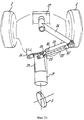
фиг. 1 схематически изображает перспективный вид трехколесного транспортного средства согласно настоящему изобретению;
фиг. 2a-2c изображают более подробно устройство наклона, применяемое в транспортном средстве, соответствующем фиг. 1;
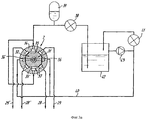
фиг. 3a схематически изображает чертеж, показывающий принцип устройства гидравлического средства, которое может быть использовано в устройстве наклона, показанном на фиг. 2;
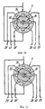
фиг. 3b изображает часть фиг. 3a в следующем положении;
фиг. 3c изображает часть фиг. 3a, показанную в еще одном следующем положении;
фиг. 3d изображает деталь альтернативного варианта выполнения варианта воплощения изобретения, показанного на фиг. 3b; и
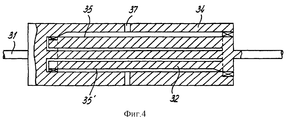
фиг. 4 изображает вид сбоку с частичным разрезом измерителя крутящего момента.In these drawings:
FIG. 1 schematically depicts a perspective view of a three-wheeled vehicle according to the present invention;
FIG. 2a-2c depict in more detail the tilt device used in the vehicle of FIG. 1;
FIG. 3a schematically depicts a drawing showing the principle of a hydraulic device that can be used in the tilt device shown in FIG. 2;
FIG. 3b is a portion of FIG. 3a in the following position;
FIG. 3c shows part of FIG. 3a shown in yet another following position;
FIG. 3d depicts a detail of an alternative embodiment of the embodiment of the invention shown in FIG. 3b; and
FIG. 4 is a partially cutaway side view of a torque meter.
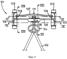
Фиг. 5 изображает схематический вид сверху, частично в разрезе, части транспортного средства, оснащенного устройством согласно изобретению;
фиг. 6 изображает вид сечения по линии VI-VI на фиг. 1;
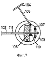
фиг. 7 изображает вид сечения по линии VII-VII на фиг. 1;
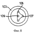
фиг. 8 изображает вид сечения по линии VIII-VIII на фиг. 1;
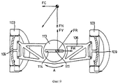
фиг. 9 изображает вид сечения по линии IX-IX на фиг. 1, когда транспортное средство находится в первом положении;
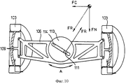
фиг. 10 изображает вид соответствующий фиг. 9, когда транспортное средство находится во втором положении;
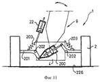
фиг. 11 изображает вид сзади транспортного средства, показанного на фиг. 1, согласно еще одному альтернативному варианту воплощения изобретения;
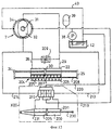
фиг. 12 изображает схему гидравлического устройства, которое может применяться в альтернативном варианте, показанном на фиг. 11; и
фиг. 13 изображает деталь XIII на фиг. 12 в сечении.FIG. 5 is a schematic top view, partially in section, of a part of a vehicle equipped with a device according to the invention;
FIG. 6 is a sectional view taken along line VI-VI of FIG. 1;
FIG. 7 is a sectional view taken along line VII-VII of FIG. 1;
FIG. 8 is a sectional view taken along line VIII-VIII of FIG. 1;
FIG. 9 is a sectional view taken along line IX-IX of FIG. 1 when the vehicle is in the first position;
FIG. 10 is a view corresponding to FIG. 9 when the vehicle is in a second position;
FIG. 11 is a rear view of the vehicle of FIG. 1, according to yet another alternative embodiment of the invention;
FIG. 12 is a diagram of a hydraulic device that may be used in the alternative embodiment shown in FIG. eleven; and
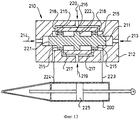
FIG. 13 depicts detail XIII in FIG. 12 in section.
На фиг. 1 схематично изображено трехколесное транспортное средство 1. Указанное транспортное средство имеет два задних колеса 2, которые расположены в осевом направлении на некотором расстоянии друг от друга по обе стороны от продольной оси транспортного средства 1. Также показано переднее колесо 3, расположенное в центре. Два задних колеса 2 приводятся двигателем. Силовой установкой 4 является обычный двигатель внутреннего сгорания, расположенный между задними колесами 2, и его расположение схематически показано на фиг. 2. Как показано на фиг. 1, переднее колесо 3 крепится к секции 9 при помощи передней вилки 5, которая вращается вокруг оси 11, находящейся в вертикальной плоскости. Передняя вилка 5 направлена так, что по направлению движения ось 11 достигает грунта в точке 43, расположенной впереди точки контакта 42 колеса 3 с грунтом. Соединение смонтировано между рулевым колесом 6 и передней вилкой 5. Указанное соединение включает измеритель момента поворота руля или измеритель силы поворота руля 7. Рулевое колесо 6 может соединяться непосредственно с передней вилкой 5, как, например, у обычного велосипеда. Необязательно соединение может осуществляться через передающие средства, например рулевые тяги, тросы управления или тому подобные (не показаны). Соединение также может быть выполнено в гидравлическом или электрическом варианте и т.д. Тип измерителя 7 зависит от выбранного соединения. Например, указанный измеритель момента поворота руля 7 устроен так, как показано более подробно на фиг. 3. Водитель может сидеть за рулевым колесом 6 на сидении 8. Кроме того, транспортное средство 1, показанное на фиг. 1, состоит из двух секций: передней секции 9 и задней секции 10, которые сконструированы так, что они могут наклоняться относительно друг друга вокруг продольной оси транспортного средства 1. Переднее колесо 3, передняя вилка 5, рулевое колесо 6, измеритель момента поворота руля 7 и сидение 8 расположены в передней секции 9. Два задних колеса 2 и двигатель 4 расположены в задней секции 10. Два задних колеса 2 приводным способом соединены через обычный дифференциал друг с другом и с двигателем 4. В другом варианте воплощения изобретения двигатель может быть смонтирован в наклонной части 9. Переднее колесо 3 может соединяться с остальной частью транспортного средства 1 так, что образуется так называемое рулевое управление со ступицей. In FIG. 1 schematically depicts a three-wheeled vehicle 1. The specified vehicle has two
Как показано более подробно на фиг. 2, наклоняющая труба 21, которая отступает назад от передней секции 9, проходит вдоль нижней стороны передней секции 9. Такая наклоняющая труба не вызывает необходимости проводить ее горизонтально. Центральная линия указанной наклоняющей трубы 21 представляет собой центральную продольную ось транспортного средства 1. Указанная наклоняющая труба 21 помещена так, что она может вращаться вокруг центральной линии транспортного средства в подшипниковой втулке (не показана) двигателя 4 в задней секции 10 транспортного средства 1. При помощи указанной вращающейся подшипниковой втулки наклоняющей трубы 21 передняя секция 9 может наклоняться влево и вправо вокруг центральной продольной оси транспортного средства 1, в то время как задняя секция 10 остается в неизменном положении. При наклоне передней секции 9 переднее колесо 3 будет наклоняться одновременно с ней в аналогичном направлении. As shown in more detail in FIG. 2, the
Для определения степени наклона, согласно изобретению, измеряются движение рулевого колеса, или сила поворота руля, или момент поворота руля, как описано более подробно и более конкретно со ссылками на фиг. 3. Собственно наклон может достигаться при помощи наклоняющего устройства, которое показано в деталях на фиг. 2. На ней показаны две комбинации двойного действия поршень/цилиндр 22, 22'. Свободный конец штока поршня 23 соединен с возможностью качания с крепежным выступом 24 двигателя 4. Свободный конец штока поршня 23' соединен с возможностью качания на некотором расстоянии от центральной оси наклоняющей трубы 21 с крепежным выступом 25, отступающим от наклоняющей трубы 21. На противоположном конце комбинации поршень/цилиндр 22, 22' соединены с возможностью качания друг с другом и с соединительным стержнем 26, другой конец которого соединен с возможностью качания с другим крепежным выступом 27 на секции 10 или секции 9; здесь указанный выступ 27 находится на двигателе 4. To determine the degree of inclination according to the invention, the movement of the steering wheel, or the steering force of the steering wheel, or the moment of rotation of the steering wheel are measured, as described in more detail and more specifically with reference to FIGS. 3. The actual inclination can be achieved using an inclination device, which is shown in detail in FIG. 2. It shows two dual-action combinations of piston /
Кроме того, цифрами 28, 28' и 29, 29' обозначены соединительные отверстия цилиндров комбинаций цилиндр/поршень 22 и 22', соответственно, для подсоединения к гидравлическому контуру, как, например, описано и показано более конкретно на фиг. 3. Отверстие 28 соединено непосредственно с отверстием 29'. Отверстие 28' соединено непосредственно с отверстием 29. Следовательно, между измерителем момента 7 и комбинациями цилиндр/поршень 22, 22' проходит не более двух линий. Однако отверстия 28, 28', 29, 29' не обязательно должны быть соединены как показано, и более чем две линии могут быть проведены между измерителем момента 7 и комбинациями цилиндр/поршень 22, 22'. Если давление в отверстии 28 выше, чем давление в отверстии 29, транспортное средство 1 будет наклоняться направо. Наклон влево будет происходить в обратной ситуации. Положение поршня 30, 30' показано прерывистой линией на фиг. 2 в каждом случае. In addition, the
При езде по прямой (фиг. 2а) два штока поршня 23, 23' находятся в максимально выдвинутом положении и оба поршня 30, 30' находятся в контакте с соответствующими стопорами (не показаны), которые определяют максимальное положение конца хода поршня. В указанном положении передняя секция 9 транспортного средства 1 находится в нейтральном положении, то есть указанная секция расположена вертикально и переднее колесо 3 также расположено вертикально и выровнено с положением для движения по прямой, то есть параллельно центральной продольной оси транспортного средства 1, и, таким образом, параллельно центральной оси наклоняющей трубы 21. Это положение может устанавливаться надежно и эффективно, поскольку в указанном положении два поршня 30, 30' находятся в полностью выдвинутом состоянии. На фиг. 2b показана ситуация, когда произведен наклон вправо. В этом случае поршень 30' комбинации 22' цилиндр/поршень движется, в то время как поршень 30, предпочтительно, остается на месте. Переднее колесо 3, соответственно, поворачивается вправо вокруг оси 11. Одновременно переднее колесо 3 наклоняется вправо вместе с секцией 9. На фиг. 2b поршень 30' показан в полностью задвинутом положении. Это соответствует положению максимального наклона направо. Будет ясно, что поршнем 30' также могут заниматься промежуточные положения, соответствующие промежуточным наклонным положениям. When driving in a straight line (Fig. 2a), two
На фиг. 2c показана ситуация, когда передняя секция 9 наклонена в другую сторону, то есть налево на чертеже. Поршень 30 теперь движется от полностью выдвинутого положения, показанного на фиг. 2a, тогда как поршень 30', предпочтительно, остается в неизменном положении. Вновь переднее колесо 3 поворачивается соответственно, то есть влево. In FIG. 2c shows a situation where the
Нейтральное положение, показанное на фиг. 2a, принимается автоматически от наклонного положения, если, например, максимальное гидравлическое давление воздействует на каждый из поршней 30, 30'. В таком случае поршни 30, 30' автоматически приводятся в полностью выдвинутое положение, показанное на фиг. 2a, благодаря преобладающей разности в площади поверхности на каждой стороне каждого поршня в результате наличия штоков поршней 23 и 23', соответственно. Путем уравновешивания разницы давлений на поршни 30, 30' через отверстия 28, 29 и, соответственно, 28', 29' может обеспечиваться соответствующее движение поршней 30 или 30' в зависимости от направления и значения силы поворота руля или момента поворота руля и/или движения рулевого колеса, и/или углового вращения переднего колеса 3 вокруг оси 11. The neutral position shown in FIG. 2a is automatically taken from an inclined position if, for example, the maximum hydraulic pressure acts on each of the
Конечно, также могут применяться наклоняющие устройства, отличающиеся от изображенного на фиг. 2. Например, узлы 22, 22' цилиндр/поршень могут замещаться одним или более линейными двигателями другого типа, такого как, например, двигателем электрического или магнитного действия. Также возможно, например, выбрать применение вращающегося приводного элемента, который может, например, включаться в наклоняющую трубу 21. Пневматический принцип действия, например, также может применяться вместо гидравлического принципа действия. Комплект комбинаций 22, 22' цилиндр/поршень может также заменяться одной комбинацией цилиндр/поршень, поршень 30 которой занимает центральное положение между двумя конечными точками хода поршня, когда передняя секция 9 находится в нейтральном, то есть не наклонном положении. Однако для точного и надежного получения нейтрального (для движения по прямой линии) положения предпочтителен альтернативный вариант воплощения изобретения, изображенный на фиг. 2. Of course, tilting devices other than those shown in FIG. 2. For example, the cylinder /
Гидравлическое управление, которое в особенности преимущественно в отношении альтернативного варианта, показанного на фиг. 2, теперь будет описано более подробно со ссылками на фиг. 3 и 4. На фиг. 4 показан узел, включающий измеритель 7 момента поворота руля и рулевую тягу 31. Измеритель 7 момента поворота руля содержит цилиндрический корпус 34, который одним концом соединен с рулевой тягой 31 так, что он не может вращаться. Рулевой ползун 32 помещен в указанный корпус 34. На свободном конце корпуса 34 указанный рулевой ползун 32 соединен с рулевой тягой 31 так, что он не может вращаться, и окружает рулевую тягу 31 с зазором между ними. Наружная окружность рулевого ползуна имеет серию плоскостей 35, 35', 36, 36', что более ясно можно видеть на фиг. 3. Если на рулевую тягу 31 воздействует момент, указанная рулевая тяга поворачивается, в результате чего корпус 34 будет поворачиваться относительно рулевого ползуна 32. На фиг. 3 в сечении показан измеритель рулевого момента 7, встроенный в гидравлическое устройство, показанное схематически. На цилиндрической периферической поверхности рулевой ползун 32 имеет два комплекта диаметрально противоположных плоскостей, причем плоскости 35, 35' шире плоскостей 36, 36'. Восемь отверстий 37, выполненных в корпусе 34, открыты в полость корпуса и, как видно в сечении корпуса 34, они распределены под одинаковыми углами по всей окружности. Как показано на чертеже, верхнее и нижнее отверстия 37 сообщаются с нагнетательным насосом 38 и накопителем давления 39. В показанном варианте воплощения изобретения корпус 34 и рулевой ползун 32 в сечении симметричны. Асимметричный вариант также возможен, и в этом случае накопитель соединяется с корпусом 34 только в одной точке и отверстия 28, 29' и, соответственно, 28', 29 соединяются с корпусом 34 общей линией. Hydraulic control, which is especially advantageous with respect to the alternative embodiment shown in FIG. 2 will now be described in more detail with reference to FIG. 3 and 4. In FIG. 4 shows a assembly including a
Оба отверстия 37, расположенные в горизонтальной средней плоскости на чертежах, соединены с выпускным средством 40, которое (необязательно) через шестеренчатый насос 41 сообщается с накопительной емкостью 42. Преобладающее давление в указанной накопительной емкости 42 для жидкости ниже, чем преобладающее давление в накопителе давления 39. Шестеренчатый насос 41, которым можно пренебречь, вращается со скоростью, пропорциональной скорости транспортного средства. Чем быстрее вращается шестеренчатый насос 41, тем ниже будет противодавление, с которым шестеренчатый насос воздействует на жидкость, протекающую из корпуса 34 по линии 40. При медленном вращении шестеренчатого насоса 41 жидкость будет испытывать большее сопротивление, в результате чего действие наклоняющего устройства будет соответственно задерживаться. Это дает преимущество, например, при движении к месту парковки и от него, которое связано с большими значениями поворота рулевого колеса или большими рулевыми моментами/рулевыми силами, когда наклон секции 9 транспортного средства нежелателен и даже вызывает неудобство. Для ограничения действия наклоняющего устройства при движении с относительно низкими скоростями может также быть выбрано вместо шестеренчатого насоса 41 другое средство. Например, вместо шестеренчатого насоса 41 может быть выбран управляемый скоростью отсечной клапан, который при уменьшении скорости закрывается в нарастающей степени. Both
Другие отверстия 37, показанные на чертежах, соединены с соответствующими отверстиями в комбинациях цилиндр/поршень 22 и 22' соответственно (см. фиг. 2).
Если применяется шестеренчатый насос 41, предпочтительно включить в конструкцию обратный клапан 43, как показано, для предотвращения возрастания давления и/или образования вакуума в насосе и в контуре вследствие действия шестеренчатого насоса 41. If a
Гидравлическое устройство, показанное на фиг. 3, действует следующим образом:
На фиг. 3а показано нейтральное положение рулевого ползуна 32, находящегося внутри корпуса 34, которое соответствует положению транспортного средства 1 при движении по прямой линии. Можно ясно видеть, что плоские части соединительного паза 35 рулевого ползуна 32 достаточно велики, чтобы обеспечивать сообщение отверстий 28, 28' и 29, 29' с накопителем давления 39. Следовательно, на стороны обоих поршней 30, 30' (фиг. 2) воздействует одинаковое преобладающее давление, и, таким образом, они находятся в полностью выдвинутом положении, показанном на фиг. 2. Плоскости 36, 36' имеют такую небольшую величину, что в нейтральном положении рулевого ползуна 32 они сообщаются только с выпускной линией 40. Указанная выпускная линия 40 не соединяется через измеритель управляющего момента 7 с накопителем давления 39.The hydraulic device shown in FIG. 3, acts as follows:
In FIG. 3a shows the neutral position of the steering
Когда рулевой ползун 32 слегка поворачивается (например, направо, как показано на фиг. 3b), соединение между отверстиями 28, 28', 29, 29' с накопителем 39 сохраняется. Однако жидкость теперь может поступать также в отверстия соединительного паза 36, 36' и, таким образом, в линию 40. Положение рулевого ползуна 32 относительно корпуса 34 в этой ситуации показано более подробно на фиг. 3d. Следовательно, в этом положении происходит "утечка" жидкости из накопителя 39 в линию 40. Следовательно, потеря давления возрастает в пределах, которые зависят от степени, в которой может вытекать жидкость. При помощи этого возможно надежное управление скоростью наклона. При дальнейшем повороте вправо (фиг. 3c) отверстия 28 и 29 отсоединяются от накопителя давления 39. Теперь они сообщаются только с линией 40 и, соответственно, в указанных линиях возрастает потеря давления, в результате чего поршни начнут движение. При этом происходит наклон транспортного средства 1. Следовательно, разница давлений на поршень 30 и поршень 30' будет достаточно большой для движения от положения, показанного на фиг. 2a, в направлении положения, показанного на фиг. 2c и 2b соответственно. Пока поршень 30 или поршень 30' движется, рулевой ползун 32 будет медленно вращаться назад, в положение, показанное на фиг. 3b, пока необходимая управляющая сила или управляющий момент или необходимое движение рулевого колеса автоматически не уменьшится в результате увеличения наклона транспортного средства. Как только будет достигнуто наклонное положение равновесия, что связано с преобладающими условиями для продолжения наклона, будет преобладать ситуация, показанная на фиг. 3b, в которой малая управляющая сила или движение рулевого колеса все еще должно обеспечиваться рулевым колесом 6. Как только рулевое колесо 6 будет повернуто в противоположном направлении или отпущено, рулевой ползун 32 займет положение, показанное на фиг. 3a, или будет повернут за эту точку в противоположном направлении так, что поршни 30, 30' (фиг. 2) возвратятся в первоначальное положение, как показано на фиг. 2a. When the steering
Конечно, для осуществления изобретения также могут применяться варианты, отличающиеся от показанных и описанных здесь. Например, обычный рулевой механизм с силовым приводом также может встраиваться между рулевым колесом 6 и передним колесом 3 для образования части управляющей силы, требуемой для управления транспортным средством, особенно с низкими скоростями движения. Указанный механизм может, например, соединяться с тем же накопителем давления 39, нагнетательным насосом 38 и накопительной емкостью 42 для жидкости, как показано на фиг. 3a. Кроме того, может также применяться другой вариант измерителя управляющего момента, отличающийся от варианта, показанного на фиг. 3. Кроме того, также, например, можно снабдить транспортное средство более чем одним управляемым по направлению колесом, которое движется вместе с наклоняемой секцией транспортного средства. Измеритель момента управления 7, показанный на фиг. 3, может также применяться для электронного управления. Для этой цели плоские части 35, 35' и 36, 36' могут выполняться в качестве скользящих контактов, и положения отверстий 37 определяют различные точки электрических контактов с источником электроэнергии, заземлением и точки соединения с одним или более линейных двигателей. Вместо измерения момента измеритель 7 может также предназначаться для измерения силы. Может использоваться преобладающая нормальная сила между рулевым колесом и передней вилкой. Указанная сила прямо пропорциональна прилагаемому моменту управления. Отсечной клапан, который может скользить в продольном направлении относительно рулевой тяги, может помещаться в корпус, снабженный отверстиями, при этом отсечной клапан управляет открыванием и перекрытием отверстий в качестве функции прилагаемой управляющей силы. Отсечной клапан может удерживаться в нейтральном положении при помощи, например, пружин. На основании фиг. 3 специалист в данной области техники легко сможет создать управляемый электронным способом измеритель управляющего момента такого типа, опираясь на свои знания. Однако предпочтительно получить гидравлическое устройство, обладающее большей надежностью. Такой уровень надежности важен, в частности, для автомобилей. Of course, variations other than those shown and described herein may also be used to practice the invention. For example, a conventional power driven steering mechanism may also be integrated between the steering wheel 6 and the front wheel 3 to form part of the control force required to drive the vehicle, especially at low speeds. Said mechanism can, for example, be connected to the
На фиг. 5 изображена часть транспортного средства 101. На фиг. изображена центральная рама 102, к которой крепится кузов (не показан), сидения, педали управления и другие средства, монтаж которых подробно не показан. Рама 102 перемещается на колесах. Только два передних колеса 103 показаны на фиг. 5. Эти колеса (необязательно) могут быть задними колесами. Специалисту в данной области техники будет понятно, что транспортное средство 101 также подвешено на одном или более приводных задних колес, которые на фиг. 5 не показаны. Указанным одним или более колес может быть единственное, например, расположенное по центру, колесо или два колеса с шириной колеи, которая, например, сравнима с шириной колеи передних колес 103. Транспортное средство 101 может быть двухосным или многоосным. Передние колеса 103, как показано, установлены на одной оси. Когда два колеса расположены относительно близко рядом друг с другом на одной или по существу на одной оси (например, с промежутком между ними, который не больше, чем несколько размеров ширины колеса), такие колеса не могут рассматриваться в рамках настоящего изобретения как одно колесо. Фактически, количество колес не имеет значения, если транспортное средство удерживается этими колесами в равновесии. Это означает, что транспортное средство должно быть по меньшей мере так называемым трехколесным транспортным средством. In FIG. 5 shows a portion of a
На фиг. 5 также изображено рулевое колесо 104, вращающееся вокруг рулевой колонки 105. Датчик управляющей силы (не показан) или датчик движения рулевого колеса (не показан) может устанавливаться на рулевой колонке 105 или в любом другом пригодном месте. Датчик может быть типа, описанного относительно фиг. 4. Данные, выдаваемые таким датчиком, используются для контроля степени наклона транспортного средства внутрь окружности поворота. Данные от указанного датчика передаются к так называемому устройству наклона транспортного средства (не показано), при помощи которого наклоняемая секция транспортного средства наклоняется с силовым содействием (в нужном направлении и в необходимых пределах) относительно ненаклоняемой секции. Например, устройство наклона транспортного средства имеет одну или более гидравлических или пневматических комбинаций поршень/цилиндр или другие приводные элементы, которые могут удлиняться и укорачиваться, или вращающиеся приводные элементы для достижения управляемого наклона с силовым содействием двух секций относительно друг друга. Наклоняющие устройства могут быть такого типа, который показан на фиг. 2. На конце рулевой колонки 105, удаленном от рулевого колеса 104, находится широко распространенная трансмиссия для бокового движения задней рулевой тяги 106. Применяется также передняя рулевая тяга 107, которая соединена обычным способом при помощи шарнирных соединений 108 со ступицей 109 каждого колеса 103. Совокупность рулевых тяг 106 и 107 и соединений 108 образует средство для управления колесами 103, которое обычно для автомобилей. На фиг. 7 показано более подробно, как рулевая колонка 105 соединяется при помощи рулевой трансмиссии 110 с задней рулевой тягой 106. В этом конкретном случае выбрана обычная реечная трансмиссия. Как можно видеть, в частности на фиг. 5, рама 102 поддерживается относительно рулевых тяг 106, 107 при помощи балки 111. Как можно видеть, в частности на фиг. 7, указанная балка 111 проходит через заднюю рулевую тягу 106 и через переднюю рулевую тягу 107. Для этого передняя рулевая тяга 107 имеет вертикальный паз 112. Как можно видеть на фиг. 9 и 10, задняя рулевая тяга 106 снабжена вращающимся элементом 113, который вращается вокруг продольной оси, параллельной продольной оси транспортного средства (то есть соответственно двойной
стрелке А, лежащей в плоскости чертежа на фиг. 9 и 10). Паз 114 выполнен в указанном вращающемся элементе 113, и в этот паз заключена балка 111 с возможностью скольжения. Как показано на фиг. 6, балка 111 имеет круглое поперечное сечение в том месте, где указанная балка проходит через паз 112. Как можно видеть на фиг. 9 и 10, балка 111 имеет прямоугольное сечение в том месте, где указанная балка проходит через паз 114. Балка 111, таким образом, может вращаться вокруг ее продольной оси относительно паза 112, но не может вращаться вокруг указанной продольной оси относительно вращающегося элемента 113. Когда транспортное средство движется по прямой линии (фиг. 9), паз 114 будет горизонтальным. При движении по изогнутой линии (изогнутой вправо, как показано на фиг. 10), паз 114 займет наклонное положение. При движении по прямой линии балка 111 в целом центруется относительно оси вращения вращающегося элемента 113. Балка 111 удерживается по центру при помощи придания пригодного угла наклона колеса 103 относительно, например, передней рулевой тяги 107. При повороте рулевого колеса 104 (направо на фиг. 9) задняя рулевая тяга будет перемещаться налево на фиг. так, что балка 111 соответственно перемещается направо от ее центрального положения. Наклон направо произведен. Горизонтальная сила FH должна образовываться рулевым колесом 104 для получения необходимого смещения задней рулевой тяги 106 влево. Это требует воздействия момента на рулевое колесо 104, значение и направление которого может измеряться датчиком управляющей силы (не показан), который уже описан выше и который, например, установлен на рулевой колонке 105. Горизонтальная сила FH вместе с вертикальной силой FV (сила противодействия силе тяжести) определяет результирующую силу FR, которая первоначально направлена под углом к продольному направлению паза 114. Устройство наклона транспортного средства (не показано) управляется при помощи сигналов от датчика управляющей силы для осуществления наклона наклоняемой секции 102 транспортного средства 101 вправо вокруг продольной оси. Следовательно, вращающийся элемент 113 будет поворачиваться вокруг своей оси; при повороте руля направо он будет поворачиваться до достижения положения равновесия, показанного на фиг. 10. В результате указанного наклона результирующая FR будет нарастать до положения, перпендикулярного относительно продольного направления паза 114, в результате чего необходимая управляющая сила, которая должна прилагаться к рулевому колесу 104, уменьшается с таким же темпом до нуля, когда достигается наклонное положение равновесия, датчик управляющей силы отслеживает с тем же темпом непрерывно уменьшающуюся управляющую силу, воздействующую на рулевое колесо 104, и будет соответственно управлять устройством наклона транспортного средства. Когда, при создании наклона при постоянной скорости и радиусе поворота (и постоянном боковом ветре и других нагрузках), управляющая сила, воздействующая на рулевое колесо 104, падает до нуля, устройство наклона транспортного средства будет поддерживать наклонное положение равновесия наклоняемой секции. Если рама 102 поддерживается в задней части расположенным по центру единственным задним колесом (трехколесная конфигурация), указанное расположенное по центру заднее колесо может наклоняться вместе с рамой 102. Если транспортное средство, например четырехколесное, где задняя часть рамы 102 поддерживается двумя колесами с шириной колеи, которая соответствует ширине колеи передних колес 103, то будет возможно избрать свободно вращающийся элемент для соединения рамы 102 с указанными задними колесами, при этом указанный вращающийся элемент также свободно вращается вокруг оси, параллельной продольной оси транспортного средства 101, относительно задней оси. Конечно, специалистам, знакомым с предшествующим уровнем техники, будут очевидны другие решения. При помощи устройства обратной подачи (например, основанного на рулевых механизмах с усилением для транспортных средств) возможно добиться искусственными средствами, чтобы управляющая сила все еще прилагалась к рулевому колесу 104, даже в положении наклонного равновесия (фиг. 10) так, что водитель сохраняет "ощущение руля" при прохождении поворота. Для этого можно, например, встроить в рулевую колонку 105 пригодный торсионный элемент. Необязательно, можно обеспечить неполный наклон наклоняемой секции транспортного средства до достижения положения равновесия при прохождении поворота. Следовательно, результирующая сила FR никогда не будет окончательно перпендикулярной продольному направлению паза 114. Следовательно, водитель должен продолжать прилагать силу к рулевому колесу 104, даже при прохождении поворота с постоянным радиусом при постоянной скорости движения. Специалистам в данной области техники будет понятно, что отклонение наклонного положения равновесия от реального наклонного положения при прохождении поворота может следовать прогрессирующей кривой так, что при более быстром движении и/или при большей кривизне поворота водитель отмечает обратную реакцию руля, соответствующую условиям движения. Этот тип механизма обратной реакции руля особенно прост и, например, не требует торсионного элемента, который должен приводиться в действие извне, или чего-то подобного.In FIG. 5 also depicts a
arrow A lying in the plane of the drawing in FIG. 9 and 10). The
Наконец, на фиг. 8 изображено положение задней рулевой тяги и передней рулевой тяги 107 относительно ступицы 109. Будет понятно, что задняя рулевая тяга 106 находится на одной линии со ступицей 109 и с точкой контакта колеса с дорогой. Необходимый угол наклона передней оси достигается при помощи передней рулевой тяги 107. Finally, in FIG. 8 shows the position of the rear tie rod and the
При наклоне рамы 102 балка 111 будет двигаться вверх и вниз относительно паза 112 в передней рулевой тяге 107. When the
Таким образом, возможно управлять наклоном рамы 102 вокруг оси, параллельной продольной оси транспортного средства 101, как прямой функции движения рулевого колеса или управляющей силы, в результате чего более нет необходимости в, например, датчиках ускорения. Thus, it is possible to control the inclination of the
По сути, нет необходимости приводить вращающийся элемент 113 в плоскость движения задней рулевой тяги. Важно то, что рама 102 направляется вдоль, предпочтительно, прямой направляющей поверхности, которая может занимать горизонтальное или наклонное положение относительно ненаклоняемой секции транспортного средства 101 (здесь: рулевые тяги 106 и 107). In fact, there is no need to bring the
Составные элементы, показанные на фиг. 11, 12 и 13, которые соответствуют аналогичным элементам на фиг. 1-4, имеют аналогичные обозначения. The constituent elements shown in FIG. 11, 12 and 13, which correspond to similar elements in FIG. 1-4 have the same designations.
На фиг. 11 показан в особенности преимущественный вариант ненаклоняемой секции 10 транспортного средства 1. С этим вариантом негативные эффекты пружинной подвески 10 задних колес 2 при наклоне секции 9 транспортного средства могут быть ограничены до приемлемых пределов или даже устранены. Это возможно без необходимости выбора особенно сложной конструкции пружинной подвески колес 2. Общий режим работы транспортного средства 1 также может быть усовершенствован в варианте, соответствующем фиг. 11. Вариант воплощения изобретения, соответствующий фиг. 11, основан на понимании того, что существует возможность уменьшения или устранения негативного эффекта пружинной подвески задних колес 2 при наклонном движении наклоняемой секции 9 путем образования момента при помощи средства с силовым приводом, с колесами 2, моменту которых противостоит противодействующий момент, образуемый ненаклоняемой секцией 10 при наклоне наклоняемой секции 9. Этот противоположный момент, который должен образовываться с силовым содействием колесами 2, может иметь такое же значение, как и противодействующий ему момент. Однако в некоторых обстоятельствах это не является абсолютно необходимым. Противоположный момент образуется с помощью приводного элемента 200, который, в этом случае, является узлом двойного действия поршень/цилиндр. Каждое колесо 2 соединено при помощи поворотного рычага 201 с приводным элементом 200. Каждый поворотный рычаг 201 соединен с возможностью поворота шарниром 202 с ненаклоняемой секцией 10 транспортного средства. При помощи удлинения или укорочения приводного элемента 200 может достигаться поворот поворотных рычагов 201 в противоположных направлениях относительно шарниров 202 для образования, таким образом, противоположного момента. Пружинная подвеска колес 2 обеспечивается при помощи элементов пружина/амортизатор 203, которые могут быть обычного типа, и здесь показаны лишь схематично. Указанные элементы 203 соединены с одной стороны с соответствующим поворотным рычагом 201 и с ненаклоняемой секцией 10 транспортного средства 1. In FIG. 11 shows a particularly advantageous embodiment of the non-tilting section 10 of the vehicle 1. With this embodiment, the negative effects of the spring suspension 10 of the
Приводной элемент 200, преимущественно, имеет такую конструкцию, что действие элементов 203 не подвергается воздействию, или подвергается как можно меньшему воздействию при приведении в действие указанного приводного элемента. Приводной элемент 200 должен, таким образом, предпочтительно, иметь такую конструкцию, чтобы движения колес 2 относительно ненаклоняемой секции 10 вследствие, например, неровностей на дороге, допускались даже в момент времени, когда преобладает противоположный момент. Это означает, что сжатие и разгрузка элементов 203 вследствие таких движений колес 2 допускаются элементом 200. В случаях гидравлического или пневматического вариантов действия элемента 200 вариант воплощения изобретения, соответствующий фиг. 12, в этом контексте предпочтителен. The
Измеритель управляющего момента или измеритель управляющей силы 7, показанный на фиг. 12, является упрощенным вариантом альтернативных вариантов воплощения изобретения, соответствующих фиг. 3 и 4. Специалистам, знакомым с предшествующим уровнем техники, будет понятно, как измеритель управляющей силы или управляющего момента 7, соответствующий фиг. 3 или 7, или другие его варианты могут применяться в варианте воплощения изобретения, соответствующем фиг. 12. Измеритель 7 в первую очередь используется для управления приводным элементом 22 устройства наклона транспортного средства. Конструкция указанного приводного элемента 22 отличается от конструкции элемента, показанного на фиг. 2. Специалистам в данной области техники будет понятно, как привод устройства наклона транспортного средства, соответствующий фиг. 2, может применяться в варианте воплощения изобретения, соответствующем фиг. 12. В варианте, соответствующем фиг. 12, для получения эффекта наклона было избрано применение единственного узла двойного действия поршень/цилиндр 22. The control torque meter or
Указанный узел поршень/цилиндр 22 последовательно соединен с предварительно натянутым узлом 204, при помощи которого узел поршень/цилиндр 30 притянут в нейтральное среднее положение. В показанном альтернативном варианте для этого образован возвратный элемент 204 из двух пружин 207, 206, расположенных с двух сторон от тарелки 207, которая соединена при помощи штока 208 с выступами 24, 25. Конечно, применение альтернативных элементов для возврата привода 22 устройства наклона в его нейтральное, среднее положение, также возможно. Дроссельный элемент 209 с регулируемой установкой встроен между линиями 28, 29, которые ведут к приводному элементу 22. The specified piston /
Управляющий элемент 210 также встроен в гидравлический контур на фиг. 12. Указанный управляющий элемент показан более подробно на фиг. 13. Измеритель 7 контролирует положение управляющего элемента 210 для того, чтобы таким образом управлять приводным элементом 200. The
Управляющий элемент 210 показан более подробно на фиг. 13. Указанный управляющий элемент 210 имеет корпус 212, который имеет выемку, в которой тело 211 может перемещаться справа налево и наоборот (на чертеже). Движение указанного тела 211 управляется при помощи разницы давлений, которые воздействуют на его концы. Указанная разница давлений регулируется при помощи гидравлических линий 213 и 214 способом, соответствующим созданию разницы давлений при помощи линий 28 и 29. Кроме того, тело 211 несет на своей периферической поверхности отсечные элементы 215 и управляющий элемент 216, находящийся между ними. В результате движения тела 211 отсечные элементы 215 открывают одно из впускных отверстий 217, 218, одновременно одно из других впускных отверстий 217, 218 закрывается. Впускные отверстия 217 соединены с линией 219, в которой давление, образуемое насосом 38, преобладает. Впускные отверстия 218 соединены с линией 220, в которой преобладает давление, заметно отличающееся от давления, преобладающего в линии 219 (ниже в этом варианте). В принципе, в показанном иллюстративном варианте линия 220 теряет давление, поскольку указанная линия открывается в масляный резервуар 42. Следовательно, в результате движения тела 211 будет создана разница давлений на управляющий элемент 216 так, что образуется сила, которая противостоит силе, воздействующей на тело 211 вследствие разницы давлений в линиях 213 и 214. Следовательно, тело 211 будет в каждом случае занимать положение равновесия в зависимости от разницы давлений, образованных линиями 213, 214 и, соответственно, 219, 220. Путем изменения соотношения площади поверхности концов 221 тела 211 и площади поверхности 222 управляющего элемента 216 существует возможность использовать единственный общий источник давления (насос 38 и накопитель давления) для того, чтобы установить степень смещения тела 211 до положения его равновесия. Таким образом, степень открывания впускного отверстия 218 и перекрытия впускного отверстия 218 и наоборот может регулироваться. Поскольку камеры с обеих сторон управляющего элемента 216 соединены соответствующими линиями 223, 224 с камерами с обеих сторон поршня 225 элемента 200, сила будет последовательно воздействовать на поршень 225 за счет разницы давлений на торцевые поверхности 221 и, следовательно, указанный поршень 225 будет также занимать положение равновесия благодаря разнице давлений на торцевые поверхности тела 211 и на управляющий элемент 216. Разница давлений на торцевые поверхности тела 211 управляется образующейся управляющей силой/управляющим моментом, благодаря чему также контролируется степень наклона наклоняемой секции 9 транспортного средства 1. The
Если правое (на фиг. 11) колесо 2 наталкивается на неровность на поверхности дороги и в результате подвергается воздействию направленной вверх (на фиг. ) силы, элемент 225 на фиг. 13 первоначально будет подвержен силе, направленной влево на фиг. Следовательно, давление в линии 224 увеличивается и в результате разного давления устанавливается разница давлений на управляющий элемент 216. Если разница давлений на торцевые поверхности 221 тела 211 остается неизменной, указанное тело 211 будет, следовательно, двигаться в его продольном направлении в новое положение равновесия. Таким образом, противоположный момент может продолжительно сохраняться при помощи элемента 200 при наклонном движении наклоняемой секции 9 транспортного средства 1, в то время как колеса 2 могут следовать неровностям на поверхности дороги 226 при помощи упругого и амортизирующего действия подвески 203. If the right wheel (in FIG. 11) of the
В качестве примера действие элемента 210 может быть описано следующим образом. Когда управляющий момент воздействует на рулевое колесо 6 в соответствии с вхождением транспортного средства 1 в поворот, разница давления будет производиться между линиями 213 и 214 при помощи измерителя управляющего момента 7. Следовательно, тело 211 движется от его нейтрального, среднего положения, в котором оба впускных отверстия 217 закрыты, например, направо на фиг. При этом движении левое впускное отверстие 217 на фиг. остается закрытым, в то время как правое впускное отверстие 217 на фиг, открыто. Одновременно левое впускное отверстие 218 на фиг. остается открытым, в то время как правое впускное отверстие 218 на фиг закрыто. Следовательно, давление, действующее на правую сторону управляющего элемента 216, будет увеличиваться, противодействуя движению тела 211 вправо. Чем дальше тело 211 движется вправо (на фиг.), тем больше открывается правое (на фиг.) впускное отверстие 217 и одновременно правое (на фиг.) впускное отверстие 218 закрывается и в результате тем больше будет противодействующее давление на правую сторону управляющего элемента 216. В результате тело 211 достигнет положения равновесия. Благодаря тому, что разница давлений, воздействующая на управляющий элемент 216, одновременно воздействует на поршень 225, противоположный момент, который (в значительной степени) нейтрализует эффект воздействия противоположного момента на подвеску 203, образуемого наклоняющим устройством и воздействующего на секцию 10, будет образован одновременно при помощи элемента 200. В результате наклона наклоняемой секции 9 транспортного средства 1 управляющий момент, прилагаемый к рулевому колесу 6, будет постепенно уменьшаться. Одновременно с уменьшением наклонного движения (22, 28, 29), разница давлений, воздействующая на тело 211, образованная линиями 213 и 214, будет также постепенно уменьшаться так, что тело 211 движется назад, влево (на фиг.), в его нейтральное положение, и противоположный момент, образуемый элементом 200, таким образом, также пропорционально уменьшается. As an example, the action of
Конечно, возможны другие способы для образования противоположного момента, который, например, имеет такую же величину (но направленный в противоположную сторону), как и реактивный момент, образуемый ненаклоняемой секцией 10 транспортного средства 1 при действии привода 22 наклоняющего устройства для наклона наклоняемой секции 9 транспортного средства 1. Например, управляющий элемент 210 может быть заменен электрическим эквивалентом. Предпочтительно, при таком устройстве должны быть предусмотрены меры для того, чтобы колеса ненаклоняемой секции 10 были способны продолжать неизменно следовать неровностям поверхности дороги 226, даже когда противоположный момент преобладает. Для этого предпочтительно сконструировать привод для образования противоположного момента таким образом, чтобы сжатие и разгрузка колес 2 ненаклоняемой секции 10 оставались возможными. Of course, other methods are possible for the formation of the opposite moment, which, for example, has the same magnitude (but directed in the opposite direction) as the reactive moment formed by the non-tilted section 10 of the vehicle 1 under the action of the
Элемент 210 применяется не только в транспортных средствах, которые имеют наклоняемую секцию 9. Его применение также возможно в обычных транспортных средствах, не имеющих наклоняющего устройства, например для образования противоположного момента при прохождении поворота для сохранения горизонтального положения транспортного средства, чтобы оно не наклонялось в наружном относительно изгиба поворота направлении, что является обычным для трех- или многоколесных транспортных средств, в то время как в этом случае также остается возможным сжатие и разгрузка отдельных колес без ограничения работы их индивидуальной подвески. Конечно, другие варианты устройства, показанного на фиг. 11-13, также возможны. Например, единственный узел поршень/цилиндр 200 при помощи которого совместно управляются рычаги 201, может быть заменен, например, двумя узлами поршень/цилиндр, каждый из которых затем соединяется одной стороной с ненаклоняемой секцией 10 и другим концом - с одним соответствующим рычагом 201 для управления рычагами 201 индивидуально. Фиг. 11-13 показывают, как приводной шток 230 выдвигается через две торцевые стенки 231 цилиндра узла поршень/цилиндр 200. Следовательно, поршень 225 имеет одинаковые площади поверхности на обеих его сторонах. Специалистам в данной области техники будет понятно, что также могут быть выбраны другие конструкции. Необходимый момент также может быть образован при помощи вращающегося элемента вместо узлов поршень/цилиндр (так называемые линейные исполнительные средства).
Сила может прилагаться к телу 211, например, механическими или электромагнитными средствами вместо средства, применяющего разницу давлений. Механический способ может быть осуществлен, например, с применением вытягивающейся/сжимающейся пружины. Было бы преимущественно управлять движением тела 211 основываясь на силе, а не смещении. A force may be applied to the
Claims (19)
14.06.94 - по пп.1, 3 - 11;
18.04.95 - по пп.2, 14 - 19;
11.08.94 - по пп.12 и 13.Priority on points:
06/14/94 - according to claims 1, 3 - 11;
04/18/95 - according to PP.2, 14-19;
08/11/94 - according to paragraphs 12 and 13.
Applications Claiming Priority (6)
| Application Number | Priority Date | Filing Date | Title |
|---|---|---|---|
| NL9400142 | 1994-06-14 | ||
| WOPCT/NL94/00142 | 1994-06-14 | ||
| NL9401303A NL9401303A (en) | 1994-08-11 | 1994-08-11 | Self-stabilizing, steerable vehicle with at least three wheels |
| NL1000161A NL1000161C1 (en) | 1995-04-18 | 1995-04-18 | Self-stabilising, directionally controllable vehicle with at least three wheels |
| NL9401303 | 1995-04-18 | ||
| NL1000161 | 1995-04-18 |
Publications (2)
| Publication Number | Publication Date |
|---|---|
| RU97100735A RU97100735A (en) | 1999-02-10 |
| RU2156201C2 true RU2156201C2 (en) | 2000-09-20 |
Family
ID=27351094
Family Applications (1)
| Application Number | Title | Priority Date | Filing Date |
|---|---|---|---|
| RU97100735/28A RU2156201C2 (en) | 1994-06-14 | 1995-06-13 | Self-stabilizing direction-controlled vehicle with at least three wheels |
Country Status (13)
| Country | Link |
|---|---|
| US (1) | US5927424A (en) |
| EP (1) | EP0796193B1 (en) |
| JP (1) | JP2970940B2 (en) |
| KR (1) | KR100396040B1 (en) |
| CN (1) | CN1055268C (en) |
| AU (1) | AU685639B2 (en) |
| BR (1) | BR9507997A (en) |
| CA (1) | CA2193073C (en) |
| CZ (1) | CZ291142B6 (en) |
| DE (1) | DE69506129T2 (en) |
| ES (1) | ES2124549T3 (en) |
| PL (1) | PL177035B1 (en) |
| RU (1) | RU2156201C2 (en) |
Cited By (1)
| Publication number | Priority date | Publication date | Assignee | Title |
|---|---|---|---|---|
| RU2665016C1 (en) * | 2016-05-12 | 2018-08-24 | Алексей Александрович Казарцев | Active suspension of narrow vehicle |
Families Citing this family (57)
| Publication number | Priority date | Publication date | Assignee | Title |
|---|---|---|---|---|
| DE19717418C1 (en) * | 1997-04-25 | 1998-10-22 | Daimler Benz Ag | Multi-lane curve headed vehicle |
| CZ299099B6 (en) * | 1997-09-16 | 2008-04-23 | Brinks Westmaas B. V. | Tilting vehicle |
| NL1007045C2 (en) * | 1997-09-16 | 1999-03-25 | Brinks Westmaas Bv | Tilting vehicle. |
| NL1007532C2 (en) * | 1997-11-12 | 1999-05-17 | Brinks Westmaas Bv | Tilting vehicle. |
| WO2002014136A2 (en) * | 2000-08-15 | 2002-02-21 | Mtd Products Inc | Ztr vehicle with a one-pump two-motor mechanism |
| US6685208B1 (en) | 2002-11-19 | 2004-02-03 | Ross L. Cowie | Balance system for an enclosed fore-and-aft wheeled vehicle |
| EP1620303B1 (en) * | 2003-05-02 | 2012-08-22 | James Christopher Dower | A three wheeled vehicle with tilting mechanism |
| WO2006041287A1 (en) * | 2004-10-12 | 2006-04-20 | Jan Willem Dan Bakker | Personal land and air vehicle |
| US8249775B2 (en) * | 2005-05-31 | 2012-08-21 | Brinks Westmaas B.V. | Self-balancing vehicle |
| US7648148B1 (en) | 2005-07-06 | 2010-01-19 | Bombardier Recreational Products Inc. | Leaning vehicle with tilting front wheels and suspension therefor |
| EP2431258B1 (en) | 2005-07-22 | 2015-09-09 | MTD Products Inc | Steering systems, steering and speed coordination systems, and associated vehicles |
| EP2086782B1 (en) | 2006-10-17 | 2019-07-10 | MTD Products Inc. | Vehicle control systems and methods |
| US8818700B2 (en) * | 2008-02-29 | 2014-08-26 | Daniel Moulene | Motorised vehicle with controlled inclination |
| US8136613B2 (en) | 2008-03-26 | 2012-03-20 | Mtd Products Inc | Vehicle control systems and methods |
| FR2933950B1 (en) * | 2008-07-21 | 2011-02-11 | Veleance | MECHANICAL INCLINATION CONTROL DEVICE |
| CN102378700B (en) * | 2009-03-30 | 2014-05-21 | 爱考斯研究株式会社 | Vehicle |
| US8123240B2 (en) | 2009-07-10 | 2012-02-28 | Bombardier Recreational Products Inc. | Control system for leaning vehicle |
| GB2476807B (en) * | 2010-01-08 | 2012-10-31 | David Andrew Gale | A vehicle |
| JP6022946B2 (en) * | 2010-02-26 | 2016-11-09 | セグウェイ・インコーポレイテッド | Apparatus and method for controlling a vehicle |
| ES2393907T3 (en) | 2010-05-17 | 2012-12-28 | Jaxa Networks | Vehicle that has variable track width |
| USD689794S1 (en) | 2011-03-21 | 2013-09-17 | Polaris Industries Inc. | Three wheeled vehicle |
| CA2830590C (en) | 2011-03-21 | 2017-08-22 | Polaris Industries Inc. | Three wheeled vehicle |
| JP5741278B2 (en) * | 2011-07-26 | 2015-07-01 | 株式会社エクォス・リサーチ | vehicle |
| WO2013043181A1 (en) | 2011-09-22 | 2013-03-28 | Mtd Products Inc | Vehicle control systems and methods and related vehicles |
| US8762002B2 (en) * | 2011-11-23 | 2014-06-24 | GM Global Technology Operations LLC | Steering system for three-wheeled vehicle |
| CN103162738B (en) * | 2011-12-19 | 2015-07-29 | 上海新世纪机器人有限公司 | For condition checkout gear and the method for balanced car with two wheels |
| SG11201500114RA (en) * | 2012-07-10 | 2015-02-27 | Gotech Internat Ltd | Steering and control systems for a three-wheeled vehicle |
| WO2014022315A2 (en) * | 2012-07-31 | 2014-02-06 | Helix Motors International, Inc. | Three-wheeled tilting vehicle |
| CN102849156B (en) * | 2012-09-20 | 2014-09-17 | 上海新世纪机器人有限公司 | Steering device of self-balance two-wheeler |
| DE102014201632B4 (en) | 2013-03-07 | 2021-09-02 | Ford Global Technologies, Llc | Laterally tiltable, multi-lane vehicle |
| DE102014201127B4 (en) | 2013-03-07 | 2022-02-03 | Ford Global Technologies, Llc | Side-tilting, multi-track vehicle |
| DE102014201630B4 (en) | 2013-03-07 | 2021-09-02 | Ford Global Technologies, Llc | Laterally tiltable, multi-lane vehicle |
| DE102014201670A1 (en) | 2013-03-07 | 2014-09-11 | Ford Global Technologies, Llc | Sideways inclinable, multi-lane vehicle |
| DE102014201668B4 (en) | 2013-03-07 | 2021-09-02 | Ford Global Technologies, Llc | Laterally tiltable, multi-lane vehicle |
| US9061564B1 (en) * | 2013-12-18 | 2015-06-23 | Automotive Research & Testing Center | Active vehicle with a variable inclination apparatus and method of using the same |
| CN104859765A (en) * | 2014-02-22 | 2015-08-26 | 倪明旺 | Deformable bridge frame of motor tricycle |
| DE102014217246B3 (en) | 2014-08-29 | 2015-12-24 | Ford Global Technologies, Llc | Stabilization arrangement for a tilting chassis of a vehicle |
| DE102014217386A1 (en) * | 2014-09-01 | 2016-03-03 | Ford Global Technologies, Llc | Method for operating a tilting chassis and active tilting suspension for a rail-bound vehicle |
| KR102422584B1 (en) * | 2014-09-02 | 2022-07-20 | 가부시끼 가이샤 구보다 | Harvester |
| US10076939B2 (en) | 2014-11-26 | 2018-09-18 | Ford Global Technologies, Llc | Suspension systems for laterally tiltable multitrack vehicles |
| US9925843B2 (en) | 2015-02-24 | 2018-03-27 | Ford Global Technologies, Llc | Rear suspension systems for laterally tiltable multitrack vehicles |
| US10023019B2 (en) | 2015-02-24 | 2018-07-17 | Ford Global Technologies, Llc | Rear suspension systems with rotary devices for laterally tiltable multitrack vehicles |
| JP6478743B2 (en) | 2015-03-23 | 2019-03-06 | 本田技研工業株式会社 | Moving body |
| DE102015007574A1 (en) | 2015-06-05 | 2016-12-08 | Technische Hochschule Nürnberg Georg Simon Ohm | Positioniergetriebe |
| JP6450267B2 (en) * | 2015-06-23 | 2019-01-09 | 本田技研工業株式会社 | Moving body |
| US9604683B2 (en) | 2015-06-28 | 2017-03-28 | Gregory W Kunsch | Rear engine, front wheel drive three wheeled vehicle |
| JP6408168B2 (en) | 2015-11-20 | 2018-10-17 | ヤマハ発動機株式会社 | vehicle |
| JP6646681B2 (en) | 2015-11-20 | 2020-02-14 | ヤマハ発動機株式会社 | Lean vehicle |
| EP3378748B1 (en) | 2015-11-20 | 2023-08-09 | Yamaha Hatsudoki Kabushiki Kaisha | Leaning vehicle |
| EP3378749B1 (en) | 2015-11-20 | 2020-04-01 | Yamaha Hatsudoki Kabushiki Kaisha | Leaning vehicle |
| DE202016004580U1 (en) * | 2016-07-25 | 2016-10-27 | Liebherr-Werk Ehingen Gmbh | Axle |
| WO2018095771A1 (en) | 2016-11-24 | 2018-05-31 | Triggo S.A. | A vehicle having variable track |
| CN108394479B (en) * | 2017-02-07 | 2020-04-24 | 大行科技(深圳)有限公司 | Self-balancing vehicle device and corresponding control method thereof |
| US11643143B2 (en) | 2018-11-06 | 2023-05-09 | Keph SHERIN | Spherical wheel leaning systems for vehicles |
| CN110949582B (en) * | 2019-11-07 | 2021-04-30 | 永康市维度科技股份有限公司 | Electric vehicle |
| TWI790411B (en) | 2019-11-22 | 2023-01-21 | 財團法人工業技術研究院 | A steering device and method thereof |
| US20230182834A1 (en) * | 2021-12-15 | 2023-06-15 | Ford Global Technologies, Llc | Three-wheeled vehicle airbag |
Family Cites Families (16)
| Publication number | Priority date | Publication date | Assignee | Title |
|---|---|---|---|---|
| FR1158922A (en) * | 1956-09-26 | 1958-06-20 | Improvements to faired scooters and motorcycles | |
| US3023023A (en) * | 1960-05-05 | 1962-02-27 | Westinghouse Electric Corp | Vehicle banking device |
| FR2154972A5 (en) * | 1971-10-01 | 1973-05-18 | Patin Pierre | |
| FR2338836A1 (en) * | 1976-01-23 | 1977-08-19 | Paladian Marin | Two wheeled vehicle stabilisation system - uses extra weights or wheels displaced by suitable transmission without muscular effort |
| US4064957A (en) * | 1976-06-04 | 1977-12-27 | Parham Harold D | Three-wheel motorcycle |
| GB2049581B (en) * | 1979-04-02 | 1983-04-27 | Honda Motor Co Ltd | Light motor vehicle |
| EP0020835B1 (en) * | 1979-06-29 | 1985-03-13 | Edmund Francis Neville Jephcott | Ultra narrow enclosed motor vehicles |
| US4423795A (en) * | 1982-02-19 | 1984-01-03 | General Motors Corporation | Wheeled vehicle with cambering front module |
| GB2128142B (en) * | 1982-06-05 | 1986-07-09 | Edmund Francis Nevill Jephcott | Vehicle suspension system |
| JPS59128074A (en) * | 1983-01-08 | 1984-07-24 | 本田技研工業株式会社 | Suspension system for rocking type tricycle |
| CA1248565A (en) * | 1984-02-25 | 1989-01-10 | Honda Giken Kogyo Kabushiki Kaisha (Also Trading As Honda Motor Co., Ltd .) | Suspension apparatus for vehicle |
| CN1008618B (en) * | 1985-06-10 | 1990-07-04 | 罗伯特·珀利尼 | Hydraulic controlling device for controlling steering of pivot wheel of a vehicle with a straight-line travelling stabilizer |
| US4624469A (en) * | 1985-12-19 | 1986-11-25 | Bourne Jr Maurice W | Three-wheeled vehicle with controlled wheel and body lean |
| US5116069A (en) * | 1991-03-11 | 1992-05-26 | Miller Robert H | Three-wheel vehicle |
| IT1259686B (en) * | 1992-10-08 | 1996-03-25 | Rino Calzolari | A FOUR-WHEEL MOTOR VEHICLE WITH THE BEHAVIOR OF THE MOTORCYCLE OR OTHER TWO-WHEEL MOTOR VEHICLE |
| CN1098373A (en) * | 1993-08-06 | 1995-02-08 | 唐纳德·C·理查德 | The three-wheel vehicle that has the wheel suspension mechanism that can turn to |
-
1995
- 1995-06-13 DE DE69506129T patent/DE69506129T2/en not_active Expired - Lifetime
- 1995-06-13 CN CN95193618A patent/CN1055268C/en not_active Expired - Lifetime
- 1995-06-13 CZ CZ19963510A patent/CZ291142B6/en not_active IP Right Cessation
- 1995-06-13 CA CA002193073A patent/CA2193073C/en not_active Expired - Fee Related
- 1995-06-13 RU RU97100735/28A patent/RU2156201C2/en not_active IP Right Cessation
- 1995-06-13 BR BR9507997A patent/BR9507997A/en not_active IP Right Cessation
- 1995-06-13 AU AU25805/95A patent/AU685639B2/en not_active Ceased
- 1995-06-13 KR KR1019960707145A patent/KR100396040B1/en not_active IP Right Cessation
- 1995-06-13 EP EP95920311A patent/EP0796193B1/en not_active Expired - Lifetime
- 1995-06-13 JP JP8501969A patent/JP2970940B2/en not_active Expired - Lifetime
- 1995-06-13 PL PL95317721A patent/PL177035B1/en not_active IP Right Cessation
- 1995-06-13 US US08/750,789 patent/US5927424A/en not_active Expired - Lifetime
- 1995-06-13 ES ES95920311T patent/ES2124549T3/en not_active Expired - Lifetime
Cited By (1)
| Publication number | Priority date | Publication date | Assignee | Title |
|---|---|---|---|---|
| RU2665016C1 (en) * | 2016-05-12 | 2018-08-24 | Алексей Александрович Казарцев | Active suspension of narrow vehicle |
Also Published As
| Publication number | Publication date |
|---|---|
| EP0796193A1 (en) | 1997-09-24 |
| CZ351096A3 (en) | 1997-05-14 |
| DE69506129T2 (en) | 1999-04-15 |
| PL317721A1 (en) | 1997-04-28 |
| JP2970940B2 (en) | 1999-11-02 |
| BR9507997A (en) | 1997-08-05 |
| AU685639B2 (en) | 1998-01-22 |
| CZ291142B6 (en) | 2002-12-11 |
| CN1055268C (en) | 2000-08-09 |
| CA2193073A1 (en) | 1995-12-21 |
| CA2193073C (en) | 2001-02-06 |
| ES2124549T3 (en) | 1999-02-01 |
| AU2580595A (en) | 1996-01-05 |
| PL177035B1 (en) | 1999-09-30 |
| DE69506129D1 (en) | 1998-12-24 |
| KR100396040B1 (en) | 2003-12-01 |
| EP0796193B1 (en) | 1998-11-18 |
| CN1150780A (en) | 1997-05-28 |
| US5927424A (en) | 1999-07-27 |
| JPH10501778A (en) | 1998-02-17 |
Similar Documents
| Publication | Publication Date | Title |
|---|---|---|
| RU2156201C2 (en) | Self-stabilizing direction-controlled vehicle with at least three wheels | |
| EP1078844B1 (en) | Vehicle steering apparatus | |
| RU2205122C2 (en) | Vehicle with adjustable angle of tilting | |
| JP3039567B2 (en) | Four-wheel steering system for vehicles | |
| RU97100735A (en) | SELF-STABILIZING DIRECTED VEHICLE WITH AT LEAST THREE WHEELS | |
| US4775025A (en) | Motorcycle with ride height suspension adjustment | |
| WO1995034459A1 (en) | Self-stabilising, directionally controllable vehicle with at least three wheels | |
| CA1280512C (en) | Method of and apparatus for checking four-wheel steering characteristics of four-wheel-steered vehicle | |
| WO2020225716A1 (en) | Leaning tricycle and its steering and leaning method | |
| JPH0669774B2 (en) | Vehicle rear suspension device | |
| JPS6231641B2 (en) | ||
| JPH046595B2 (en) | ||
| JPH02189295A (en) | Motorcycle | |
| JPS5970258A (en) | Auxiliary steering device of rear wheel | |
| US5199523A (en) | Front and rear wheel steering system for a vehicle | |
| JPH0557949B2 (en) | ||
| KR100521187B1 (en) | Caster control device | |
| JPS62203875A (en) | Steering angle regulating device for vehicle | |
| JPH08175414A (en) | Steering device | |
| NL9401303A (en) | Self-stabilizing, steerable vehicle with at least three wheels | |
| JPH11310143A (en) | Power steering device | |
| JPH06344741A (en) | Yaw rate controller | |
| JP2002120746A (en) | Rear-wheel steering control device of rear two-axle vehicle | |
| JPS61211168A (en) | Power steering device for front/rear wheel steering | |
| JPH05112247A (en) | Hydraulic power steering device |
Legal Events
| Date | Code | Title | Description |
|---|---|---|---|
| MM4A | The patent is invalid due to non-payment of fees |
Effective date: 20090614 |