RU2154342C2 - Method and device to determine fitness of signals received in communication system - Google Patents
Method and device to determine fitness of signals received in communication system Download PDFInfo
- Publication number
- RU2154342C2 RU2154342C2 RU95122757/09A RU95122757A RU2154342C2 RU 2154342 C2 RU2154342 C2 RU 2154342C2 RU 95122757/09 A RU95122757/09 A RU 95122757/09A RU 95122757 A RU95122757 A RU 95122757A RU 2154342 C2 RU2154342 C2 RU 2154342C2
- Authority
- RU
- Russia
- Prior art keywords
- stream
- signal
- changed
- component
- information
- Prior art date
Links
Images
Classifications
-
- H—ELECTRICITY
- H04—ELECTRIC COMMUNICATION TECHNIQUE
- H04B—TRANSMISSION
- H04B17/00—Monitoring; Testing
- H04B17/20—Monitoring; Testing of receivers
Landscapes
- Physics & Mathematics (AREA)
- Electromagnetism (AREA)
- Engineering & Computer Science (AREA)
- Computer Networks & Wireless Communication (AREA)
- Signal Processing (AREA)
- Noise Elimination (AREA)
- Mobile Radio Communication Systems (AREA)
- Circuits Of Receivers In General (AREA)
- Electrophonic Musical Instruments (AREA)
- Radar Systems Or Details Thereof (AREA)
- Apparatus For Radiation Diagnosis (AREA)
- Monitoring And Testing Of Transmission In General (AREA)
- Communication Control (AREA)
- Crystals, And After-Treatments Of Crystals (AREA)
Abstract
Description
Область техники
Изобретение относится в общем случае к системам связи, и в частности к системам связи с географическим многократным использованием средств связи.Technical field
The invention relates generally to communication systems, and in particular to communication systems with geographic reuse of communications.
Предшествующий уровень техники
Известны системы связи, в которых географически многократно используются средства связи. В этих системах заранее установленный набор средств связи размещают в одной географической области и многократно используют тот же набор средств связи в одной или более других географических областях. Этот технический прием многократного использования повышает пропускную способность системы связи посредством минимизирования количества средств связи, необходимых для обеспечения службы связи в большой географической области, включающей в себя несколько меньших географических областей. Как известно, средством связи может быть несущая частота, пара несущих частот, временной интервал во временной системе отсчета временного уплотнения каналов (ВУК) или любая среда передачи радиочастоты (РЧ).State of the art
Communication systems are known in which communication means are geographically reused. In these systems, a predefined set of communication tools is located in one geographic area and the same set of communications is reused in one or more other geographic areas. This reusable technique increases the throughput of a communication system by minimizing the number of communication tools needed to provide a communication service in a large geographic area, including several smaller geographic areas. As you know, the means of communication can be a carrier frequency, a pair of carrier frequencies, a time interval in a time reference system of time channel multiplexing (VAC), or any medium of radio frequency (RF) transmission.
Двумя наиболее традиционными системами связи со средствами связи географически многократного использования являются системы связи с сотовой структурой зоны обслуживания и системы связи между дальними подвижными объектами. В обеих системах связи распределение средств связи начинается, когда аппарат связи запрашивает службу связи. На основании наличия средств связи и используемости сигнала устройство управления средствами связи назначает средство связи аппарату связи. Такая связь, как радиопереговоры или факсимильная передача, происходит в средстве связи между аппаратом связи и другим аппаратом связи или между аппаратом связи и абонентом с телефонной сетью общего пользования. Связь продолжается до завершения или пока не произойдет прерывание обслуживания. После завершения сеанса связи устройство управления средством связи возвращает средство связи в исходное состояние, делая таким образом средство связи пригодным для другой связи. The two most traditional communication systems with geographically reusable communications are communications systems with the cellular structure of a service area and communications systems between distant moving objects. In both communication systems, the distribution of communications begins when the communications apparatus requests a communications service. Based on the availability of communications and the usability of the signal, the communications device manager assigns communications to the communications device. Such communication as radio communications or facsimile transmission takes place in a communication medium between a communication apparatus and another communication apparatus or between a communication apparatus and a subscriber with a public telephone network. Communication continues until completion or until a service interruption occurs. Upon completion of the communication session, the communication device control device returns the communication medium to its original state, thereby making the communication medium suitable for another communication.
Важным параметром в идентифицировании приемлемого средства связи является используемость сигнала. В системах радиосвязи средства связи обычно представляют собой радиочастотные каналы, которые занимают предопределенные полосы частот. Когда информационные сигналы передаются по РЧ-каналам, нежелательные каналы вызывают замирание сигнала и помехи, изменения информационных сигналов во время передачи. Таким образом, информационные сигналы, принимаемые приемником в аппарате связи или центральной станции, могут искажаться (разрушаться) воздействием нежелательных каналов. Устанавливая индикацию разрушения пригодных средств связи, можно выбрать для связи наименее искаженный ресурс связи. Эта индикация искажения известна как пригодность или используемость сигнала. An important parameter in identifying an acceptable means of communication is signal usability. In radiocommunication systems, communications are typically radio frequency channels that occupy predetermined frequency bands. When information signals are transmitted through RF channels, unwanted channels cause signal fading and interference, changes in information signals during transmission. Thus, the information signals received by the receiver in the communication apparatus or the central station may be distorted (destroyed) by the influence of unwanted channels. By setting the indication of the destruction of suitable means of communication, one can choose the least distorted communication resource for communication. This distortion indication is known as signal usability or usability.
В системах связи географического многократного использования пригодность (используемость) сигнала обычно ограничивается величиной внутриканальной помехи, имеющейся в радиочастотном канале. Внутриканальная радиопомеха возникает, когда приемники принимают нежелательные информационные сигналы от соседних аппаратов связи или центральных станций, передающих по тому же каналу, что и искомый радиочастотный канал. Таким образом, при увеличении внутриканальной радиопомехи снижается используемость сигнала. In geographic reuse communication systems, the usability of a signal is usually limited by the amount of intra-channel interference present in the radio frequency channel. Intrachannel interference occurs when receivers receive unwanted information signals from neighboring communication devices or central stations transmitting on the same channel as the desired radio frequency channel. Thus, with an increase in the inter-channel interference, signal usability decreases.
Индикация интенсивности принимаемого сигнала (ИИПС) и коэффициент ошибок в битах (КОБ) представляют собой два обычных способа оценки пригодности сигнала. При оценке ИИПС приемник измеряет уровень принимаемого сигнала в требуемом РЧ-канале. Это измерение обеспечивает суммирование уровней сигнала (т. е. С + П + Ш), включающее требуемый информационный сигнал (С), внутриканальную помеху (П) и шум (Ш) в требуемом радиочастотном канале. Хотя данный способ позволяет производить точную оценку принимаемого сигнала, с его помощью нельзя устанавливать различие между полезным информационным сигналом и сигналами, обусловленными внутриканальной радиопомехой. Таким образом, измерение ИИПС может выявить непригодность сигнала, обусловленную высоким уровнем внутриканальной радиопомехи. В качестве альтернативы измерения КОБ обеспечивают точные оценки пригодности сигнала, но в географических областях, где частоты появления ошибок низкие, могут потребоваться многочисленные измерения и избыточные периоды времени усреднения для получения точных оценок. Для получения точных данных КОБ могут оказаться необходимы периоды измерений от десяти до пятидесяти секунд. Received Signal Strength Indication (IIPS) and Bit Error Rate (BER) are two common methods for evaluating signal suitability. When evaluating IIPS, the receiver measures the level of the received signal in the desired RF channel. This measurement provides summation of signal levels (i.e., C + P + W), including the required information signal (C), intra-channel interference (P) and noise (W) in the desired radio frequency channel. Although this method allows an accurate assessment of the received signal, it cannot be used to distinguish between a useful information signal and signals due to in-channel interference. Thus, the measurement of IIPS can reveal the unsuitability of the signal due to the high level of intra-channel interference. Alternatively, BER measurements provide accurate estimates of signal suitability, but in geographic areas where error rates are low, multiple measurements and redundant averaging periods may be required to obtain accurate estimates. Measurement periods of ten to fifty seconds may be necessary to obtain accurate BER data.
Как было кратко упомянуто выше, дополнительным влиянием нежелательного канала является замирание, которое может изменять передаваемый информационный сигнал. Замирание возникает из-за многократных отражений искомого информационного сигнала во время передачи по радиочастотному каналу. Такие отражения обычно вызываются непредусмотренным отражением передаваемого информационного сигнала от препятствий на его пути, таких как здания и горы, и могут вызывать многократное тиражирование измененных копий передаваемого информационного сигнала, каждая из которых вносит различные амплитудные и фазовые изменения в первоначальный сигнал на каждой новой траектории сигнала. Все копии передаваемого информационного сигнала формируют составной информационный сигнал на входе приемника. Пригодность составного сигнала зависит от типа замирания. As was briefly mentioned above, an additional effect of the unwanted channel is fading, which can change the transmitted information signal. Fading occurs due to multiple reflections of the desired information signal during transmission over the radio frequency channel. Such reflections are usually caused by an unexpected reflection of the transmitted information signal from obstacles in its path, such as buildings and mountains, and can cause multiple replication of altered copies of the transmitted information signal, each of which introduces different amplitude and phase changes in the original signal on each new signal path. All copies of the transmitted information signal form a composite information signal at the input of the receiver. The suitability of the composite signal depends on the type of fading.
Два обычно встречающихся типа замирания представляют собой амплитудное замирание и частотно-избирательное замирание. При передаче цифровой информации амплитудное замирание происходит, когда максимальная дифференциальная временная задержка между каждым новым трактом сигнала значительно меньше, чем период символа. Как известно, существуют способы оценки амплитудного замирания радиочастотного канала, они используются для минимизирования ухудшения пригодности сигнала, вызываемого амплитудным замиранием. Частотно-избирательное замирание происходит, когда максимальная дифференциальная временная задержка между каждым новым трактом сигнала сопоставима или больше периода символа. Частотно-избирательное замирание может также ухудшить пригодность сигнала. Современная технология дает возможность оценивать качество сигнала при наличии частотноизбирательного затирания. Подробное описание способа измерения качества сигнала, при котором рассчитывают частотноизбирательное замирание, приведено в патенте Соединенных Штатов N 5.170.413 под названием "Стратегия управления распределением и передачей системы многократного использования", принадлежащем фирме "Моторола, Инк". Хотя эта технология обеспечивает много преимуществ, она не касается технологического вопроса оценки пригодности сигнала на основании измеряемой аппроксимации внутриканальной радиопомехи и шума. Two commonly encountered types of fading are amplitude fading and frequency selective fading. When transmitting digital information, amplitude fading occurs when the maximum differential time delay between each new signal path is much less than the symbol period. As you know, there are methods for estimating the amplitude fading of a radio frequency channel, they are used to minimize the deterioration of the usability of the signal caused by amplitude fading. Frequency selective fading occurs when the maximum differential time delay between each new signal path is comparable to or greater than the symbol period. Frequency selective fading can also degrade signal usability. Modern technology makes it possible to evaluate signal quality in the presence of frequency-selective mashing. A detailed description of a signal quality measurement method in which frequency selective fading is calculated is given in United States Patent No. 5,170,413, entitled "Distribution and Transmission Management System Distribution and Transmission Control Strategy" owned by Motorola, Inc. Although this technology provides many advantages, it does not address the technological issue of evaluating signal suitability based on the measured approximation of the in-channel interference and noise.
Следовательно, существует необходимость в способе и устройстве, которые определяют пригодность сигнала на основе определения помехи радиочастотного канала. Therefore, there is a need for a method and apparatus that determines the suitability of a signal based on the determination of radio frequency channel interference.
Краткое описание чертежей
Фиг. 1 иллюстрирует изображения созвездий передаваемых и принимаемых измененных информационных символов согласно изобретению.Brief Description of the Drawings
FIG. 1 illustrates images of constellations of transmitted and received altered information symbols according to the invention.
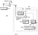
Фиг. 2 - блок-схему системы связи, включающей в себя приемник. FIG. 2 is a block diagram of a communication system including a receiver.
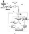
Фиг. 3 - блок-схему системы связи, включающей в себя приемник, согласно другому варианту изобретения. FIG. 3 is a block diagram of a communication system including a receiver according to another embodiment of the invention.
Лучший вариант осуществления изобретения
Как известно, настоящее изобретение реализует способ и устройство для определения уровня используемости принимаемого сигнала. Принимаемый сигнал содержит в себе сумму искомой (полезной) и избыточной (паразитной) частей. Обычно полезная часть содержит в себе первоначальный передаваемый сигнал, видоизмененный по амплитуде и фазе, а избыточная часть включает в себя шум и помехи. В настоящем изобретении приемник выделяет представление полезной составляющей из принимаемого сигнала и использует его для получения представления паразитной составляющей принимаемого сигнала. Затем приемник рассчитывает среднюю мощность, содержащуюся в каждой составляющей, и формирует отношение указанных двух мощностей. Указанное отношение, которое обычно называют как отношение несущей к помехам плюс шум, или С/(П+Ш), является критерием пригодности принимаемого сигнала.The best embodiment of the invention
As is known, the present invention implements a method and apparatus for determining the level of usability of a received signal. The received signal contains the sum of the desired (useful) and excess (spurious) parts. Usually the useful part contains the initial transmitted signal, modified in amplitude and phase, and the excess part includes noise and interference. In the present invention, the receiver extracts the representation of the useful component from the received signal and uses it to obtain a representation of the spurious component of the received signal. Then the receiver calculates the average power contained in each component, and forms the ratio of these two powers. This ratio, which is commonly referred to as the carrier to interference plus noise ratio, or C / (R + W), is a criterion for the suitability of the received signal.
Настоящее изобретение можно описать более полно со ссылкой на фиг. 1-3. Фиг. 1 иллюстрирует модель передаваемых информационных символов 100 и модель принимаемых измененных информационных символов 101. Иллюстрируемые на фиг.1 двухмерные модели символов являются типичными в цифровой передающей системе, использующей 16-разрядную квадратурную амплитудную модуляцию (КАМ), однако в технике обычно используют также модели символов, соответствующие альтернативным схемам цифровой модуляции типа квадратурной фазовой манипуляции (КФМ) и дифференциальной КФМ. The present invention can be described more fully with reference to FIG. 1-3. FIG. 1 illustrates a model of transmitted information symbols 100 and a model of received modified information symbols 101. The two-dimensional symbol models illustrated in FIG. 1 are typical in a digital transmission system using 16-bit quadrature amplitude modulation (QAM), however, symbol models are also commonly used in the technique. corresponding to alternative digital modulation schemes such as quadrature phase shift keying (CPM) and differential CPM.
В цифровой системе передачи передатчик излучает поток информационных символов, в котором каждый информационный символ представляет собой конкретное значение, выбранное из дискретного набора возможных значений, содержащихся в модели передаваемых информационных символов 100. Например, во время передачи конкретного символа передатчик может передавать информационный символ 103, показанный на модели передаваемых информационных символов 100. Передаваемый поток информационных символов распространяется от передатчика к приемнику по средству связи типа радиочастотного канала передачи. Поток информационных символов, принимаемый приемником, обычно изменен под влиянием нежелательных воздействий, встречающихся во время передачи по каналу передачи. In a digital transmission system, the transmitter emits an information symbol stream in which each information symbol represents a particular value selected from a discrete set of possible values contained in the model of transmitted information symbols 100. For example, during transmission of a particular symbol, the transmitter may transmit an information symbol 103 shown on the model of transmitted information symbols 100. The transmitted stream of information symbols propagates from the transmitter to the receiver by means of communication type radio frequency transmission channel. The stream of information symbols received by the receiver is usually changed under the influence of undesirable influences encountered during transmission over the transmission channel.
Передаваемый информационный символ 103 изменяется двумя способами. Во-первых, средство связи изменяет символ по амплитуде и фазе, фактически поворачивая и масштабируя модель передаваемых информационных символов 100 для производства модели принимаемых измененных информационных символов 101. Точная величина вращения и масштабирования, вносимая средством связи, обычно изменяется произвольным образом в функции времени вследствие эффекта Релеевского, или амплитудного замирания. Во-вторых, средство связи добавляет шум и помехи к передаваемому информационному символу 103, так что принимаемый информационный символ заменяется некоторой произвольной величиной. В многомерной системе связи, в которой используется географическое многократное использование ее средств, помехи возникают от использования средства связи другими передатчиками в системе. Шум появляется от различных источников типа теплового шума и шума окружающей среды. Систему связи, элементы которой размещены в нескольких местах, обычно конструируют таким образом, чтобы гарантировать, что вносимые каналом передачи шум и помехи остаются небольшими по сравнению с передаваемым информационным символом 103, таким образом, при нормальных условиях работы принимаемый информационный символ находится с большой вероятностью в области 102 около соответствующего ему передаваемого информационного символа. The transmitted information symbol 103 is changed in two ways. First, the communication medium changes the symbol in amplitude and phase, actually rotating and scaling the model of transmitted information symbols 100 to produce a model of the received modified information symbols 101. The exact value of rotation and scaling introduced by the communication medium usually changes arbitrarily in function of time due to the effect Rayleigh, or amplitude fading. Secondly, the communication medium adds noise and interference to the transmitted information symbol 103, so that the received information symbol is replaced by some arbitrary value. In a multidimensional communication system that uses geographic multiple use of its means, interference occurs from the use of the means of communication by other transmitters in the system. Noise comes from various sources such as thermal noise and environmental noise. A communication system, the elements of which are located in several places, is usually designed in such a way as to ensure that the noise and interference introduced by the transmission channel remain small compared to the transmitted information symbol 103, thus, under normal operating conditions, the received information symbol is likely to be area 102 near the corresponding transmitted information symbol.
В результате изменений, вносимых средствами связи, поток принимаемых информационных символов содержит в себе полезную и паразитную составляющие. Полезный сигнал, включающий в себя поток информационных символов, первоначально передаваемых передатчиком, представляет собой составляющую, которая вращается и масштабируется вследствие замирания. Паразитный сигнал представляет собой помехи и шум, добавляемые к потоку информационных символов средством связи. As a result of changes made by communication, the stream of received information symbols contains useful and spurious components. A useful signal, including a stream of information symbols originally transmitted by the transmitter, is a component that rotates and scales due to fading. The spurious signal is interference and noise added to the stream of information symbols by means of communication.
Фиг. 2 иллюстрирует систему связи 200, которая включает в себя передатчик 201, радиочастотный канал 202, приемник 203 и шум и помехи 204. Передатчик 201 может входить в состав центральной станции или аппарата (узла) связи типа приемопередающей радиостанции или радиотелефона. Подобно этому приемник 203 также может входить в состав аппарата связи или центральной станции. Как известно, узлы связи обеспечивают обмен информацией через радиочастотный канал 202 или средство связи с центральной станцией. Способ, которым осуществляется такая связь, известен и не подлежит комментарию в настоящей заявке. FIG. 2 illustrates a
Сигналы типа потока информационных символов передаются передатчиком 201 по радиочастотному каналу 202 или средству связи, где встречаются с шумом и помехами 204, и принимаются приемником 203. Принимаемые сигналы, которые включают в себя представление передаваемых сигналов, суммируемое с шумом и помехами 204, поступают в устройство 210 внутри приемника 203, которое содержит в себе схему определения (определитель) полезной составляющей 205, схему определения паразитной составляющей 206 и определитель пригодности сигнала 209. Определитель полезной составляющей 205 принимает сигналы и определяет из них нужную часть, В этом варианте осуществления изобретения полезная составляющая содержит оценку представления передаваемых символов и получается путем преобразования принимаемого сигнала из аналоговой в цифровую форму и применения обработки цифрового сигнала. Определитель паразитного сигнала 206 в действующем режиме подсоединен к определителю полезного сигнала 205 и принимает весь принимаемый сигнал и его полезную составляющую, в результате чего определяет паразитную составляющую (ненужную часть) принимаемых сигналов. Определитель 206 паразитного сигнала может содержать схему вычитания, которая вычитает полезную из принимаемых сигналов для определения паразитной составляющей. Определитель пригодности сигнала 209 принимает полезную и паразитную составляющие с блоков 205 и 206, соответственно, и на их основании определяет признаки пригодности принимаемых сигналов. Как кратко упоминалось выше, параметры пригодности главным образом включают в себя оценку отношения полезной составляющей к паразитной. Signals such as a stream of information symbols are transmitted by the
Устройство 210 может включать в себя схему усреднения (усреднитель) паразитной составляющей 207 и усреднитель полезной составляющей 208, которые принимают полезную и избыточную составляющие, соответственно, и получают из них соответствующие усредненные значения. Для определения параметра пригодности в определителе пригодности сигнала 209 используются средние значения, образованные усреднителем паразитной составляющей 207 и усреднителем полезной составляющей 208. Обычно средние значения, выработанные усреднителями 207 и 208, представляют собой средние интенсивности сигнала, определяемые путем усреднения возведенной в квадрат величины совокупности полезной и паразитной составляющих, соответственно; таким образом, параметры пригодности, обеспечиваемые определителем пригодности сигнала 209, приблизительно равняются вышеупомянутому отношению несущей к сумме помех и шума. Устройство 210 в приемнике 203 может представлять собой блок цифровой обработки сигналов (ЦОС), который включает в себя программы системы программного обеспечения, функционирующие как определители полезной и паразитной составляющих 205 и 206, усреднители паразитной и полезной составляющих 207 и 208 и определитель пригодности сигнала 209. The device 210 may include an averaging circuit (averager) of the
Фиг. 3 иллюстрирует систему связи 300, которая включает в себя передатчик 201, радиочастотный канал 202 и приемник 301. Передатчик 201 передает поток неизмененных информационных символов по радиочастотному каналу 202 к приемнику 301. В РЧ-канале 202 поток неизмененных информационных символов встречается с увеличивающимися эффектами замирания и дополнительными действиями шума и помех 204, дающими на входе приемника 301 поток измененных информационных символов. Например, каждый информационный символ потока неизменных информационных символов можно представить дискретным значением Д. Воздействия замирания в радиочастотном канале моделируются путем умножения каждого неизмененного информационного символа на сигнал замирания h, а действия шума и помех 204 представлены добавлением сигнала помех П к каждому подверженному замиранию информационному символу. При завершении их передачи по РЧ-каналу 202 составной поток информационных символов, поступающий на выход приемника, образует измененный поток информационных символов. Каждый символ измененного потока можно математически представить выражением Dh+П. Следовательно, каждый символ измененного потока содержит сумму полезной и паразитной составляющих, соответственно обозначенных Dh и П. FIG. 3 illustrates a
Приемник 301, включающий приемник сигнала 303, определитель символов 304, определитель сигнала замирания 305, определитель полезной составляющей 306, определитель паразитной составляющей 206 и определитель пригодности сигнала 209, используется для обработки измененного потока и обеспечения определения пригодности измененного потока. Измененный поток информационных символов поступает в приемник 301 через антенну и распространяется на вход приемника сигнала 303. Приемник сигнала 303 усиливает, фильтрует и преобразует измененный поток из аналоговой в цифровую форму. Цифровое представление измененного потока подается на входы определителя символов 304 и определителя сигнала замирания 305, где определяются представление каждого неизменного информационного символа D и представление сигнала замирания h, соответственно. Подробное рассмотрение способа определения представлений сигнала замирания и каждого неизменного информационного символа приведено в находящейся в процессе одновременного рассмотрения заявке на патент Соединенных Штатов с порядковым номером 07/783,289 под названием "Сигнал связи, имеющий составляющую контрольного сигнала временной области", принадлежащей фирме "Моторола, Инк". A
Представление каждого неизмененного информационного символа D и представление сигнала затухания h подаются в определитель полезной составляющей 306, где на основании этих двух входных представлений определяется полезная составляющая измененного потока. Например, определитель полезной составляющей 306 может быть цифровым умножителем, который обеспечивает выходной сигнал Dh. Определитель паразитной составляющей 206 принимает входные сигналы с определителя полезной составляющей 306 и приемника сигнала 303 и манипулирует ими для выделения паразитной составляющей измененного потока. The representation of each unchanged information symbol D and the representation of the attenuation signal h are supplied to the determinant of the
Как описывалось выше в связи с фиг. 2, определитель паразитной составляющей 206 может содержать схему вычитания, которая вычитает полезную составляющую Dh из каждого символа измененного потока Dh+П с целью нахождения паразитной составляющей Dh+П+Dh. Обеспеченные представления каждого неизменного информационного символа D и сигнала замирания h являются точными, паразитная составляющая приблизительно соответствует сигналу помехи П. Выходные сигналы определителя сигнала замирания 305 и определителя паразитной составляющей 206 поступают на определитель пригодности сигнала 209 для определения параметра пригодности измененного потока. Параметры пригодности определяются посредством оценки отношения представления сигнала замирания к паразитной составляющей, то есть h/П. As described above in connection with FIG. 2, the determinant of the
Приемник 301 может включать в себя также усреднитель паразитной составляющей 207 и усреднитель полезной составляющей 208, на которые поступают паразитная составляющая и представление сигнала замирания, соответственно, вырабатывающие усредненные значения соответственных входных сигналов. Произведенное усреднителем 208 полезной составляющей усреднение может включать в себя масштабирование усреднения сигнала замирания с помощью заранее установленного усреднения каждого информационного символа. Усредненные выходные сигналы усреднителя паразитной составляющей 207 и усреднителя 208 полезной составляющей поступают на определитель пригодности сигнала 209 для определения пригодности принимаемого сигнала. Как описывалось выше со ссылкой на фиг. 2, производимые усреднителями 208 полезной и 207 паразитной составляющих усреднения обычно представляют средние значения интенсивности сигналов; таким образом, параметры пригодности, обеспечиваемые определителем пригодности сигнала 209, соответствуют примерно отношению несущей к сумме помех и шума. При таком способе признаки пригодности сигнала (С/(П+Ш)) можно определять в течение пяти секунд. The
Настоящее изобретение раскрывает способ и устройство для определения признака пригодности принимаемого сигнала. С помощью настоящего изобретения приемник в системе связи с многократным использованием частоты, размещенной во множестве позиций, может быстро и точно проводить оценку пригодности принимаемого сигнала, что является важной для реализации системой функций, таких как назначение и перераспределение канала связи. Соответствующий настоящему изобретению способ обеспечивает значительно лучшую индикацию пригодности принимаемого сигнала по сравнению с измерением интенсивности принимаемого сигнала, поскольку он обеспечивает различение полезной и паразитной составляющих принимаемого сигнала, тогда как при измерении интенсивности принимаемого сигнала такое различение не производится. Кроме того, соответствующий настоящему изобретению способ обеспечивает более быструю, но в равной степени точную индикацию пригодности принимаемого сигнала по сравнению с измерением частоты появления ошибок в битах, особенно в географических областях с низкими частотами появления ошибок, что приводит к улучшенной работе системы связи, размещенной во множестве мест. The present invention discloses a method and apparatus for determining a suitability of a received signal. Using the present invention, a receiver in a multiple-frequency frequency communication system located in a plurality of positions can quickly and accurately evaluate the suitability of a received signal, which is important for the system to implement functions such as assigning and reallocating a communication channel. The method of the present invention provides a significantly better indication of the suitability of the received signal compared to measuring the intensity of the received signal, because it provides a distinction between the useful and spurious components of the received signal, while when measuring the intensity of the received signal, this is not distinguished. In addition, the method of the present invention provides a faster, but equally accurate indication of the suitability of the received signal compared to measuring the frequency of occurrence of errors in bits, especially in geographic areas with low frequencies of occurrence of errors, which leads to improved operation of the communication system located in many places.
Claims (7)
Applications Claiming Priority (2)
| Application Number | Priority Date | Filing Date | Title |
|---|---|---|---|
| US08/069,927 | 1993-05-28 | ||
| US08/069,927 US5440582A (en) | 1993-05-28 | 1993-05-28 | Method and apparatus for determining signal usability |
Publications (2)
| Publication Number | Publication Date |
|---|---|
| RU95122757A RU95122757A (en) | 1998-02-20 |
| RU2154342C2 true RU2154342C2 (en) | 2000-08-10 |
Family
ID=22092076
Family Applications (1)
| Application Number | Title | Priority Date | Filing Date |
|---|---|---|---|
| RU95122757/09A RU2154342C2 (en) | 1993-05-28 | 1994-05-11 | Method and device to determine fitness of signals received in communication system |
Country Status (18)
| Country | Link |
|---|---|
| US (1) | US5440582A (en) |
| EP (1) | EP0701752B1 (en) |
| JP (2) | JP3749730B2 (en) |
| CN (1) | CN1051416C (en) |
| AT (1) | ATE183038T1 (en) |
| AU (1) | AU674420B2 (en) |
| BR (1) | BR9406692A (en) |
| CA (1) | CA2161118C (en) |
| DE (1) | DE69419918T2 (en) |
| DK (1) | DK0701752T3 (en) |
| ES (1) | ES2136197T3 (en) |
| FI (1) | FI112563B (en) |
| GR (1) | GR3031425T3 (en) |
| MY (1) | MY110982A (en) |
| OA (1) | OA10245A (en) |
| PL (1) | PL173935B1 (en) |
| RU (1) | RU2154342C2 (en) |
| WO (1) | WO1994028637A1 (en) |
Families Citing this family (27)
| Publication number | Priority date | Publication date | Assignee | Title |
|---|---|---|---|---|
| US5406588A (en) * | 1993-05-28 | 1995-04-11 | Motorola, Inc. | Method and apparatus for mitigating distortion effects in the determination of signal usability |
| FR2713855B1 (en) * | 1993-12-15 | 1996-01-19 | Alcatel Telspace | Method for detecting a carrier recovery dropout and for determining the EB / NO ratio of a digital transmission link and device implementing this method. |
| JP2908217B2 (en) * | 1993-12-28 | 1999-06-21 | 日本電気株式会社 | Receive electric field level detection circuit |
| US5912932A (en) * | 1995-04-24 | 1999-06-15 | Lucent Technologies Inc. | Apparatus and methods for decoding a communication signal |
| US5867539A (en) * | 1995-07-21 | 1999-02-02 | Hitachi America, Ltd. | Methods and apparatus for reducing the effect of impulse noise on receivers |
| US5715240A (en) * | 1996-05-03 | 1998-02-03 | Motorola, Inc. | Communication device capable of estimating signal quality without synchronization pattern |
| US5812600A (en) * | 1996-07-26 | 1998-09-22 | Motorola, Inc. | Method and apparatus for mitigating distortion effects in the determination of signal usability |
| US5898730A (en) * | 1996-12-20 | 1999-04-27 | Motorola, Inc. | Method for determining signal quality of a communication channel |
| US5884215A (en) * | 1997-01-31 | 1999-03-16 | Motorola, Inc. | Method and apparatus for covariance matrix estimation in a weighted least-squares location solution |
| US5911124A (en) * | 1997-02-03 | 1999-06-08 | Motorola, Inc. | Method and apparatus for applying echo mitigation in a communication device |
| JP2885772B1 (en) * | 1997-12-17 | 1999-04-26 | 日本電気移動通信株式会社 | Reception method, reception quality estimation method, transmission power control method, and transmission / reception apparatus in CDMA system |
| US6229847B1 (en) | 1997-12-24 | 2001-05-08 | The United States Of America As Represented By The Secretary Of The Navy | Signal quality measurement device |
| FI112739B (en) * | 1998-05-25 | 2003-12-31 | Nokia Corp | Method and apparatus for detecting an interfering signal in a radio receiver |
| EP1108297B1 (en) * | 1998-08-28 | 2003-07-02 | Siemens Aktiengesellschaft | Method and device for measuring the transmission quality of a transmission channel |
| US7076264B2 (en) * | 1999-02-19 | 2006-07-11 | Qualcomm, Inc. | Power control in a cellular system using ES/IO and NT/I0 values |
| US6661832B1 (en) * | 1999-05-11 | 2003-12-09 | Qualcomm Incorporated | System and method for providing an accurate estimation of received signal interference for use in wireless communications systems |
| FR2796227B1 (en) * | 1999-07-08 | 2007-05-04 | Cit Alcatel | METHOD OF ESTIMATING THE NOISE SIGNAL RATIO IN A TELECOMMUNICATIONS RECEIVER AND APPLYING SAID METHOD TO CONTROLLING AN EMITTER |
| EP1089481B1 (en) * | 1999-09-17 | 2012-02-22 | TELEFONAKTIEBOLAGET LM ERICSSON (publ) | Method and apparatus for estimating residual noise in a signal and mobile telephone utilizing this method |
| US20010033622A1 (en) * | 2000-03-14 | 2001-10-25 | Joengren George | Robust utilization of feedback information in space-time coding |
| US6990137B2 (en) * | 2001-05-17 | 2006-01-24 | Qualcomm, Incorporated | System and method for received signal prediction in wireless communications systems |
| US7170924B2 (en) * | 2001-05-17 | 2007-01-30 | Qualcomm, Inc. | System and method for adjusting combiner weights using an adaptive algorithm in wireless communications system |
| US7076001B2 (en) * | 2001-10-16 | 2006-07-11 | Harris Corporation | System and method for an in-service decision-directed signal to noise ratio estimator |
| US7738848B2 (en) | 2003-01-14 | 2010-06-15 | Interdigital Technology Corporation | Received signal to noise indicator |
| US20040235423A1 (en) * | 2003-01-14 | 2004-11-25 | Interdigital Technology Corporation | Method and apparatus for network management using perceived signal to noise and interference indicator |
| EP2189978A1 (en) | 2004-08-30 | 2010-05-26 | QUALCOMM Incorporated | Adaptive De-Jitter Buffer for voice over IP |
| ATE527553T1 (en) * | 2006-02-28 | 2011-10-15 | Nokia Corp | METHOD AND DEVICE FOR NAVIGATION SYSTEMS |
| JP5082335B2 (en) * | 2006-08-21 | 2012-11-28 | 富士通株式会社 | Electronic board and backboard transmission method |
Family Cites Families (6)
| Publication number | Priority date | Publication date | Assignee | Title |
|---|---|---|---|---|
| US4408322A (en) * | 1980-11-07 | 1983-10-04 | Satellite Business Systems | Method and apparatus for measuring signal to noise ratio in a TDMA communications system |
| EP0233679B1 (en) * | 1986-01-18 | 1990-11-07 | Hewlett-Packard Limited | Non intrusive channel impairment analyser |
| DE3886107T2 (en) * | 1987-06-23 | 1994-05-26 | Nec Corp | Carrier / noise detector for digital transmission systems. |
| JPH0626343B2 (en) * | 1988-12-16 | 1994-04-06 | 日本電気株式会社 | Modulator / demodulator data transmission rate automatic switching system |
| US5170413A (en) * | 1990-12-24 | 1992-12-08 | Motorola, Inc. | Control strategy for reuse system assignments and handoff |
| US5323421A (en) * | 1992-09-30 | 1994-06-21 | Motorola, Inc. | Method and apparatus of estimating channel quality in a receiver |
-
1993
- 1993-05-28 US US08/069,927 patent/US5440582A/en not_active Expired - Lifetime
-
1994
- 1994-05-11 JP JP50068195A patent/JP3749730B2/en not_active Expired - Lifetime
- 1994-05-11 ES ES94917337T patent/ES2136197T3/en not_active Expired - Lifetime
- 1994-05-11 EP EP94917337A patent/EP0701752B1/en not_active Expired - Lifetime
- 1994-05-11 PL PL94311764A patent/PL173935B1/en not_active IP Right Cessation
- 1994-05-11 CN CN94192268A patent/CN1051416C/en not_active Expired - Lifetime
- 1994-05-11 AT AT94917337T patent/ATE183038T1/en not_active IP Right Cessation
- 1994-05-11 DE DE69419918T patent/DE69419918T2/en not_active Expired - Lifetime
- 1994-05-11 CA CA002161118A patent/CA2161118C/en not_active Expired - Lifetime
- 1994-05-11 DK DK94917337T patent/DK0701752T3/en active
- 1994-05-11 WO PCT/US1994/005154 patent/WO1994028637A1/en active IP Right Grant
- 1994-05-11 BR BR9406692A patent/BR9406692A/en not_active IP Right Cessation
- 1994-05-11 RU RU95122757/09A patent/RU2154342C2/en active
- 1994-05-11 AU AU69090/94A patent/AU674420B2/en not_active Expired
- 1994-05-17 MY MYPI94001257A patent/MY110982A/en unknown
-
1995
- 1995-11-08 FI FI955363A patent/FI112563B/en not_active IP Right Cessation
- 1995-11-28 OA OA60747A patent/OA10245A/en unknown
-
1999
- 1999-10-07 GR GR990402514T patent/GR3031425T3/en unknown
-
2005
- 2005-10-05 JP JP2005292916A patent/JP2006050672A/en active Pending
Non-Patent Citations (1)
| Title |
|---|
| ЧИСТЯКОВ П.И. и др. Радиоприемные устройства. - М.: Связьиздат, 1959, с. 592 - 594. БУГА Н.Н. и др. Радиоприемные устройства. - М.: Радио и связь, 1986, с. 31 - 32, 222 - 224. Каналы передачи данных/ Под ред. ШВАРЦМАНА В.О. - М.: Связь, 1970, с. 22 - 31. Помехозащищенность радиосистем со сложными сигналами /Под ред. ТУЗОВА Г.И. - М.: Радио и связь, 1985, с. 15 - 18. * |
Also Published As
| Publication number | Publication date |
|---|---|
| JPH08510881A (en) | 1996-11-12 |
| JP2006050672A (en) | 2006-02-16 |
| ATE183038T1 (en) | 1999-08-15 |
| AU674420B2 (en) | 1996-12-19 |
| EP0701752B1 (en) | 1999-08-04 |
| WO1994028637A1 (en) | 1994-12-08 |
| PL311764A1 (en) | 1996-03-18 |
| ES2136197T3 (en) | 1999-11-16 |
| DE69419918T2 (en) | 2000-03-16 |
| FI112563B (en) | 2003-12-15 |
| OA10245A (en) | 1997-10-07 |
| AU6909094A (en) | 1994-12-20 |
| BR9406692A (en) | 1996-01-30 |
| PL173935B1 (en) | 1998-05-29 |
| MY110982A (en) | 1999-07-31 |
| CA2161118C (en) | 1999-12-28 |
| EP0701752A1 (en) | 1996-03-20 |
| US5440582A (en) | 1995-08-08 |
| DK0701752T3 (en) | 2000-03-13 |
| JP3749730B2 (en) | 2006-03-01 |
| CN1124547A (en) | 1996-06-12 |
| FI955363A0 (en) | 1995-11-08 |
| EP0701752A4 (en) | 1997-10-01 |
| GR3031425T3 (en) | 2000-01-31 |
| CN1051416C (en) | 2000-04-12 |
| FI955363A (en) | 1995-11-08 |
| DE69419918D1 (en) | 1999-09-09 |
Similar Documents
| Publication | Publication Date | Title |
|---|---|---|
| RU2154342C2 (en) | Method and device to determine fitness of signals received in communication system | |
| JP4260900B2 (en) | Forward link power control in cellular systems using N ▲ down T ▼ / I ▲ down O ▼ values | |
| US6167275A (en) | Method and apparatus for determining a location of a communication unit in a wireless communication system | |
| TW480846B (en) | Method and apparatus for monitoring transmission quality | |
| US5170413A (en) | Control strategy for reuse system assignments and handoff | |
| US5469465A (en) | Method and apparatus for mitigating distortion effects in the determination of signal usability | |
| JPH06508254A (en) | Method and apparatus for adjusting power control thresholds in communication systems | |
| KR100415359B1 (en) | Method and apparatus for mitigation distorting effects in the determination of signal usability | |
| JP3439396B2 (en) | Electromagnetic environment design method and recording medium storing design program | |
| US6856793B2 (en) | Method and apparatus for measuring output power of devices for mobile communications | |
| JP3515457B2 (en) | Base station arrangement design method for wireless communication system | |
| Schonhoff et al. | Receiver structures for signals with unknown frequency and time-of-arrival | |
| JP2712853B2 (en) | Empty channel detection method | |
| JPS5880950A (en) | Monitoring system for circuit quality | |
| MXPA99009566A (en) | Forward link power control in a cellular system using nt |
Legal Events
| Date | Code | Title | Description |
|---|---|---|---|
| PC41 | Official registration of the transfer of exclusive right |
Effective date: 20120626 |