RU2148729C1 - Positive-displacement pump for handling viscous materials for use in manufacture of pneumatic tyres - Google Patents
Positive-displacement pump for handling viscous materials for use in manufacture of pneumatic tyres Download PDFInfo
- Publication number
- RU2148729C1 RU2148729C1 RU95110778/06A RU95110778A RU2148729C1 RU 2148729 C1 RU2148729 C1 RU 2148729C1 RU 95110778/06 A RU95110778/06 A RU 95110778/06A RU 95110778 A RU95110778 A RU 95110778A RU 2148729 C1 RU2148729 C1 RU 2148729C1
- Authority
- RU
- Russia
- Prior art keywords
- distributor
- pump
- pistons
- pump according
- outlet
- Prior art date
Links
Images
Classifications
-
- F—MECHANICAL ENGINEERING; LIGHTING; HEATING; WEAPONS; BLASTING
- F04—POSITIVE - DISPLACEMENT MACHINES FOR LIQUIDS; PUMPS FOR LIQUIDS OR ELASTIC FLUIDS
- F04B—POSITIVE-DISPLACEMENT MACHINES FOR LIQUIDS; PUMPS
- F04B15/00—Pumps adapted to handle specific fluids, e.g. by selection of specific materials for pumps or pump parts
- F04B15/02—Pumps adapted to handle specific fluids, e.g. by selection of specific materials for pumps or pump parts the fluids being viscous or non-homogeneous
-
- F—MECHANICAL ENGINEERING; LIGHTING; HEATING; WEAPONS; BLASTING
- F04—POSITIVE - DISPLACEMENT MACHINES FOR LIQUIDS; PUMPS FOR LIQUIDS OR ELASTIC FLUIDS
- F04B—POSITIVE-DISPLACEMENT MACHINES FOR LIQUIDS; PUMPS
- F04B25/00—Multi-stage pumps
- F04B25/04—Multi-stage pumps having cylinders coaxial with, or parallel or inclined to, main shaft axis
-
- B—PERFORMING OPERATIONS; TRANSPORTING
- B29—WORKING OF PLASTICS; WORKING OF SUBSTANCES IN A PLASTIC STATE IN GENERAL
- B29C—SHAPING OR JOINING OF PLASTICS; SHAPING OF MATERIAL IN A PLASTIC STATE, NOT OTHERWISE PROVIDED FOR; AFTER-TREATMENT OF THE SHAPED PRODUCTS, e.g. REPAIRING
- B29C48/00—Extrusion moulding, i.e. expressing the moulding material through a die or nozzle which imparts the desired form; Apparatus therefor
- B29C48/03—Extrusion moulding, i.e. expressing the moulding material through a die or nozzle which imparts the desired form; Apparatus therefor characterised by the shape of the extruded material at extrusion
- B29C48/07—Flat, e.g. panels
- B29C48/08—Flat, e.g. panels flexible, e.g. films
-
- B—PERFORMING OPERATIONS; TRANSPORTING
- B29—WORKING OF PLASTICS; WORKING OF SUBSTANCES IN A PLASTIC STATE IN GENERAL
- B29C—SHAPING OR JOINING OF PLASTICS; SHAPING OF MATERIAL IN A PLASTIC STATE, NOT OTHERWISE PROVIDED FOR; AFTER-TREATMENT OF THE SHAPED PRODUCTS, e.g. REPAIRING
- B29C48/00—Extrusion moulding, i.e. expressing the moulding material through a die or nozzle which imparts the desired form; Apparatus therefor
- B29C48/03—Extrusion moulding, i.e. expressing the moulding material through a die or nozzle which imparts the desired form; Apparatus therefor characterised by the shape of the extruded material at extrusion
- B29C48/09—Articles with cross-sections having partially or fully enclosed cavities, e.g. pipes or channels
- B29C48/10—Articles with cross-sections having partially or fully enclosed cavities, e.g. pipes or channels flexible, e.g. blown foils
-
- B—PERFORMING OPERATIONS; TRANSPORTING
- B29—WORKING OF PLASTICS; WORKING OF SUBSTANCES IN A PLASTIC STATE IN GENERAL
- B29C—SHAPING OR JOINING OF PLASTICS; SHAPING OF MATERIAL IN A PLASTIC STATE, NOT OTHERWISE PROVIDED FOR; AFTER-TREATMENT OF THE SHAPED PRODUCTS, e.g. REPAIRING
- B29C48/00—Extrusion moulding, i.e. expressing the moulding material through a die or nozzle which imparts the desired form; Apparatus therefor
- B29C48/25—Component parts, details or accessories; Auxiliary operations
- B29C48/30—Extrusion nozzles or dies
- B29C48/32—Extrusion nozzles or dies with annular openings, e.g. for forming tubular articles
- B29C48/33—Extrusion nozzles or dies with annular openings, e.g. for forming tubular articles with parts rotatable relative to each other
-
- B—PERFORMING OPERATIONS; TRANSPORTING
- B29—WORKING OF PLASTICS; WORKING OF SUBSTANCES IN A PLASTIC STATE IN GENERAL
- B29C—SHAPING OR JOINING OF PLASTICS; SHAPING OF MATERIAL IN A PLASTIC STATE, NOT OTHERWISE PROVIDED FOR; AFTER-TREATMENT OF THE SHAPED PRODUCTS, e.g. REPAIRING
- B29C48/00—Extrusion moulding, i.e. expressing the moulding material through a die or nozzle which imparts the desired form; Apparatus therefor
- B29C48/25—Component parts, details or accessories; Auxiliary operations
- B29C48/36—Means for plasticising or homogenising the moulding material or forcing it through the nozzle or die
- B29C48/375—Plasticisers, homogenisers or feeders comprising two or more stages
- B29C48/388—Plasticisers, homogenisers or feeders comprising two or more stages using a screw extruder and a ram or piston
-
- B—PERFORMING OPERATIONS; TRANSPORTING
- B29—WORKING OF PLASTICS; WORKING OF SUBSTANCES IN A PLASTIC STATE IN GENERAL
- B29C—SHAPING OR JOINING OF PLASTICS; SHAPING OF MATERIAL IN A PLASTIC STATE, NOT OTHERWISE PROVIDED FOR; AFTER-TREATMENT OF THE SHAPED PRODUCTS, e.g. REPAIRING
- B29C48/00—Extrusion moulding, i.e. expressing the moulding material through a die or nozzle which imparts the desired form; Apparatus therefor
- B29C48/25—Component parts, details or accessories; Auxiliary operations
- B29C48/36—Means for plasticising or homogenising the moulding material or forcing it through the nozzle or die
- B29C48/475—Means for plasticising or homogenising the moulding material or forcing it through the nozzle or die using pistons, accumulators or press rams
- B29C48/48—Two or more rams or pistons
-
- F—MECHANICAL ENGINEERING; LIGHTING; HEATING; WEAPONS; BLASTING
- F04—POSITIVE - DISPLACEMENT MACHINES FOR LIQUIDS; PUMPS FOR LIQUIDS OR ELASTIC FLUIDS
- F04B—POSITIVE-DISPLACEMENT MACHINES FOR LIQUIDS; PUMPS
- F04B1/00—Multi-cylinder machines or pumps characterised by number or arrangement of cylinders
- F04B1/12—Multi-cylinder machines or pumps characterised by number or arrangement of cylinders having cylinder axes coaxial with, or parallel or inclined to, main shaft axis
- F04B1/14—Multi-cylinder machines or pumps characterised by number or arrangement of cylinders having cylinder axes coaxial with, or parallel or inclined to, main shaft axis having stationary cylinders
- F04B1/18—Multi-cylinder machines or pumps characterised by number or arrangement of cylinders having cylinder axes coaxial with, or parallel or inclined to, main shaft axis having stationary cylinders having self-acting distribution members, i.e. actuated by working fluid
- F04B1/184—Cylindrical distribution members
-
- F—MECHANICAL ENGINEERING; LIGHTING; HEATING; WEAPONS; BLASTING
- F04—POSITIVE - DISPLACEMENT MACHINES FOR LIQUIDS; PUMPS FOR LIQUIDS OR ELASTIC FLUIDS
- F04B—POSITIVE-DISPLACEMENT MACHINES FOR LIQUIDS; PUMPS
- F04B27/00—Multi-cylinder pumps specially adapted for elastic fluids and characterised by number or arrangement of cylinders
- F04B27/04—Multi-cylinder pumps specially adapted for elastic fluids and characterised by number or arrangement of cylinders having cylinders in star- or fan-arrangement
- F04B27/067—Control
- F04B27/073—Control by varying the relative eccentricity between two members, e.g. a cam and a drive shaft
-
- F—MECHANICAL ENGINEERING; LIGHTING; HEATING; WEAPONS; BLASTING
- F04—POSITIVE - DISPLACEMENT MACHINES FOR LIQUIDS; PUMPS FOR LIQUIDS OR ELASTIC FLUIDS
- F04B—POSITIVE-DISPLACEMENT MACHINES FOR LIQUIDS; PUMPS
- F04B7/00—Piston machines or pumps characterised by having positively-driven valving
- F04B7/0019—Piston machines or pumps characterised by having positively-driven valving a common distribution member forming a single discharge distributor for a plurality of pumping chambers
- F04B7/0023—Piston machines or pumps characterised by having positively-driven valving a common distribution member forming a single discharge distributor for a plurality of pumping chambers and having a rotating movement
-
- B—PERFORMING OPERATIONS; TRANSPORTING
- B29—WORKING OF PLASTICS; WORKING OF SUBSTANCES IN A PLASTIC STATE IN GENERAL
- B29C—SHAPING OR JOINING OF PLASTICS; SHAPING OF MATERIAL IN A PLASTIC STATE, NOT OTHERWISE PROVIDED FOR; AFTER-TREATMENT OF THE SHAPED PRODUCTS, e.g. REPAIRING
- B29C48/00—Extrusion moulding, i.e. expressing the moulding material through a die or nozzle which imparts the desired form; Apparatus therefor
- B29C48/03—Extrusion moulding, i.e. expressing the moulding material through a die or nozzle which imparts the desired form; Apparatus therefor characterised by the shape of the extruded material at extrusion
-
- Y—GENERAL TAGGING OF NEW TECHNOLOGICAL DEVELOPMENTS; GENERAL TAGGING OF CROSS-SECTIONAL TECHNOLOGIES SPANNING OVER SEVERAL SECTIONS OF THE IPC; TECHNICAL SUBJECTS COVERED BY FORMER USPC CROSS-REFERENCE ART COLLECTIONS [XRACs] AND DIGESTS
- Y10—TECHNICAL SUBJECTS COVERED BY FORMER USPC
- Y10S—TECHNICAL SUBJECTS COVERED BY FORMER USPC CROSS-REFERENCE ART COLLECTIONS [XRACs] AND DIGESTS
- Y10S417/00—Pumps
- Y10S417/90—Slurry pumps, e.g. concrete
Abstract
Description
Настоящее изобретение относится к объемному насосу для перекачивания очень вязких материалов, таких как невулканизированная резина, и к способу производства пневматических шин с использованием такого насоса. The present invention relates to a volumetric pump for pumping very viscous materials, such as unvulcanized rubber, and to a method for manufacturing pneumatic tires using such a pump.
При производстве резиновых изделий требуется выдавливать продукты, очень точно дозируя их количество. Среди многих возможных применений можно упомянуть подготовку смесей резины, которая требует точной дозировки различных базовых компонентов, или сборку такого конечного изделия, как пневматическая шина, когда на вращающуюся основу требуется выдавливать строго определенные количества смесей резины. In the manufacture of rubber products, it is required to squeeze the products, very accurately dosing their quantity. Among the many possible applications, it is possible to mention the preparation of rubber mixtures, which requires the exact dosage of various basic components, or the assembly of such an end product as a pneumatic tire, when it is necessary to squeeze out strictly defined amounts of rubber mixtures onto a rotating base.
В этом последнем случае задача становится более сложной в связи с тем, что в этом варианте применения выдавливание не является непрерывным, а производится по требованию в соответствии с циклом, период которого соответствует времени, необходимому для сборки каждого изготавливаемого изделия, например, каждой пневмомашины. Важно достичь совершенного контроля над выдавливаемыми количествами, включая фазы остановки и начала экструзии. In this latter case, the task becomes more complicated due to the fact that in this application, the extrusion is not continuous, but is performed on demand in accordance with a cycle, the period of which corresponds to the time required for the assembly of each manufactured product, for example, each pneumatic machine. It is important to achieve perfect control over the extruded quantities, including the phases of stopping and the start of extrusion.
С этой целью чаще всего обеспечивается, чтобы дебит выдавливаемого материала зависел только от параметра привода наноса, а именно, например, скорости вращения приводного вала и именно таким путем достигается то, что каждый момент дебит строго пропорционален скорости вращения приводного вала. Из патента США 5261795 уже известен объемный насос, имеющий в одном из своих вариантов два поршня и шарики, играющие роль обратного клапана, управляемые штоками и качающимся рычагом. Этот насос отвечает этим целям. For this purpose, it is most often ensured that the flow rate of the extruded material depends only on the sediment drive parameter, namely, for example, the rotation speed of the drive shaft, and this is the way in which each flow rate is strictly proportional to the rotation speed of the drive shaft. A volume pump is already known from US Pat. No. 5,261,795, having in one of its variants two pistons and balls acting as a check valve, controlled by rods and a swing arm. This pump meets these goals.
Цель настоящего изобретения - усовершенствовать такой насос, в частности, сделать его легче с неизменяемым дебитом при заданном режиме без какого-либо ущерба для его объемной точности. Другой целью изобретения является облегчение протекания нагнетаемого материала, так как формулы смеси резины, используемые в промышленности по производству шин, могут давать продукты с очень высокой вязкостью. The purpose of the present invention is to improve such a pump, in particular, to make it easier with an unchanged flow rate at a given mode without any damage to its volumetric accuracy. Another objective of the invention is to facilitate the flow of injection material, since the rubber compound formulas used in the tire industry can produce products with very high viscosity.
Изобретение предлагает объемный насос для вязкого материала, имеющий корпус, включающий питающее отверстие для ввода материала и насос и выпускное отверстие для вывода материала (вещества) из насоса, причем указанный насос включает по меньшей мере один нагнетательный поршень, перемещающийся в цилиндре между нижней мертвой точкой и верхней мертвой точкой, при этом фаза нагнетания происходит в течение хода между нижней мертвой точкой и верхней мертвой точкой, указанный насос имеет подводящие проходы и нагнетательные проходы, выходящие в цилиндр или цилиндры, при этом подводящие и нагнетательные проходы образованы в корпусе, в местах, отделенных друг от друга, каждый подводящий проход перекрыт нагнетательным поршнем во время его движения от нижней мертвой точки в направлении верхней мертвой точки, кроме того, насос включает средства, чтобы заполнить цилиндр или цилиндры материалом в фазе подвода, а также насос включает вращающийся орган-распределитель, снабженный полостью с постоянным сообщением с выпускным отверстием, причем указанная полость образована таким образом, что орган-распределитель посредством вращения сообщает полость цилиндра с выпускным отверстием в течение нагнетательной фазы соответствующего поршня и изолирует цилиндр от выпускного отверстия вне нагнетательной фазы. The invention provides a volumetric pump for a viscous material, having a housing including a feed opening for introducing material and a pump and an outlet for withdrawing material (substance) from the pump, said pump including at least one pressure piston moving in the cylinder between the bottom dead center and top dead center, while the pumping phase occurs during the stroke between the bottom dead center and top dead center, the pump has inlet passages and discharge passages leaving a cylinder or cylinders, wherein the inlet and outlet passages are formed in the housing, in places separated from each other, each inlet passage is blocked by the delivery piston as it moves from the bottom dead center towards the top dead center, in addition, the pump includes means to fill the cylinder or cylinders with material in the supply phase, and the pump includes a rotating distributor provided with a cavity with constant communication with the outlet, and the specified cavity is formed in such a way that the distributor body by rotation communicates the cylinder cavity with the outlet during the discharge phase of the corresponding piston and isolates the cylinder from the outlet outside the discharge phase.
Благодаря использованию вращающегося органа-распределителя, дебит, на который способен насос, весьма увеличился для данных габаритов насоса и при прочих равных условиях. Кроме того, по отношению к насосам, известным из уже упоминаемого патента США 521795, дополнительные поршни можно более легко разместить. Thanks to the use of a rotating distributor, the flow rate that the pump is capable of has greatly increased for the given dimensions of the pump and other things being equal. Furthermore, with respect to pumps known from the already mentioned US Pat. No. 5,217,995, additional pistons can be more easily accommodated.
Другой аспект изобретения состоит в том, что или поршни органа-распределителя насоса приводятся в действие механически и синхронно с помощью единственного механического приводного вала. Это, разумеется, не исключает, что существуют две кинематические цепи, приводящие в действие, во-первых, указанный или указанные поршни, а во-вторых, другой орган-распределитель. Однако, это означает, что эти две кинематические цепи соединяются наверху и они сами приводятся в движение единственным механическим приводным валом. Another aspect of the invention is that either the pistons of the distributor body of the pump are driven mechanically and synchronously using a single mechanical drive shaft. This, of course, does not exclude that there are two kinematic chains that drive, firstly, said or indicated pistons, and secondly, another distributing organ. However, this means that these two kinematic chains are connected at the top and they themselves are driven by a single mechanical drive shaft.
В очень выгодном варианте, используя два нагнетательных поршня, имеют количество материала, выбрасываемого выпускным отверстием, прямо пропорциональное общему углу разворота приводного вала. Следовательно, дебит насоса является в каждый момент функцией скорости вращения приводного вала. Даже используя насос с единственным поршнем, отвечающим характеристикам изобретения благодаря прямому и синхронному управлению поршнем и органом-распределителем; средний дебит, т.е. дебит, наблюдаемый в период времени больше одного цикла, является прямо пропорциональным скорости приводного вала. Насос, согласно изобретению, позволяет получать данный дебит путем выбора скорости приведения в движение, адекватной для приводного вала. Это дебит является, таким образом, совершенно воспроизводимым, по крайней мере, для данного материала. In a very favorable embodiment, using two pressure pistons, they have the amount of material ejected by the outlet, which is directly proportional to the total angle of rotation of the drive shaft. Therefore, the pump rate is at every moment a function of the speed of rotation of the drive shaft. Even using a pump with a single piston that meets the characteristics of the invention thanks to the direct and synchronous control of the piston and the distributor; average flow rate, i.e. the flow rate observed over a period of more than one cycle is directly proportional to the speed of the drive shaft. The pump, according to the invention, allows to obtain this flow rate by selecting the speed of propulsion, adequate for the drive shaft. This flow rate is thus perfectly reproducible, at least for this material.
С другой стороны, согласно изобретению, корпус включает опору, в которой вращается указанный орган-распределитель, причем этот орган и опора имеют подогнанные друг к другу поверхности вращения, а прорезь указанного органа-распределителя включает в себя проход, заканчивающийся на вращающейся поверхности указанного органа, и в которой рабочая часть включает столько же каналов, сколько цилиндров, причем каждый канал выходит с одной стороны в нагнетательный проход, а с другой стороны на вращательную поверхность опоры в точках, выстроенных в линию и распределенных равномерно на указанной поверхности опоры таким образом, что один и тот же проход (зазор) проходит последовательно перед каждым из этих каналов во время его вращательного движения, причем проход и каналы так образованы по отношению друг к другу, что орган-распределитель посредством вращения соединяет, сообщает цилиндр с выпускным отверстием в течение нагнетательной фазы соответствующего поршня и изолирует этот цилиндр от выпускного отверстия вне нагнетательных фаз. On the other hand, according to the invention, the housing includes a support in which the said distributing organ rotates, wherein this organ and the support have surfaces of rotation fitted to each other, and the slot of said distributing organ includes a passage ending on the rotating surface of the said organ, and in which the working part includes as many channels as there are cylinders, with each channel extending on the one hand into the discharge passage, and on the other hand on the rotational surface of the support at points built in a line and evenly distributed on the indicated surface of the support in such a way that the same passage (gap) passes sequentially in front of each of these channels during its rotational movement, and the passage and channels are so formed in relation to each other that the distributor means rotates, communicates with the cylinder the outlet during the injection phase of the corresponding piston and isolates this cylinder from the outlet outside the injection phases.
Чтобы лучше понять изобретение, описаны два конкретных примера осуществления этого изобретения, каждый со ссылкой на три фигуры:
фиг. 1 - разрез по АА фиг. 2;
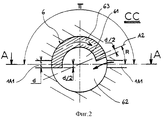
фиг. 2 - вид в разрезе по СС фиг. 1;
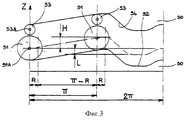
фиг. 3 - горизонтальная развертка кулачка, используемого в насосе, демонстрируемом на фиг. 1 и 2;
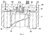
фиг. 4 - разрез по ВВ фиг. 5;
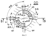
фиг. 5 - разрез по ДД фиг. 4;
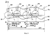
фиг. 6 показывает горизонтальную (плоскую) развертку кулачка, применяемого в насосе, демонстрируемом на фиг. 4 и 5;
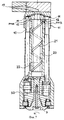
фиг. 7 - общий вид насоса.In order to better understand the invention, two specific embodiments of this invention are described, each with reference to three figures:
FIG. 1 is a section along AA of FIG. 2;
FIG. 2 is a cross-sectional view along the CC of FIG. 1;
FIG. 3 is a horizontal scan of a cam used in the pump shown in FIG. 1 and 2;
FIG. 4 is a section along BB of FIG. 5;
FIG. 5 is a section along the DD of FIG. 4;
FIG. 6 shows a horizontal (flat) scan of the cam used in the pump shown in FIG. 4 and 5;
FIG. 7 is a general view of the pump.
Для полного понимания изобретения читателю предлагается обратиться к патенту US 5261795, описание которого включено сюда как ссылка, справочный материал. Первый вариант изобретения иллюстрируется на фиг. 1 - 3. Второй вариант изобретения описан на фиг. 4 - 6. Фиг. 7 показывает общее устройство насоса и позволяет хорошо понять отличительные признаки, характерные для двух вариантов. For a complete understanding of the invention, the reader is invited to refer to patent US 5261795, the description of which is incorporated herein by reference, reference material. A first embodiment of the invention is illustrated in FIG. 1 to 3. A second embodiment of the invention is described in FIG. 4-6. FIG. 7 shows the general arrangement of the pump and allows a good understanding of the distinguishing features of the two options.
Первый вариант показывает насос с двумя нагнетательными поршнями 10, движение которых между нижней мертвой точкой и верхней мертвой точкой идет в направлении, параллельном оси Z насоса. Фиг. 1 (так же, как и фиг. 4) показывает разрез по плоскости, содержащей ось Z насоса. Можно увидеть корпус 1 насоса, включающий (см. фиг. 7) питающее отверстие 22, а также выпускное отверстие 17, устроенное соответствующим образом, имеющее, например, форму щели. Поршни 10 расположены в корпусе насоса аксиально. The first embodiment shows a pump with two
На фиг. 1 можно увидеть поршни, каждый передвигающийся в цилиндре 11, образованном в корпусе насоса. Следовательно, цилиндры 11 являются фиксированными, неподвижными относительно корпуса 1 насоса. Виден винт подкачивания 21, поворачивающийся в камере перемещения (перепуска) 20, которая является центральной и вокруг которой расположены указанные цилиндры 11, причем оси этих цилиндров параллельны оси Z насоса. Указанный винт 21 подкачивания применяется как механические средства, перемещение которых обеспечивает принудительное перемещение материала от питающего отверстия 22 к каждому из указанных цилиндров 11. Прорези 12 обеспечивают сообщение между камерой 20 перемещения и цилиндрами 11 и составляют таким образом подводящий проход, устроенный в корпусе насоса. In FIG. 1, pistons can be seen, each moving in a
В нескольких местах чертежей можно заметить такие стрелки, как стрелка, проведенная на уровне прорези 12 справа на фиг. 1. Эти стрелки символизируют поток материала и помогают понять функционирование насоса. At several points in the drawings, arrows such as an arrow drawn at the level of
Корпус 1 насоса включает промежуточную деталь 1A и крышку 1B, которые жестко соединены с корпусом при монтаже и могут рассматриваться, как функционально составляющие часть указанного корпуса. Промежуточная деталь 1A перекрывает цилиндры 11 со стороны нагнетания; в ней просверлены каналы 1A1 (столько же, сколько цилиндров, следовательно, здесь два), входящие каждый, с одной стороны, в цилиндр, а, с другой стороны, на поверхность опоры 1A2, расположенной концентрично оси насоса. Опора 1A2 поддерживает вращающийся орган-распределитель. Ось этого органа является, следовательно, параллельной направлению движения поршней. Вращающийся орган-распределитель и опора подогнаны с очень небольшим зазором. Они имеют формы вращения, адаптированные друг к другу. Опора 1A2 поддерживает также винт подкачивания 21, непосредственно соединенный с органом-распределителем. Это очень выгодно, так как можно избежать того, чтобы винт работал без опоры, делая тем самым ненужным предусматривать подшипник качения или специальный опорный подшипник. Таким образом сконструированный орган-распределитель включает, следовательно, функцию сбора перекачиваемого материала и функцию механической опоры (опоры), обеспечивая этим также весьма большую компактность насоса. The
Каждый из этих каналов составляет, таким образом, нагнетательный проход, устроенный в указанном корпусе, в месте, отделенном от места, где устроен проход подвода к тому же цилиндру. Указанные каналы 1A1 выходят на поверхность опоры 1A2 в точках, выстроенных по окружности и равномерно распределенных. Наконец крышка 1B имеет центральный канал 1B1 для подвода материала к выпускному отверстию 17. Each of these channels thus constitutes an injection passage arranged in said housing in a place separated from the place where the passage for supplying the same cylinder is arranged. These channels 1A1 go to the surface of the support 1A2 at points aligned in a circle and evenly distributed. Finally, the
Орган-распределитель выполнен в виде цилиндрического золотника 6, вращающегося в указанной опоре 1A2. Опора 1A2 и цилиндрический золотник являются здесь цилиндрическими. Этот цилиндрический золотник 6 имеет осевое отверстие 61, а также проход 62, имеющий форму щели, расположенной перпендикулярно указанному отверстию. Отверстие 61 и проход 62 составляют полость, через которую собранный материал проходит в направлении выпускного отверстия 17 насоса. The distributor is made in the form of a
Чтобы обеспечить дебит нагнетания, который может быть строго непрерывным (т. е. не пульсирующим), предпочтительно использовать, по меньшей мере, два поршня, устроенные так, чтобы их нагнетательные фазы следовали друг за другом, последовательно. В этом случае можно будет успешно использовать вращательный кулачок 50, обеспечивающий движение нагнетательных поршней, так, чтобы сумма нагнетаемых дебитов была пропорциональна скорости вращения кулачка 50. In order to ensure an injection rate that can be strictly continuous (i.e., not pulsating), it is preferable to use at least two pistons arranged so that their injection phases follow one after another, in series. In this case, it will be possible to successfully use the
В этом последнем случае удобство применения и точность насоса являются такими, что возможно даже выдавать количество материала, которое меньше единичного рабочего объема цилиндра, достигаемого одним из поршней. Таким образом, количество вытолкнутого материала является прямо пропорциональным углу, на который был довернут приводной вал, даже, если этот угол соответствует перемещению поршня меньше полезного хода, во время которого поршень эффективно нагнетает материал. Количество резины, нагнетаемой насосом, прямо пропорционально общему углу поворота его приводного вала. Другими словами, количество резины прямо пропорционально числу оборотов, производимых приводным валом, учитывая возможный неполный оборот. In this latter case, the ease of use and accuracy of the pump are such that it is even possible to produce an amount of material that is less than the unit working volume of the cylinder reached by one of the pistons. Thus, the amount of material ejected is directly proportional to the angle at which the drive shaft was rotated, even if this angle corresponds to the movement of the piston less than the effective stroke, during which the piston effectively pumps the material. The amount of rubber pumped by the pump is directly proportional to the total angle of rotation of its drive shaft. In other words, the amount of rubber is directly proportional to the number of revolutions produced by the drive shaft, given the possible incomplete revolution.
При применении изобретения для перекачки невулканизированных резин (сырье или вулканизируемые соединения) было установлено, что легко сделать винт подкачивания 21 обеспечивающим проталкивание материала так, что с помощью единственного механического вала 3 управляют не только одновременно движением поршней 10 и вращательного органа-распределителя (управления, которые должны быть, разумеется, синхронными), но также движением винта подкачивания 21. При очень простой реализации настоящего изобретения указанный винт для подкачки 21 поворачивается с той же скоростью, что и кулачок 50 и цилиндрический золотник 6. When applying the invention for pumping unvulcanized rubbers (raw materials or vulcanizable compounds), it was found that it is easy to make the pumping
Таким образом, предлагается интересный конструктивный вариант выполнения очень компактного насоса. Достаточно расположить винт для подкачивания 21 в продолжении непосредственно приводного вала 3, смонтировать кулачок 50 прямо на указанном приводном валу 3 и расположить цилиндрический золотник в прямом продолжении винта для подкачивания 21. Таким образом, винт для подкачивания 21 и цилиндрический золотник 6 образуют раздельные аксиально прилегающие зоны одного того же вращательного органа. Thus, an interesting constructive embodiment of a very compact pump is proposed. It is enough to place the screw for pumping 21 in the continuation directly of the
Для более полного понимания как удобно выполнить цилиндрический золотник 6 и организовать управление поршнями 10, достаточно более пристально изучить фиг. 2 и 3 одновременно с приведенными ниже объяснениями. For a more complete understanding of how convenient it is to make a
Фиг. 3 - диаграмма, представляющая ход вращательного движения ролика 51 для напора, толкания в направлении верхней мертвой точки, а также пути 54 вращательного движения ролика возврата 53 к нижней мертвой точке. Разумеется, один и тот же ролик смог бы одновременно обеспечить движение к верхней мертвой точке и движение к нижней мертвой точке. Оси вращения 51A и 53A роликов 51 и 53, наложенные друг на друга, на фиг. 3 жестко соединены с одним и тем же поршнем 10. Осевые движения (движения, параллельные оси Z) указанных осей вращения 51A и 53A торца 10A соответствующего поршня 10 являются идентичными: перемещению "Z" роликов 51 и 53 соответствует, следовательно, идентичное перемещение "Z" соответствующего поршня 10. Фиг. 3 показывает на оси ординат положение вдоль оси Z указанных осей вращения роликов, следовательно, положение соответствующего поршня 10 относительно угловой оси абсцисс показательное, характерное для углового положения кулачка 50. FIG. 3 is a diagram showing the rotational movement of the
На диаграмме фиг. 3 можно видеть полезный ход H поршня: это ход, который производится к верхней мертвой точке после того, как перекрыта соответствующая прорезь 12. На кулачке 50 можно выделить скос с постоянным уклоном, развернутый на π - R радиан. Величина угла R характеризует амплитуду перекрывания между работой по нагнетанию двумя поршнями, фазы нагнетания которых являются последовательными. In the diagram of FIG. 3 you can see the useful piston stroke H: this is the stroke that is made to the top dead center after the
Когда ролик 51 катится по указанному скосу с постоянным уклоном, поршень 10, который жестко с ним соединен, обеспечивает нагнетательный дебит так, что дебит прямо пропорционален скорости вращения кулачка 50 с участком сжимаемости материала, с которым он взаимодействует. When the
По обе стороны от этого скоса кулачок 50 имеет участки, называемые зонами R перекрытия, которые начинаются и заканчиваются на угловых позициях, отдельных от π радиан. Когда поршни сами диаметрально противоположны, группы роликов 51 и 53, каждый управляющие поршнем 10, сами отделены по угловому расположению от π радиан. Зоны R перекрытия образованы таким образом, что сумма нагнетаемых дебитов посредством двух поршней в течение их функционирования в перекрытии идентична дебиту, нагнетаемому единственным из поршней, когда его продвижение вперед регулируется скосом с постоянным уклоном. Существование перекрытия между поршнями и позволяет обеспечить точное, без толчков функционирование. On either side of this bevel, the
Во второй части кулачка 50 можно видеть участок, обеспечивающий возврат рассматриваемого поршня к его нижней мертвой точке, движение, в течение которого прорезь 12 открыта, затем первое продвижение вперед, ход L, чтобы перекрыть прорезь. In the second part of the
Плоскость разреза, в соответствии с которой образована фиг. 2, проходит через проход 62 цилиндрического золотника 6. В центре можно увидеть отверстие 61, через которое материал подается к выпускному отверстию 17 насоса. Плоскость разреза AA проходит через центры каналов 1A1. Угловое регулирование цилиндрического золотника 6 относительно кулачка 50 осуществляется так, что в самом начале фазы перекрытия золотник 6 откроет канал 1A1, соответствующий поршню 10, ролик 51 которого попадает на участок перекрытия, предшествующий скосу с постоянным уклоном. Речь идет о канале 1A1, расположенном слева на фиг. 2. Отметим, что стадия, достигнутая в рабочем цикле насоса, которая представлена на фиг. 2, не является точно такой, как стадия, показанная на фиг. 1. На этой фигуре поршень 10 справа еще не перекрыл прорезь 12, тогда как на фиг. 2 цилиндрический золотник 6 откроет соответствующий канал 1A1 (канал, расположенный на фиг. 2 слева), что может произойти только, если поршень 10 совершенно перекрыл прорезь 12, обеспечивая таким образом герметичность между камерой перепуска 20 и полостью цилиндра 11. The cut plane in accordance with which FIG. 2, passes through the
Чтобы закрыть другой канал 1A1 в нужный момент, следует рассчитать размеры экрана 63, образованного цилиндрическим золотником 6, с учетом выбранного перекрытия. С этой целью, по отношению к линии AA плоскости разреза рядом с каналом 1A1 справа на чертеже приведена амплитуда R. Фиг. 2 и 3 точно соответствуют той же самой стадии цикла функционирования. Зная, что линия плоскости разреза AA и осевая линия A2 определили бы границы указанного экрана, если каналы 1A1 имели размер, равный нулю в направлении по окружности, увеличивают размер экрана с обеих сторон в направлении по окружности на величину, пропорциональную реальному размеру "d" указанных каналов 1A1. Отметим еще, что линия AA проходит через среднюю точку каналов 1A1, видных в разрезе, показанном на фиг. 2. Экран 63, который образует цилиндрический золотник 6, выходит, следовательно, за дугу π - R на величину, заданную d/2, где d является разверткой в направлении по окружности указанных каналов 1A1. Поэтому, когда золотник (следовательно, кулачок 50) будет повернут на величину, соответствующую перекрытию R, канал 1A1, соответствующий поршню 10, прибывающему в верхнюю мертвую точку, будет перекрыт, что позволяет этому поршню снова отправиться к нижней мертвой точке, не всасывая материал. To close another channel 1A1 at the right time, it is necessary to calculate the dimensions of the
Заметим, что ничего не меняя ни в кулачке, ни в цилиндрическом золотнике, можно вставить два других поршня на равном удалении между двумя первыми. При условии подгонки винта для подкачивания, когда в случае необходимости нужно обеспечить полное заполнение цилиндров, можно таким образом удвоить номинальный дебит насоса при прочих равных условиях. Более обобщенно можно сказать, что возможно использовать любое парное число поршней и в случае необходимости приспосабливать соответственно винт для подкачивания и/или полезный рабочий объем цилиндра, достигаемый поршнями. Note that without changing anything in the cam or in the cylindrical spool, you can insert two other pistons at an equal distance between the first two. Provided that the pre-supply screw is adjusted, when it is necessary to ensure full filling of the cylinders, if necessary, it is possible to double the nominal flow rate of the pump, all other things being equal. More generally, it can be said that it is possible to use any pair of pistons and, if necessary, to adjust, respectively, a pumping screw and / or the effective working volume of the cylinder reached by the pistons.
Возможно также применять непарное число поршней, при условии подгонки кулачка 50, что для специалиста в свете приведенных выше объяснений не составит труда. It is also possible to use an unpaired number of pistons, provided that the
Второй вариант описан со ссылкой на фиг. 4 - 6. Он включает четыре поршня. Этот насос устроен так, что четное число поршней работает на нагнетание одновременно, причем они расположены напротив друг друга относительно оси насоса. В случае значительных нагрузок это позволяет хорошо уравновесить усилия, которым подвергается насос. A second embodiment is described with reference to FIG. 4 - 6. It includes four pistons. This pump is designed so that an even number of pistons works at the same time, and they are located opposite each other relative to the axis of the pump. In case of significant loads, this makes it possible to balance well the forces to which the pump is subjected.
В этом случае указанная полость или указанные полости расположены осесимметрично относительно оси вращения цилиндрического золотника 6, образуя вращательный распределитель. Кулачок 50, видимый на фиг. 6, разделен на две одинаковые половины, с разворотом каждой на дугу π радиан. Проходя вдоль каждой из этих половин, можно встретить последовательно первую зону R перекрытия, скос с постоянным уклоном, развернутый на (π /2) - R радиан. Как объяснено ранее, ход H - это полезный ход, в течение которого рассматриваемый поршень нагнетает материал в направлении выпускного отверстия 17. На кулачке 50 затем встречается вторая зона R перекрытия, образованная дополнительно к первой, затем участок возврата к нижней мертвой точке и, наконец, участок, вызывающий первое продвижение в направлении к верхней мертвой точке на величину L, вполне достаточную, чтобы обеспечить перекрытие прорезей 12. In this case, the specified cavity or these cavities are located axisymmetrically relative to the axis of rotation of the
Следуя принципу, идентичному тому, который был приведен в первом варианте, экраны 63 цилиндрического золотника 6, которые могут перекрывать и открывать каналы 1A1, рассчитываются по размерам в зависимости от степени желаемого перекрытия (определяемого углом R) и в зависимости от размера по окружности d указанных каналов 1A1. Following a principle identical to that given in the first embodiment, the
В более общем виде можно сказать, что возможно, следуя изложенным принципам, сконструировать насос, имеющий четное число поршней и больше или равное четырем. В частности, можно использовать с идентичным кулачком 50 число, кратное четырем поршням, распределенным на равновеликом расстоянии. In a more general form, we can say that it is possible, following the principles set forth, to construct a pump having an even number of pistons and greater than or equal to four. In particular, a multiple of four pistons distributed at an equal distance can be used with an
Чтобы заставить работать такой насос, можно легко присоединить его к источнику мощности, передающему вращающий момент на приводной вал 3. Например, корпус 1 насоса может легко быть схвачен роботом-манипулятором, передающим движение на приводной вал 3 и обеспечивающим все перемещения, которые желательны, в зависимости от выбранного применения. To make such a pump work, you can easily connect it to a power source that transmits torque to the
Изобретение относится также к способу производства пневматических шин, при котором необработанную заготовку постепенно собирают, откладывая на вращающуюся основу предварительно определенные компоненты в желаемое место, причем, по крайней мере, наложение некоторых из заранее определенных компонентов из резины производится подведением выпускного отверстия, по крайней мере, одного насоса, согласно изобретению, к указанной основе и сообщая указанному отверстию относительные движения, подходящие для указанной основы, в то время как основа приводится во вращение. The invention also relates to a method for manufacturing pneumatic tires, in which an untreated workpiece is gradually assembled, laying on a rotating base pre-defined components in a desired location, and at least some of the pre-defined components from rubber are superimposed by bringing an outlet at least one pump, according to the invention, to the specified basis and giving the specified hole relative motions suitable for the specified basis, while and is driven in rotation.
На основе изложенных принципов специалист не будет иметь никаких трудностей, чтобы приспособить насос к точному применению, которое он бы хотел получить. Точная форма органа-распределителя, а также устройство управления, регулирования движениями поршней и указанного органа-распределителя, разумеется, может иметь многочисленные варианты. Можно также закрывать проход для подвода к цилиндрам через цилиндрический золотник, который может образовывать одну деталь с цилиндрическим золотником, применяемым при нагнетании. Кроме того, поршни и цилиндры могут иметь форму, весьма отличную от той, которая была продемонстрирована. Можно было бы использовать поршень-плунжер, в этом случае термин "цилиндр" обозначал бы скорее камеру перекачки. Такой насос оказывается чрезвычайно прочным и точным. Он обеспечивает надежную работу при использовании для материалов таких трудных для перекачки, как резиновые вулканизированные соединения, такого вида, которые применяются при производстве пневматических шин. Based on the above principles, the specialist will not have any difficulties to adapt the pump to the exact application that he would like to receive. The exact shape of the distributor, as well as the control device for controlling the movements of the pistons and the said distributor, of course, can have numerous options. You can also close the passage for approaching the cylinders through a cylindrical spool, which can form one part with a cylindrical spool used for injection. In addition, the pistons and cylinders may have a very different shape from that which was demonstrated. A plunger piston could be used, in which case the term “cylinder” would more likely mean a transfer chamber. Such a pump is extremely durable and accurate. It provides reliable operation when used for materials as difficult to pump as rubber vulcanized compounds of the kind used in the manufacture of pneumatic tires.
Claims (25)
Applications Claiming Priority (2)
| Application Number | Priority Date | Filing Date | Title |
|---|---|---|---|
| FR9408303A FR2721662A1 (en) | 1994-06-28 | 1994-06-28 | Positive displacement pump. |
| FR9408303 | 1994-06-28 |
Publications (2)
| Publication Number | Publication Date |
|---|---|
| RU95110778A RU95110778A (en) | 1997-06-10 |
| RU2148729C1 true RU2148729C1 (en) | 2000-05-10 |
Family
ID=9465028
Family Applications (1)
| Application Number | Title | Priority Date | Filing Date |
|---|---|---|---|
| RU95110778/06A RU2148729C1 (en) | 1994-06-28 | 1995-06-27 | Positive-displacement pump for handling viscous materials for use in manufacture of pneumatic tyres |
Country Status (12)
| Country | Link |
|---|---|
| US (1) | US5655891A (en) |
| EP (1) | EP0690229B1 (en) |
| JP (1) | JPH0821354A (en) |
| KR (1) | KR100318358B1 (en) |
| CN (1) | CN1092290C (en) |
| AT (1) | ATE206504T1 (en) |
| BR (1) | BR9502954A (en) |
| CA (1) | CA2152145A1 (en) |
| DE (1) | DE69522999T2 (en) |
| FR (1) | FR2721662A1 (en) |
| RU (1) | RU2148729C1 (en) |
| TW (1) | TW291525B (en) |
Cited By (1)
| Publication number | Priority date | Publication date | Assignee | Title |
|---|---|---|---|---|
| RU2531391C2 (en) * | 2009-06-11 | 2014-10-20 | Манфред А.А. ЛУПКЕ | Extrusion tool for pipe extrusion |
Families Citing this family (16)
| Publication number | Priority date | Publication date | Assignee | Title |
|---|---|---|---|---|
| IT1280957B1 (en) * | 1995-10-06 | 1998-02-11 | Turbosol Produzione Spa | MACHINE FOR PUMPING MATERIALS FOR BUILDING |
| IT1294068B1 (en) * | 1997-01-17 | 1999-03-22 | Gianguido Ravellini | PUMPING DEVICE, IN PARTICULAR FOR CEMENTITIOUS MATERIAL. |
| JP3805929B2 (en) * | 1999-07-05 | 2006-08-09 | パイオニア株式会社 | Information recording apparatus and information recording method |
| JP2001073933A (en) | 1999-09-01 | 2001-03-21 | Bridgestone Corp | Positive-displacement extruding machine and extruding method for viscous material |
| WO2002026471A1 (en) * | 2000-09-28 | 2002-04-04 | Berstorff Gmbh | Screw extruder and gear pump arrangement for highly viscous media |
| FR2815287A1 (en) * | 2000-10-18 | 2002-04-19 | Sedepro | MANUFACTURE OF A STRIP BY EXTRUSION OF A TUBE THEN FLATTENING THE TUBE |
| JP2002160284A (en) | 2000-11-22 | 2002-06-04 | Bridgestone Corp | Method for extruding rubber material for tire and extrusion device |
| DE60312986T2 (en) | 2002-06-03 | 2007-12-13 | Société de Technologie Michelin | DEVICE FOR PRODUCING A REINFORCEMENT STRUCTURE FOR A TIRE WITH A THREADED TURNING MECHANISM |
| DE60312983T2 (en) | 2002-06-03 | 2007-12-13 | Société de Technologie Michelin | PREPARATION OF A TIRE REINFORCEMENT STRUCTURE WITH THE VOLUME CONTROL OF THE MATRIX |
| FR2944837B1 (en) * | 2009-04-24 | 2016-06-03 | Soc De Tech Michelin | VOLUMETRIC PUMP COMPRISING A PRESSURE ABSORBER |
| DE202009014863U1 (en) | 2009-12-16 | 2010-03-25 | Hsu, Jui-Lin, Chung Ho City | gauge |
| FR3067967A1 (en) | 2017-06-22 | 2018-12-28 | Compagnie Generale Des Etablissements Michelin | INSTALLATION AND COEXTRUSION METHOD |
| US11867162B2 (en) | 2018-10-14 | 2024-01-09 | Swissinnov Product Sarl | Precision, constant-flow reciprocating pump |
| US11506229B2 (en) | 2019-10-25 | 2022-11-22 | Tonand Inc. | Modular hydraulic device |
| US11333145B2 (en) * | 2019-10-25 | 2022-05-17 | Tonand Inc. | Cylinder on demand hydraulic device |
| FR3128897B1 (en) | 2021-11-09 | 2023-09-29 | Michelin & Cie | PNEUMATIC TIRE MANUFACTURING FACILITY PROVIDED WITH TOOL FOLLOWING COMPASSES |
Family Cites Families (13)
| Publication number | Priority date | Publication date | Assignee | Title |
|---|---|---|---|---|
| FR572925A (en) * | 1923-01-27 | 1924-06-16 | Suction and pressure pump with constant flow | |
| DE844535C (en) * | 1950-10-01 | 1952-07-21 | Helios App Wetzel & Schlosshau | Barrel pump |
| GB792081A (en) * | 1953-06-12 | 1958-03-19 | Autolifts And Engineering Comp | Improvements in or relating to swash-plate pumps |
| US3143076A (en) * | 1962-10-11 | 1964-08-04 | George L Pyritz | Constant pressure, variable volume delivery pump |
| US3327640A (en) * | 1965-01-13 | 1967-06-27 | Townsend Engineering Co | Pump for sausage mixture or the like |
| US3295451A (en) * | 1965-11-10 | 1967-01-03 | James E Smith | Hydraulic power converter |
| DE1653363A1 (en) * | 1966-04-09 | 1971-05-06 | Bosch Gmbh Robert | Reversible hydraulic machine |
| FR1522530A (en) * | 1967-03-17 | 1968-04-26 | Hydrostatic Balancing Pump | |
| DE3440850A1 (en) * | 1984-11-08 | 1986-05-22 | Mannesmann Rexroth GmbH, 8770 Lohr | AXIAL PISTON PUMP |
| US4756239A (en) * | 1986-11-28 | 1988-07-12 | Kabushiki Kaisha Toyoda Jidoshokki Seisakusho | Anti-rolling structure for double headed piston of disc cam type reciprocative compressor |
| FR2647852A1 (en) * | 1989-06-01 | 1990-12-07 | Michelin & Cie | VOLUMETRIC PUMP FOR PASTA MATERIAL |
| JP2995944B2 (en) * | 1991-09-13 | 1999-12-27 | 株式会社豊田自動織機製作所 | Piston reciprocating compressor |
| US5336052A (en) * | 1993-04-28 | 1994-08-09 | Abel Pumpen Gmbh & Co. Kg | Viscous material pump |
-
1994
- 1994-06-28 FR FR9408303A patent/FR2721662A1/en active Pending
-
1995
- 1995-06-02 EP EP95108512A patent/EP0690229B1/en not_active Expired - Lifetime
- 1995-06-02 AT AT95108512T patent/ATE206504T1/en not_active IP Right Cessation
- 1995-06-02 DE DE69522999T patent/DE69522999T2/en not_active Expired - Lifetime
- 1995-06-06 US US08/471,566 patent/US5655891A/en not_active Expired - Lifetime
- 1995-06-09 TW TW084105882A patent/TW291525B/zh active
- 1995-06-19 CA CA002152145A patent/CA2152145A1/en not_active Abandoned
- 1995-06-23 KR KR1019950017645A patent/KR100318358B1/en not_active IP Right Cessation
- 1995-06-27 BR BR9502954A patent/BR9502954A/en not_active IP Right Cessation
- 1995-06-27 RU RU95110778/06A patent/RU2148729C1/en not_active IP Right Cessation
- 1995-06-28 CN CN95107705A patent/CN1092290C/en not_active Expired - Fee Related
- 1995-06-28 JP JP7184872A patent/JPH0821354A/en active Pending
Cited By (1)
| Publication number | Priority date | Publication date | Assignee | Title |
|---|---|---|---|---|
| RU2531391C2 (en) * | 2009-06-11 | 2014-10-20 | Манфред А.А. ЛУПКЕ | Extrusion tool for pipe extrusion |
Also Published As
| Publication number | Publication date |
|---|---|
| CA2152145A1 (en) | 1995-12-29 |
| FR2721662A1 (en) | 1995-12-29 |
| RU95110778A (en) | 1997-06-10 |
| EP0690229A1 (en) | 1996-01-03 |
| TW291525B (en) | 1996-11-21 |
| KR960001485A (en) | 1996-01-25 |
| BR9502954A (en) | 1996-06-25 |
| ATE206504T1 (en) | 2001-10-15 |
| KR100318358B1 (en) | 2002-04-22 |
| DE69522999D1 (en) | 2001-11-08 |
| CN1092290C (en) | 2002-10-09 |
| DE69522999T2 (en) | 2002-04-25 |
| EP0690229B1 (en) | 2001-10-04 |
| JPH0821354A (en) | 1996-01-23 |
| US5655891A (en) | 1997-08-12 |
| CN1122414A (en) | 1996-05-15 |
Similar Documents
| Publication | Publication Date | Title |
|---|---|---|
| RU2148729C1 (en) | Positive-displacement pump for handling viscous materials for use in manufacture of pneumatic tyres | |
| CA2423349C (en) | Fluid dispensers | |
| US4705461A (en) | Two-component metering pump | |
| US5707212A (en) | Apparatus for precisely controlling the feeding of viscous and non-viscous liquid products into a packaging machine | |
| CN1016408B (en) | Process for rubber tyre | |
| CA2557146A1 (en) | Piston pump for thick materials | |
| US5368451A (en) | Metering pump | |
| EP0927822A1 (en) | Valveless metering pump | |
| CN1823264A (en) | Metering device | |
| GB2042627A (en) | Filling machine with adjustable-stroke pistons | |
| RU2027591C1 (en) | Volumetric pump for metering out volume of non-vulcanized caoutchouc (its options) | |
| JP3559057B2 (en) | Pump for viscous material with rotary distributor | |
| CN2055873U (en) | Diaphragm pump | |
| US5509575A (en) | Flow divider and method | |
| AU1368299A (en) | Depositor Apparatus | |
| EP1080866B1 (en) | Positive displacement extrusion of viscous material | |
| US4394876A (en) | Container filling machine | |
| JP2640318B2 (en) | Sausage filling machine | |
| US6149396A (en) | Apparatus for sequentially dispensing flowable materials | |
| JPH05254501A (en) | Meat changer | |
| CN2317338Y (en) | Bidirectional variable double action axial vane pump | |
| RU2160851C1 (en) | Proportional valveless plunger opposite pump for handling liquids | |
| WO1980000599A1 (en) | Axial reciprocating piston pump with control and inversion of flow | |
| JPH0495651A (en) | Hydraulic speed change gear | |
| TH22226A (en) | Volumetric pump |
Legal Events
| Date | Code | Title | Description |
|---|---|---|---|
| PD4A | Correction of name of patent owner | ||
| MM4A | The patent is invalid due to non-payment of fees |
Effective date: 20130628 |