RU2144411C1 - Heat-transfer device with rigid drive for contact core moving in orbit - Google Patents
Heat-transfer device with rigid drive for contact core moving in orbit Download PDFInfo
- Publication number
- RU2144411C1 RU2144411C1 RU96104369A RU96104369A RU2144411C1 RU 2144411 C1 RU2144411 C1 RU 2144411C1 RU 96104369 A RU96104369 A RU 96104369A RU 96104369 A RU96104369 A RU 96104369A RU 2144411 C1 RU2144411 C1 RU 2144411C1
- Authority
- RU
- Russia
- Prior art keywords
- heat transfer
- transfer device
- pipe
- drive
- rod
- Prior art date
Links
Images


Classifications
-
- B—PERFORMING OPERATIONS; TRANSPORTING
- B01—PHYSICAL OR CHEMICAL PROCESSES OR APPARATUS IN GENERAL
- B01D—SEPARATION
- B01D1/00—Evaporating
- B01D1/06—Evaporators with vertical tubes
- B01D1/065—Evaporators with vertical tubes by film evaporating
-
- A—HUMAN NECESSITIES
- A23—FOODS OR FOODSTUFFS; TREATMENT THEREOF, NOT COVERED BY OTHER CLASSES
- A23G—COCOA; COCOA PRODUCTS, e.g. CHOCOLATE; SUBSTITUTES FOR COCOA OR COCOA PRODUCTS; CONFECTIONERY; CHEWING GUM; ICE-CREAM; PREPARATION THEREOF
- A23G9/00—Frozen sweets, e.g. ice confectionery, ice-cream; Mixtures therefor
- A23G9/04—Production of frozen sweets, e.g. ice-cream
- A23G9/08—Batch production
- A23G9/12—Batch production using means for stirring the contents in a non-moving container
-
- A—HUMAN NECESSITIES
- A23—FOODS OR FOODSTUFFS; TREATMENT THEREOF, NOT COVERED BY OTHER CLASSES
- A23G—COCOA; COCOA PRODUCTS, e.g. CHOCOLATE; SUBSTITUTES FOR COCOA OR COCOA PRODUCTS; CONFECTIONERY; CHEWING GUM; ICE-CREAM; PREPARATION THEREOF
- A23G9/00—Frozen sweets, e.g. ice confectionery, ice-cream; Mixtures therefor
- A23G9/04—Production of frozen sweets, e.g. ice-cream
- A23G9/22—Details, component parts or accessories of apparatus insofar as not peculiar to a single one of the preceding groups
- A23G9/224—Agitators or scrapers
-
- A—HUMAN NECESSITIES
- A23—FOODS OR FOODSTUFFS; TREATMENT THEREOF, NOT COVERED BY OTHER CLASSES
- A23L—FOODS, FOODSTUFFS, OR NON-ALCOHOLIC BEVERAGES, NOT COVERED BY SUBCLASSES A21D OR A23B-A23J; THEIR PREPARATION OR TREATMENT, e.g. COOKING, MODIFICATION OF NUTRITIVE QUALITIES, PHYSICAL TREATMENT; PRESERVATION OF FOODS OR FOODSTUFFS, IN GENERAL
- A23L3/00—Preservation of foods or foodstuffs, in general, e.g. pasteurising, sterilising, specially adapted for foods or foodstuffs
- A23L3/36—Freezing; Subsequent thawing; Cooling
-
- A—HUMAN NECESSITIES
- A23—FOODS OR FOODSTUFFS; TREATMENT THEREOF, NOT COVERED BY OTHER CLASSES
- A23L—FOODS, FOODSTUFFS, OR NON-ALCOHOLIC BEVERAGES, NOT COVERED BY SUBCLASSES A21D OR A23B-A23J; THEIR PREPARATION OR TREATMENT, e.g. COOKING, MODIFICATION OF NUTRITIVE QUALITIES, PHYSICAL TREATMENT; PRESERVATION OF FOODS OR FOODSTUFFS, IN GENERAL
- A23L3/00—Preservation of foods or foodstuffs, in general, e.g. pasteurising, sterilising, specially adapted for foods or foodstuffs
- A23L3/40—Preservation of foods or foodstuffs, in general, e.g. pasteurising, sterilising, specially adapted for foods or foodstuffs by drying or kilning; Subsequent reconstitution
-
- B—PERFORMING OPERATIONS; TRANSPORTING
- B01—PHYSICAL OR CHEMICAL PROCESSES OR APPARATUS IN GENERAL
- B01D—SEPARATION
- B01D1/00—Evaporating
- B01D1/22—Evaporating by bringing a thin layer of the liquid into contact with a heated surface
- B01D1/222—In rotating vessels; vessels with movable parts
-
- B—PERFORMING OPERATIONS; TRANSPORTING
- B01—PHYSICAL OR CHEMICAL PROCESSES OR APPARATUS IN GENERAL
- B01D—SEPARATION
- B01D1/00—Evaporating
- B01D1/28—Evaporating with vapour compression
-
- F—MECHANICAL ENGINEERING; LIGHTING; HEATING; WEAPONS; BLASTING
- F25—REFRIGERATION OR COOLING; COMBINED HEATING AND REFRIGERATION SYSTEMS; HEAT PUMP SYSTEMS; MANUFACTURE OR STORAGE OF ICE; LIQUEFACTION SOLIDIFICATION OF GASES
- F25C—PRODUCING, WORKING OR HANDLING ICE
- F25C1/00—Producing ice
- F25C1/12—Producing ice by freezing water on cooled surfaces, e.g. to form slabs
- F25C1/14—Producing ice by freezing water on cooled surfaces, e.g. to form slabs to form thin sheets which are removed by scraping or wedging, e.g. in the form of flakes
- F25C1/145—Producing ice by freezing water on cooled surfaces, e.g. to form slabs to form thin sheets which are removed by scraping or wedging, e.g. in the form of flakes from the inner walls of cooled bodies
-
- F—MECHANICAL ENGINEERING; LIGHTING; HEATING; WEAPONS; BLASTING
- F28—HEAT EXCHANGE IN GENERAL
- F28F—DETAILS OF HEAT-EXCHANGE AND HEAT-TRANSFER APPARATUS, OF GENERAL APPLICATION
- F28F13/00—Arrangements for modifying heat-transfer, e.g. increasing, decreasing
- F28F13/06—Arrangements for modifying heat-transfer, e.g. increasing, decreasing by affecting the pattern of flow of the heat-exchange media
- F28F13/12—Arrangements for modifying heat-transfer, e.g. increasing, decreasing by affecting the pattern of flow of the heat-exchange media by creating turbulence, e.g. by stirring, by increasing the force of circulation
- F28F13/125—Arrangements for modifying heat-transfer, e.g. increasing, decreasing by affecting the pattern of flow of the heat-exchange media by creating turbulence, e.g. by stirring, by increasing the force of circulation by stirring
-
- Y—GENERAL TAGGING OF NEW TECHNOLOGICAL DEVELOPMENTS; GENERAL TAGGING OF CROSS-SECTIONAL TECHNOLOGIES SPANNING OVER SEVERAL SECTIONS OF THE IPC; TECHNICAL SUBJECTS COVERED BY FORMER USPC CROSS-REFERENCE ART COLLECTIONS [XRACs] AND DIGESTS
- Y10—TECHNICAL SUBJECTS COVERED BY FORMER USPC
- Y10S—TECHNICAL SUBJECTS COVERED BY FORMER USPC CROSS-REFERENCE ART COLLECTIONS [XRACs] AND DIGESTS
- Y10S159/00—Concentrating evaporators
- Y10S159/07—Magnetic coupling
-
- Y—GENERAL TAGGING OF NEW TECHNOLOGICAL DEVELOPMENTS; GENERAL TAGGING OF CROSS-SECTIONAL TECHNOLOGIES SPANNING OVER SEVERAL SECTIONS OF THE IPC; TECHNICAL SUBJECTS COVERED BY FORMER USPC CROSS-REFERENCE ART COLLECTIONS [XRACs] AND DIGESTS
- Y10—TECHNICAL SUBJECTS COVERED BY FORMER USPC
- Y10S—TECHNICAL SUBJECTS COVERED BY FORMER USPC CROSS-REFERENCE ART COLLECTIONS [XRACs] AND DIGESTS
- Y10S159/00—Concentrating evaporators
- Y10S159/90—Concentrating evaporators using vibratory force
Landscapes
- Engineering & Computer Science (AREA)
- Chemical & Material Sciences (AREA)
- Life Sciences & Earth Sciences (AREA)
- Food Science & Technology (AREA)
- Polymers & Plastics (AREA)
- Chemical Kinetics & Catalysis (AREA)
- Nutrition Science (AREA)
- Health & Medical Sciences (AREA)
- Physics & Mathematics (AREA)
- Mechanical Engineering (AREA)
- Thermal Sciences (AREA)
- General Engineering & Computer Science (AREA)
- Manufacturing & Machinery (AREA)
- Heat-Exchange Devices With Radiators And Conduit Assemblies (AREA)
- Vaporization, Distillation, Condensation, Sublimation, And Cold Traps (AREA)
- Heat Treatment Of Articles (AREA)
- Thermotherapy And Cooling Therapy Devices (AREA)
- Heating, Cooling, Or Curing Plastics Or The Like In General (AREA)
- Circuits Of Receivers In General (AREA)
- Food Preservation Except Freezing, Refrigeration, And Drying (AREA)
- Physical Or Chemical Processes And Apparatus (AREA)
- Farming Of Fish And Shellfish (AREA)
- Pharmaceuticals Containing Other Organic And Inorganic Compounds (AREA)
- Portable Nailing Machines And Staplers (AREA)
- Confectionery (AREA)
- Superconductive Dynamoelectric Machines (AREA)
- Ultra Sonic Daignosis Equipment (AREA)
- Separation By Low-Temperature Treatments (AREA)
- Joints Allowing Movement (AREA)
- Heat Treatments In General, Especially Conveying And Cooling (AREA)
- Yarns And Mechanical Finishing Of Yarns Or Ropes (AREA)
- Central Heating Systems (AREA)
- Control Of Vending Devices And Auxiliary Devices For Vending Devices (AREA)
- Basic Packing Technique (AREA)
- Radiation-Therapy Devices (AREA)
- Devices For Conveying Motion By Means Of Endless Flexible Members (AREA)
- Power Steering Mechanism (AREA)
Abstract
Description
Изобретение касается, в основном, теплопередающего устройства для выпаривания, дистиллирования, замораживания или охлаждения жидкостей, а точнее говоря, привода для движения по орбите (далее по тексту - орбитальный привод) контактного стержня, используемого совместно с вертикальной трубой теплопередающего устройства. The invention relates mainly to a heat transfer device for evaporating, distilling, freezing or cooling liquids, and more specifically, a drive for moving in orbit (hereinafter referred to as the orbital drive) of a contact rod used in conjunction with a vertical tube of a heat transfer device.
При обработке жидкостей для получения свежей воды из морской воды, в дистилляционных процессах (перегонка), в производстве суспензий льда и других охлажденных или вязких жидкостей часто требуется осуществлять выпаривание жидкости. Суспензия льда среди прочих других применений используются для холодного хранения с целью снижения пиковых энергетических нагрузок в системах кондиционированного воздуха в зданиях и для обеспечения замораживания пищевых продуктов таких, как уловы рыб, хранящиеся на рыболовецких судах. When processing liquids to obtain fresh water from sea water, in distillation processes (distillation), and in the production of ice suspensions and other cooled or viscous liquids, it is often necessary to evaporate the liquid. An ice slurry, among other uses, is used for cold storage to reduce peak energy loads in air conditioning systems in buildings and to ensure freezing of food products such as fish catches stored on fishing vessels.
Обычные выпарные и перегонные аппараты, в которых не используется сжатие паром, требуют много энергии для нагрева жидкостей и для привода компрессоров. Кроме этого, поскольку выпаривание или конденсация происходит, главным образом, на поверхности раздела между жидкостью и ее паром, тепло должно пересекать стенку контейнера и слой жидкости для достижения этой поверхности раздела. В результате, в обычном выпарном аппарате за одну стадию имеет место существенный температурный градиент. Это ограничивает число стадий, которые могут быть предусмотрены для данного роста температуры или требует увеличенного расхода энергии. Conventional evaporators and distillers, which do not use steam compression, require a lot of energy to heat liquids and to drive compressors. In addition, since evaporation or condensation occurs mainly on the interface between the liquid and its vapor, heat must cross the container wall and the liquid layer to reach this interface. As a result, in a conventional evaporator in one stage there is a significant temperature gradient. This limits the number of stages that can be provided for a given temperature increase or requires increased energy consumption.
Патенты США N 4230529 и 4441963, выданные настоящему заявителю, раскрывают новый подход к решению этих проблем. Он предусматривает использование вертикальной, тонкостенной, открытой по концам теплопередающей трубы (или труб), которая приводится в орбитальное движение, т.е. движение по орбите, или колебательное движение. Это орбитальное движение трубы увеличивает эффективность теплопередачи путем уменьшения теплового сопротивления у внутренней и наружной поверхностей трубы. Движение трубы завихряет выпариваемую жидкость, превращая ее в тонкую пленку, располагаемую по внутренней поверхности трубы. Это увеличивает площадь поверхности испарения и уменьшает тепловое сопротивление за счет уменьшения толщины жидкостного слоя. Орбитальное движение способствует также передаче тепла в трубу по ее наружной поверхности, обеспечиваемой посредством конденсации потока нагретого пара. Конденсация увеличивает толщину слоя жидкости на наружной поверхности трубы и отсюда тепловое сопротивление. В результате орбитального движения капли конденсата сбрасываются, благодаря чему увеличивается передача тепла у наружной стенки. US patents Nos. 4,230,529 and 4,441,963 to the present applicant disclose a new approach to solving these problems. It provides for the use of a vertical, thin-walled, open at the ends of a heat transfer pipe (or pipes), which is brought into orbital motion, i.e. orbital motion, or oscillatory motion. This orbital movement of the pipe increases the heat transfer efficiency by reducing the thermal resistance of the inner and outer surfaces of the pipe. The movement of the pipe swirls the evaporated liquid, turning it into a thin film located on the inner surface of the pipe. This increases the surface area of evaporation and reduces thermal resistance by reducing the thickness of the liquid layer. Orbital motion also contributes to the transfer of heat into the pipe along its outer surface, provided by condensation of the heated steam stream. Condensation increases the thickness of the liquid layer on the outer surface of the pipe and hence the thermal resistance. As a result of orbital motion, condensate droplets are discharged, thereby increasing heat transfer at the outer wall.
В обоих указанных патентах описываются несколько таких трубок, удерживаемых в общем контейнере и приводимых эксцентриками в колебательное движение в горизонтальной плоскости. Жидкость благодаря динамическому сцеплению приводится, в свою очередь, во вращение по внутренней поверхности труб по мере того как она под действием силы тяжести стекает вниз по трубе. Эти конструкции требуют предусмотрения в выпарном аппарате кривошипов, подшипников и сложных уплотнений, детали узлов трудны и дороги в производстве и сборке, их механическая обработка должна быть выполнена с допусками в узких пределах, они подвержены коррозии и загрязнению при их использовании в химической промышленности, а их износ ведет к нарушению равновесия колеблющихся труб и появлению связанных с этим вибраций. В патенте N 4230529 раскрыто также самобалансирующееся устройство с саморегулирующимся радиусом орбиты, который регулирует баланс в зависимости от изменений массы. Если базовая конструкция подвижна, радиус кривошипа, однако, должен быть фиксированным, но даже эта мера не может быть адекватной. Both of these patents describe several of these tubes held in a common container and driven by the eccentrics in oscillatory motion in the horizontal plane. The fluid due to dynamic adhesion is, in turn, driven into rotation along the inner surface of the pipes as it flows down the pipe under the influence of gravity. These designs require the provision of crankshafts, bearings and complex seals in the evaporator, the components of the assemblies are difficult and expensive to manufacture and assemble, their machining must be performed with tolerances within narrow limits, they are susceptible to corrosion and contamination when used in the chemical industry, and their wear leads to an imbalance of the oscillating pipes and the appearance of associated vibrations. The patent N 4230529 also discloses a self-balancing device with a self-regulating radius of the orbit, which adjusts the balance depending on changes in mass. If the basic structure is movable, the radius of the crank, however, must be fixed, but even this measure cannot be adequate.
Во многих известных теплопередающих устройствах, от устройств для изготовления мороженого до сложных выпарных аппаратов, используются жесткие контактные стержни, которые надежно приводятся во вращение внутри трубы с целью "размазывания" вязких жидкостей в тонкую равномерно распределенную пленку. Приводные контактные стержни могут обрабатывать жидкости с вязкостью порядка 1000000 сантипуаз или выше (вода имеет вязкость 1 сантипуаз). Однако любое жесткое приводимое контактное устройство или скребок имеет недостатки. Прежде всего - это необходимость введения и уплотнения вращающегося приводного вала. Во-вторых, из-за жесткости контактного устройства или скребка и необходимости его движения по фиксированной поверхности в ограниченных тесных пространствах, их изготовление и сборка становятся трудными и дорогими. Поверхность, по которой они движутся, должна быть механически обработана с допусками в узких пределах так же, как и контактное устройство или скребок и их опорные конструкции. Далее, эти жесткие скребковые устройства подвержены износу и сравнительно нетерпимы к нему. Many known heat transfer devices, from ice-cream makers to complex evaporators, use rigid contact rods that are reliably rotated inside the pipe to “smear” viscous liquids into a thin, uniformly distributed film. The drive contact rods can handle liquids with a viscosity of the order of 1,000,000 centipoise or higher (water has a viscosity of 1 centipoise). However, any rigid actuated contact device or scraper has disadvantages. First of all, it is the need to introduce and seal a rotating drive shaft. Secondly, due to the stiffness of the contact device or scraper and the need for its movement on a fixed surface in limited cramped spaces, their manufacture and assembly become difficult and expensive. The surface on which they move must be machined with tolerances within narrow limits as well as the contact device or scraper and their supporting structures. Further, these rigid scraper devices are subject to wear and are relatively intolerant to it.
Для решения этих проблем в случае менее вязких жидкостей, например с вязкостью порядка от 1 до 1000 сантипуаз, в патенте 399 описан стержень, расположенный в трубе, который "размазывает" подаваемую жидкость в очень тонкую и равномерную пленку с целью уменьшения теплового сопротивления жидкости и усиления ее выпаривания. Контактный стержень регулирует также рост твердого осадка, возникающего при испарении. В патенте 399 раскрыты несколько устройств для установки стрежня, включающих отрезки тросов, гибкий, но невращающийся анкер, присоединенный между основанием и нижним концом стержня, и двойной универсальный шарнир, также соединяемый между нижним концом стержня и основанием. В то время как стержень эффективен в качестве распределителя пленки, установочные узлы имеют недостатки. Они увеличивают потребное количество материала, усложняют сборку и увеличивают эксплуатационные расходы. Кроме этого, они ненадежны. К недостаткам можно отнести и невысокую усталостную прочность материала, из которого сделаны гибкие троса. To solve these problems in the case of less viscous liquids, for example with a viscosity of the order of 1 to 1000 centipoise, Patent 399 describes a rod located in a pipe that “smears” the supplied liquid into a very thin and uniform film in order to reduce the thermal resistance of the liquid and enhance her evaporation. The contact rod also controls the growth of the solid precipitate resulting from evaporation. Patent 399 discloses several devices for installing a rod, including cable segments, a flexible but non-rotating anchor connected between the base and the lower end of the rod, and a double universal joint, also connected between the lower end of the rod and the base. While the rod is effective as a film dispenser, the mounting units have disadvantages. They increase the amount of material required, complicate assembly and increase operating costs. In addition, they are unreliable. The disadvantages include the low fatigue strength of the material from which flexible cables are made.
В патенте США N 4762592 описан орбитальный привод, который решает проблемы, связанные с изготовлением, сборкой, износом и равновесием более ранних эксцентриковых, кривошипных приводов. Этот усовершенствованный привод использует вращающиеся противовесы или грузы, установленные на выпарном аппарате, и подпружиненную подвеску для выпарного аппарата. Противовесы и масса выпарного аппарата вращаются вокруг друг друга так, как вращаются противовесы. US Pat. No. 4,762,592 describes an orbital drive that solves the problems associated with the manufacture, assembly, wear and balance of earlier eccentric, crank drives. This advanced drive utilizes rotating counterweights or weights mounted on the evaporator and a spring-loaded suspension for the evaporator. The balances and the mass of the evaporator rotate around each other as the balances rotate.
Хотя это устройство решает проблемы, связанные с эксцентриковым кривошипным приводом, оно также имеет определенные недостатки. Например, оно требует орбитального движения большой массы, особенно в случае, где устройство увеличено до промышленных габаритов и предусмотрено с множеством больших труб, по каждой из которых движется поток жидкости. Такая масса требует увеличенного расхода энергии (особенно при пуске), она также предъявляет повышенные требования к подпружиненной подвеске, она ведет к преждевременной усталостной поломке подвески и обычно увеличивает затраты на проектирование и эксплуатацию системы. Большая масса устройства связана также с повышенным требованием устойчивости площадки, на которой установлено устройство, например бетонного пола, в отличие от подвижной площадки такой, какой является корабль в море или какой-то другой транспорт. Хотя в патенте 4762592 предложено решение проблемы подвижной площадки, на практике это решение неадекватно, т. е. не соответствует техническим требованиям, предъявляемым к устройству, увеличенному до промышленных габаритов. Although this device solves the problems associated with an eccentric crank drive, it also has certain disadvantages. For example, it requires the orbital movement of a large mass, especially in the case where the device is enlarged to industrial dimensions and provided with many large pipes, each of which moves a fluid stream. Such a mass requires increased energy consumption (especially during start-up), it also makes increased demands on the spring-loaded suspension, it leads to premature fatigue failure of the suspension and usually increases the cost of designing and operating the system. The large mass of the device is also associated with an increased stability requirement for the site on which the device is installed, for example a concrete floor, in contrast to a mobile site such as a ship at sea or some other transport. Although patent 4762592 proposes a solution to the problem of a mobile site, in practice this solution is inadequate, i.e., it does not meet the technical requirements for a device that has been enlarged to industrial dimensions.
Другая конструктивная проблема связана с требованием в определенных случаях поддерживать обрабатываемую жидкость в полностью герметизированной среде, например в среде, которая асептична. Но поскольку в теплопередающем устройстве идет непрерывная обработка жидкости, там имеют место проблемы уплотнения и другие проблемы, связанные с прохождением жидкостей между орбитальной системой и фиксированной окружающей средой, а также с размещением внутри устройства привода. Трубки для жидкостей должны быть эластичными до по крайней мере определенной степени с тем, чтобы быть приспособленными к орбитальному движению, но поддержание такой эластичности становится довольно проблематичным при увеличении габаритов системы. Не существует идеальных уплотнений скольжения, вращающихся деталей, поскольку трудно обеспечивать надежность уплотнений особенно по мере их износа. Another design problem is the requirement in certain cases to maintain the fluid being treated in a completely sealed environment, for example in an environment that is aseptic. But since the heat transfer device is continuously processing liquid, there are problems of compaction and other problems associated with the passage of liquids between the orbital system and a fixed environment, as well as with the placement inside the drive device. Fluid tubes must be flexible to at least a certain extent in order to be adapted to orbital movement, but maintaining such elasticity becomes quite problematic as the size of the system increases. There are no ideal sliding seals, rotating parts, since it is difficult to ensure the reliability of the seals, especially as they wear out.
Хотя орбитальная труба, т.е. движущаяся по орбите, использовалась для выпаривания и дистилляции, она до сих пор не применялась для замораживания. Единственная причина в том, что жидкость примерзает к теплопередающей поверхности, что в значительной мере снижает эксплуатационные преимущества подобной трубы. Although the orbital tube, i.e. moving in orbit, used for evaporation and distillation, it still has not been used for freezing. The only reason is that the liquid freezes to a heat transfer surface, which greatly reduces the operational advantages of such a pipe.
Поэтому главной целью настоящего изобретения является обеспечение орбитального привода, предназначенного для использования с вертикальными теплопередающими трубами, который приводит в движение сравнительно небольшую массу, имеет более низкое потребление энергии по сравнению с известными системами орбитальных труб и который легко работает на подвижной монтажной площадке. Therefore, the main objective of the present invention is the provision of an orbital drive designed for use with vertical heat transfer pipes, which drives a relatively small mass, has lower energy consumption compared to known orbital pipe systems, and which easily operates on a movable mounting site.
Другой главной целью изобретения является обеспечение указанных преимуществ в устройствах, которые легко могут быть увеличены в размерах. Another main objective of the invention is to provide these advantages in devices that can easily be increased in size.
Дальнейшей целью изобретения является обеспечение упомянутых преимуществ без осуществления сложной механической обработки деталей или их тщательно контролируемой сборки. A further object of the invention is to provide the mentioned advantages without complicated machining of the parts or their carefully controlled assembly.
Дальнейшей целью изобретения является обеспечение упомянутых преимуществ при использовании деталей привода, по существу, не чувствительных к износу. A further object of the invention is to provide the aforementioned advantages when using drive parts that are substantially insensitive to wear.
Дальнейшей целью изобретения является обеспечение упомянутых преимуществ с одновременным обеспечением также привода, совместимого с простыми и надежными устройствами для распределения обрабатываемой жидкости по множеству труб. A further object of the invention is to provide the aforementioned advantages while also providing a drive compatible with simple and reliable devices for distributing the process fluid in a plurality of pipes.
Дальнейшей целью изобретения является обеспечение упомянутых преимуществ при обеспечении также уплотнения обрабатываемой жидкости, включая уплотнение без уплотнений скольжения для вращающихся деталей. A further object of the invention is to provide the aforementioned advantages while also providing a seal for the fluid to be treated, including a seal without sliding seals for rotating parts.
Дальнейшей целью изобретения является обеспечение упомянутых преимуществ для теплопередающего устройства, используемого для выпаривания, дистилляции, охлаждения и заморозки. A further object of the invention is to provide the aforementioned advantages for a heat transfer device used for evaporation, distillation, cooling and freezing.
Краткое изложение сущности изобретения. Summary of the invention.
Теплопередающее устройство для обработки жидкости, такое как выпарной аппарат или дистиллер (перегонный аппарат), обеспечивает подачу жидкости по крайней мере в одну, в основном, вертикальную тонкостенную, открытую по концам теплопередающую трубу, причем подача осуществляется сверху трубы к ее внутренней поверхности. Наружная труба или корпус окружают каждую теплопередающую трубу или трубы, определяя таким образом камеру. При выпаривании и дистилляции поток нагретого пара, идущий по наружной поверхности теплопередающей трубы, по крайней мере частично конденсируется. Результирующий, направленный радиально внутрь через теплопередающую трубу поток тепла вызывает выпаривание жидкости на внутренней поверхности трубы. При охлаждении или замораживании хладагент течет по наружной поверхности трубы, вызывая направленный радиально наружу трубы тепловой поток, который замораживает обрабатываемую жидкость на внутренней поверхности трубы. A heat transfer fluid processing device, such as an evaporator or distiller (distillation apparatus), provides fluid to at least one substantially vertical thin-walled, heat transfer pipe open at the ends, the feed being from the top of the pipe to its inner surface. An outer pipe or body surrounds each heat transfer pipe or pipes, thereby defining a chamber. During evaporation and distillation, a stream of heated steam flowing along the outer surface of the heat transfer pipe is at least partially condensed. The resulting heat flux directed radially inward through the heat transfer pipe causes evaporation of the liquid on the inner surface of the pipe. When cooling or freezing, the refrigerant flows along the outer surface of the pipe, causing a heat flux directed radially outward of the pipe, which freezes the processed fluid on the inner surface of the pipe.
Внутри каждой трубы расположен контактный стержень. Он предпочтительно своим нижним концом свободно опирается непосредственно или косвенно на горизонтальную плату, расположенную на некотором расстоянии ниже трубы или труб. Стержень выполнен из такого материала и имеет такую форму, которые позволяют ему изгибаться так, чтобы сопрягаться с внутренней поверхностью трубы, когда он контактирует с этой поверхностью. По одному варианту стержень имеет на нижнем конце низкофрикционный скользящий наконечник. По другому варианту стержень через шаровой шарнир и гнездовое соединение связан с одним концом рычага, нижний конец которого вращается в гнезде или подобном углублении, которое выполнено в плате или детали, которая монтируется на плате. Inside each pipe is a contact pin. It preferably, with its lower end, freely rests directly or indirectly on a horizontal plate located at a certain distance below the pipe or pipes. The rod is made of such material and has a shape that allows it to bend so as to mate with the inner surface of the pipe when it is in contact with this surface. In one embodiment, the rod has a low friction sliding tip at the lower end. In another embodiment, the rod through a ball joint and socket connection is connected to one end of the lever, the lower end of which rotates in a socket or similar recess, which is made in the board or parts that are mounted on the board.
Непосредственный привод приводит контактный стержень или стержни в движение по орбите. В отличие от известного теплопередающего устройства с трубой, движущейся по орбите, теплопередающая труба или трубы в настоящем теплопередающем устройстве неподвижны. Контактный стержень или стержни движутся по орбите внутри труб. Каждый стержень распределяет жидкость по внутренней поверхности трубы. В соответствии с предпочтительной конструкцией надежного привода стержня привод включает две горизонтальные, отстоящие друг от друга по вертикали платы, в соосных отверстиях которых свободно удерживается стержень или стержни. Ряд эксцентриковых кривошипов приводят платы в движение по орбите, которое через платы передается стержням. Каждая плата может также иметь форму песочных часов или цифры восемь. Две такие платы могут располагаться друг относительно друга ортогонально, т.е. под прямым углом, причем каждая плата предусмотрена с собственным приводным валом и эксцентриками, установленными так, чтобы работать друг относительно друга со смещением по фазе, составляющим 180o, для достижения самобалансирования. Вращающийся приводной вал двигателя может соединяться с кривошипами с помощью уплотнений скользящего вращения, установленных в корпусе. Для избежания уплотнений скользящего вращения внутренний вал может приводиться во вращение с помощью магнитной муфты или через трубку, которая установлена для передачи крутящего момента между наружным источником движущей силы и приводными элементами с жидкостным уплотнением внутри эластичного шланга.The direct drive drives the contact rod or rods in orbit. In contrast to the known heat transfer device with a pipe moving in orbit, the heat transfer pipe or pipes in the present heat transfer device are stationary. The contact rod or rods orbit inside the pipes. Each rod distributes fluid along the inner surface of the pipe. In accordance with a preferred design of a reliable rod drive, the drive includes two horizontal, vertically spaced boards, in which coaxial holes the rod or rods are freely held. A number of eccentric cranks drive the boards in orbit, which is transmitted through the boards to the rods. Each board may also be in the form of an hourglass or eight. Two such boards can be located relative to each other orthogonally, i.e. at right angles, with each board provided with its own drive shaft and eccentrics, mounted so as to work relative to each other with a phase offset of 180 ° to achieve self-balancing. The rotating drive shaft of the engine can be connected to the cranks by means of sliding rotation seals installed in the housing. To avoid sliding rotation seals, the inner shaft can be rotated by means of a magnetic coupling or through a tube that is installed to transmit torque between the external source of driving force and the drive elements with a liquid seal inside the elastic hose.
В другом варианте орбитального привода стержень или ряд стержней установлены в двух отстоящих друг от друга по вертикали горизонтально расположенных проволочных сетках или т.п., где проволоки тянутся из жесткого кольца к каждому стержню. С целью обеспечения орбитального движения без использования уплотнений для вращающихся элементов к наружному корпусу присоединяются с помощью сильфонных уплотнений или т.п. две пары радиально соориентированных противоположных приводных элементов. Они работают синхронно так, чтобы преобразовывать линейное движение в орбитальное движение, которое передается кольцу и таким образом стержням, связанным с этим кольцом. In another embodiment of the orbital drive, the rod or row of rods is installed in two vertically spaced horizontally spaced wire meshes or the like, where the wires stretch from a rigid ring to each rod. In order to ensure orbital motion without the use of seals for rotating elements, they are attached to the outer casing using bellows seals or the like. two pairs of radially oriented opposite drive elements. They work synchronously so as to convert linear motion into orbital motion, which is transmitted to the ring and thus to the rods associated with this ring.
Система распределения жидкости для множества труб может предусматривать подачу обрабатываемой жидкости к верхней горизонтальной приводной плате, по которой жидкость просто течет, или через сливы к отверстиям в плате, которые зацепляют верхние концы стержней. Такая распределительная система может работать, поскольку трубы установлены неподвижно и поэтому подаваемая вода не нуждается в движении по орбите. Жидкость под действием собственного веса идет через отверстия к нижележащим трубам. Движение стержней в отверстиях предотвращает их забивание, даже когда жидкой средой является суспензия льда, концентрат фруктового сока или другая смесь твердых тел с жидкостью. A fluid distribution system for a plurality of pipes may include supplying a fluid to be processed to an upper horizontal drive plate through which fluid simply flows or through drains to openings in the plate that engage the upper ends of the rods. Such a distribution system can work because the pipes are fixed and therefore the feed water does not need to move in orbit. The liquid, under the action of its own weight, goes through the holes to the underlying pipes. The movement of the rods in the holes prevents them from clogging, even when the liquid medium is a suspension of ice, a concentrate of fruit juice or another mixture of solids with liquid.
Система предусматривает также использование кольцевых стенок, установленных на приводной плате вокруг соответствующей трубы, имеющих отверстие или желобок, выполненный в стенке, для подачи жидкости. The system also provides for the use of annular walls mounted on the drive plate around the corresponding pipe, having a hole or groove made in the wall, for supplying fluid.
Эквивалентная система подачи жидкости может быть также образована путем установки теплопередающих труб так, чтобы их верхние концы выступали над фиксированной горизонтальной платой и содержали отверстия, позволяющие пропускать через них поток жидкости при расходе, частично определяемом площадью отверстия. Износ элементов привода, например отверстия приводной платы или подшипников, не оказывает, по существу, вредного воздействия на эксплуатационные характеристики устройства. An equivalent fluid supply system can also be formed by installing heat transfer pipes so that their upper ends protrude above a fixed horizontal plate and contain holes that allow fluid to flow through them at a flow rate partially determined by the area of the hole. Wear of drive elements, such as holes in the drive plate or bearings, does not substantially adversely affect the performance of the device.
Эти и другие признаки и цели изобретения будут более понятны из нижеследующего подробного его описания со ссылкой на приложенные чертежи. These and other features and objectives of the invention will be better understood from the following detailed description with reference to the attached drawings.
Краткое описание чертежей. A brief description of the drawings.
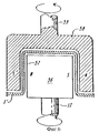
Фиг. 1 - изображение в аксонометрии теплопередающего устройства с орбитальным стержнем в соответствии с настоящим изобретением, где множество теплопередающих труб установлены неподвижно, а орбитальный привод надежно связан с контактными стержнями. FIG. 1 is a perspective view of a heat transfer device with an orbital rod in accordance with the present invention, where a plurality of heat transfer tubes are fixedly mounted and the orbital drive is securely connected to the contact rods.
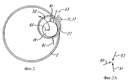
Фиг. 2 - упрощенный вид горизонтального сечения теплопередающей трубы и движущегося по орбите контактного стержня, иллюстрирующий динамические силы, действующие на стержень и жидкость в трубе. FIG. 2 is a simplified horizontal section of a heat transfer pipe and a contact rod moving in orbit, illustrating the dynamic forces acting on the rod and fluid in the pipe.
Фиг. 2A - векторная диаграмма сил, иллюстрирующая динамические силы, действующие как показано на фиг. 2. FIG. 2A is a vector force diagram illustrating dynamic forces acting as shown in FIG. 2.
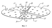
Фиг. 3 - упрощенный вид в аксонометрии двух пар диаметрально противоположных приводных плат, каждая из которых приводится в движение с помощью эксцентриковых кривошипов и каждая приспособленная для зацепления и приведения в движение по орбите ряда контактных стержней, как показано на фиг. 1. FIG. 3 is a simplified perspective view of two pairs of diametrically opposed drive plates, each of which is driven by eccentric cranks and each adapted to engage and drive a series of contact rods in orbit, as shown in FIG. 1.
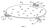
Фиг. 4 - вид в аксонометрии другого варианта привода стержня в соответствии с настоящим изобретением. FIG. 4 is a perspective view of another embodiment of a shaft drive in accordance with the present invention.
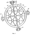
Фиг. 5 - горизонтальное сечение еще одного варианта орбитального привода в соответствии с настоящим изобретением. FIG. 5 is a horizontal section of yet another embodiment of an orbital actuator in accordance with the present invention.
Фиг. 6 - вертикальный разрез магнитной муфты для передачи усилия вращения с уплотнением иным, чем уплотнение вращающихся деталей. FIG. 6 is a vertical section through a magnetic coupling for transmitting a rotational force with a seal other than a seal of rotating parts.
Фиг. 7 - вертикальный разрез, соответствующий фиг. 6, иллюстрирующий механическое соединение для передачи усилия вращения с уплотнением иным, чем уплотнение скольжения вращающихся деталей. FIG. 7 is a vertical section corresponding to FIG. 6 illustrating a mechanical connection for transmitting a rotational force with a seal other than a sliding seal of the rotating parts.
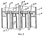
Фиг. 8 - вертикальный разрез системы распределения жидкости, используемой в устройстве по фиг. 1. FIG. 8 is a vertical section through a fluid distribution system used in the device of FIG. 1.
Фиг. 9 - вертикальный разрез установочной конструкции в соответствии с настоящим изобретением для контактных стрежней. FIG. 9 is a vertical section through an installation structure in accordance with the present invention for contact rods.
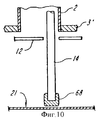
Фиг. 10 - вид, соответствующий фиг. 9, но другого варианта установочной конструкции. FIG. 10 is a view corresponding to FIG. 9, but another version of the installation design.
Подробное описание предпочтительных воплощений изобретения. Detailed description of preferred embodiments of the invention.
На фиг. 1 показано теплопередающее устройство, в котором использован привод для обеспечения движения контактного стержня по орбите, в соответствии с настоящим изобретением. Контейнер или наружный корпус 1 содержит ряд теплопередающих труб 2. Верхний лист 3 и нижний лист 3' вместе с проходящими через них трубами 2 делят внутренний объем контейнера 1 на две камеры 4 и 5. Камера 4 является наружной или корпусной стороной теплопередающей системы. Камера 5 включает обе верхнюю и нижнюю камеры 5', а также пространство внутри всех труб 2. Каждая труба 2 обеспечивает внутреннюю и наружную теплопередающие поверхности. Каждая труба имеет тонкую стенку и выполнена из материала с высокими теплопередающими свойствами, такого как медь или сталь. Труба может иметь определенную поверхностную обработку, такую как шлицовка (рифление) для улучшения теплопередающих свойств внутренней или наружной поверхностей трубы. Первая среда 1 может вводиться в камеру 4 через сопла или трубки 7, 7 для теплообмена через стенку теплопередающих трубок 2 со второй средой 11, которая может вводиться в верхнюю камеру 5 через сопла или трубки 6, 8, а также через сопла или трубки 9, 10, расположенные у нижней камеры 5'. Например, при обессоливании средой 11 является морская вода, а средой 1 - нагретый пар, такой как водяной пар. При производстве суспензий льда в качестве среды 11 используется вода с добавкой, которая уменьшает прилипание ледяных кристаллов к внутренней поверхности трубы, а в качестве среды 1 используется сжатый хладагент, который кипит у наружной поверхности трубы, образуя паропенистый поток. Пригодной для воды добавкой является этиленгликоль (автомобильный антифриз), молоко, морская вода, двойной ацетат кальция и магния и определенные неорганические соли, такие как бикарбонат натрия, которые образуют безводные кристаллы. Обычным является 10%-й раствор. Удачные добавки ведут к образованию очень тонких порошкообразных кристаллов льда. Добавки, которые не работают, образуют кристаллы льда в виде больших плоских чешуек. In FIG. 1 shows a heat transfer device in which an actuator is used to allow the contact rod to orbit in accordance with the present invention. The container or outer casing 1 contains a series of
При использовании устройства 100 для осуществления выпаривания находящаяся в камере 4 среда 1, имеющая более высокую температуру, используется для выпаривания второй среды 11, находящейся внутри камеры 5 и имеющей более низкую температуру. В частности, водяной пар может вводиться в камеру 4 через трубку 7, причем при его конденсации на наружной поверхности трубы 2 он будет выделять скрытую (латентную) теплоту с образованием некоторого количества конденсата, который будет вытекать через выход 7'. Высвобожденное таким образом тепло будет использоваться для выпаривания среды 11, причем жидкость, введенная в верхнюю камеру 5 через трубку 7 будет подаваться на верхнюю поверхность листа 3. В соответствии с одним вариантом распределения введенной жидкости она разместится на листе 3 в форме жидкостной лужи 24. Эта жидкость в виде жидкостного потока 41 будет затем стекать в трубу 2 через выемки 25, попадая на ее внутреннюю поверхность. Скрытое тепло, высвобожденное при конденсации водяного пара внутри камеры 4, будет проходить через стенку трубы 2 и выпаривать жидкостной поток 41 внутри трубы с выделением пара 44, который может выходить либо через верхний конец трубы 2 и далее через выход 8, либо в соответствии с другим вариантом идти вниз по трубе 2 вместе с жидкостным потоком 41 и выходить через сопло или трубу 9 у нижнего конца камеры 5. When using the device 100 for evaporating, the medium 1 located in the
Внутри каждой трубы 2 расположен контактный стержень 14, который приводится во вращение по орбите внутри трубы 2 для проталкивания жидкостного потока 41. Траектория и направление движения по орбите обозначены круговыми стрелками 50. Такое орбитальное движение будет генерировать центробежную силу, которая будет удерживать стержень 14 на внутренней поверхности трубы 2, который благодаря этому будет "размазывать" жидкостной поток 41 в тонкую и ровную жидкостную пленку для облегчения выпаривания потока 41 и тем самым увеличивая коэффициент теплопередачи. Inside each
Масса стержня, свойства поверхности стержня и трубы так же, как и скорость вращения стержня, должны регулироваться для достижения различных целей при различных их применениях. The mass of the rod, the properties of the surface of the rod and pipe, as well as the speed of rotation of the rod, must be adjusted to achieve different goals in their various applications.
Например, при обессоливании морской воды орбитальное движение стержня должно быть отрегулировано так, чтобы свести до минимума накипь, тенденцию к образованию которой имеют различные компоненты, растворенные в морской воде, образующие ее при выпаривании воды. В случае осуществления концентрации некоторых пищевых продуктов стержень должен быть способен проталкивать концентрированную жидкость, преодолевая ее вязкость и в то же время не повреждая тонкий материал внутри концентрата. При производстве суспензии льда поток тепла будет направлен из внутренней полости трубы к ее наружной поверхности так, чтобы по мере охлаждения жидкости образовывались и перемещались вниз кристаллы льда. Функция стержня для такого применения будет состоять в том, чтобы разрушать и/или смещать начинающиеся образовываться кристаллы льда, которые могут прилипать к внутренней поверхности трубы 2. For example, during desalination of sea water, the orbital motion of the rod should be adjusted so as to minimize scale, the tendency to form which have various components dissolved in sea water, forming it during evaporation of water. In the case of the concentration of some food products, the rod should be able to push the concentrated liquid, overcoming its viscosity and at the same time without damaging the thin material inside the concentrate. In the production of an ice slurry, a heat flow will be directed from the inner cavity of the pipe to its outer surface so that as crystals cool, ice crystals form and move downward. The function of the rod for such an application will be to destroy and / or displace ice crystals beginning to form, which may adhere to the inner surface of the
В устройстве по фиг. 1 стержни 14 предпочтительно свободно стоят внутри труб 2, причем их нижние концы опираются на плату 21, будучи предусмотрены с наконечниками, имеющими низкофрикционную поверхность для скольжения стержней по указанной плате при осуществлении орбитального движения по стрелке 50. В соответствии с предпочтительным вариантом, указанное орбитальное движение стержней 14 осуществляется посредством двух отстоящих друг от друга по вертикали горизонтальных плат 11, 12. Эти платы поддерживаются на гибких осях 13 и 13', которые у одного конца прикреплены к торцевым крышкам корпуса 1, а у другого конца к платам 11 и 12. Эти гибкие оси 13 и 13' обладают жесткостью на их кручение, но эластичностью при их изгибании. Подобным образом работает универсальный шарнир. Подвешенные таким образом платы 11 и 12 будут иметь свободу для поступательного движения, но не для кругового движения. В центре плат 11 и 12 имеются вкладыши 26 и 26', через которые проходит вал 15, приводимый во вращение посредством кривошипов 16 и 16', укрепленных на центральном валу 17 и 17', который, в свою очередь, приводится во вращение двигателем 18 через подшипники и уплотнения 28 и 28', установленные на контейнере 1. Таким образом, когда работает двигатель 18, он побуждает платы 11 и 12 двигаться по орбите, а они, в свою очередь, приводят в подобное орбитальное движение все стержни 14, охваченные отверстиями 27 и 27' этих плат. Радиус кривошипов 16 и 16' подбирается так, чтобы стержни 14 могли свободно двигаться по орбите внутри труб 2. Диаметр отверстий 27 и 27' значительно больше диаметра стержней 14, что позволяет каждому стержню саморегулироваться при его орбитальном движении в трубе 2. In the device of FIG. 1, the
На фиг. 2 показаны главные динамические силы, действующие при работе узла стержня, приводимого в движение по орбите. Сила 60 - это центробежная сила, развиваемая стержнем 14, приводимым во вращение по орбите внутри трубы 2 силой 61, возникающей при движении отверстий 27 плат 11 и 12, которые приводят в движение стержень. Эта центробежная сила взаимодействует с гидродинамической силой 63, действующей на поверхность стержня 14, когда жидкость проталкивается по трубе стержнем. На фиг. 2 показана диаграмма равновесия сил, иллюстрирующая физическую природу баланса векторов сил более ясно. По существу тангенциальный (касательный) компонент вектора 63 уравновешивается вектором 61, который имеет непосредственное отношение к приводному усилию, развиваемому двигателем 18. Радиальный компонент вектора 63 уравновешивается центробежной силой, которая является функцией скорости, диаметра и плотности стержня. Так как скорость вращения и диаметр стержня также влияют на характеристику вектора 63, независимым контрольным фактором является только плотность стержня. In FIG. 2 shows the main dynamic forces acting during operation of the rod assembly driven in orbit. The
Суммарная центробежная сила, развиваемая всеми стержнями, и сила от приводных плат создают периодически меняющуюся разрушительную силу, действующую на всю систему, сотрясая ее. Это явление может быть сведено до минимума путем использования двух противовесов 19, 19, установленных на валах 17 и 17', как показано на фиг. 1. The total centrifugal force developed by all the rods and the force from the drive plates create a periodically changing destructive force acting on the entire system, shaking it. This phenomenon can be minimized by using two counterweights 19, 19 mounted on
На фиг. 3 показано использование двух расположенных под прямым углом друг другу приводных плат 11, 11', приводимых в движение валом 17 через два комплекта эксцентриковых подшипников 30 и 31 и их соответствующие кронштейны 32 и 33. Вал 17a приводит в движение другую пару этих плат. Каждая плата имеет, в основном, форму песочных часов или цифры восемь, образуя два сектора. Плата 11 расположена на некотором расстоянии над платой 11'. Поскольку эти два эксцентриковых подшипника расположены друг относительно друга на расстоянии под углом 180o и каждая приводная плата имеет одинаковую массу и приводит в движение одинаковое количество стержней, они сами стремятся уравновесить друг друга без необходимости использования внешних противовесов.In FIG. Figure 3 shows the use of two drive plates 11, 11 'arranged at right angles to each other, driven by a
На фиг. 4 показан вариант привода стержня с использованием кривошипов 39, причем здесь взято минимум три кривошипа, расположенных треугольником для обеспечения плавной работы. На этой схеме все три кривошипа 39 имеют одинаковый радиус. Приводной плоский элемент 38 приводной платы 11'' взят тот же, что и для приводной платы 12''. Все три кривошипа при приведении во вращение одного из них будут вращаться в унисон. In FIG. 4 shows an embodiment of a rod
На фиг. 5 показан другой вариант приводной платы 11'''' для орбитального стержня, который подчеркивает возможность изготовления платы на сколько возможно легкой и платы, с помощью которой предлагается насколько возможно ограничить поток среды в трубу и из нее. Плата 11'''' выполнена из несущего кольца 11a и перемычек 11b, вместе являющихся опорой для приводных колец с отверстиями 27. Этот тип приводной платы особенно подходит для нижней платы теплопередающего устройства, используемого для получения суспензии льда. In FIG. 5 shows another embodiment of the drive plate 11 ″ ″ for the orbital rod, which emphasizes the possibility of making the board as light as possible and the board with which it is proposed to limit the flow of medium into and out of the pipe as much as possible. The board 11 ″ ″ is made of a carrier ring 11a and jumpers 11b, which together are a support for the drive rings with
На фиг. 5 показан также линейный привод, такой как магнитный или электрический соленоиды или пневматический цилиндр. Как показано на чертеже, магнитный сердечник 60 установлен с возможностью скольжения внутри цилиндра 63 и приводится в движение от расположенной снаружи цилиндра соленоидной катушки 61. Четыре указанных линейных привода образуют расположенные под прямым углом друг к другу пары. Они связаны с приводными платами 11'''', 12'''' (не показаны) тросами 62 и через пружины (не показаны) таким образом, что, когда к четырем катушкам 61 подается электрический ток требуемой частоты, приводная плата 11 приводится в движение по орбите. In FIG. 5 also shows a linear actuator, such as a magnetic or electric solenoid or pneumatic cylinder. As shown in the drawing, the
На фиг. 6 показана стандартная магнитная муфта для безуплотнительного привода, где вал 17 соединен с магнитным сердечником 56, расположенным внутри цилиндра 57, который является частью верхней крышки 1a контейнера 1. Чашеобразный магнит 58, расположенный вокруг цилиндра 57, приводится во вращение валом 59. In FIG. 6 shows a standard magnetic coupling for a sealingless drive, where the
На фиг. 7 показано механическое уплотнение нескользящего типа с использованием сильфонов (гофры) или подобных элементов. По существу, это кривошип, покрытый гибким шлангом. Здесь вал 17 приводится во вращение кривошипом 45, установленным в опорных подшипниках 28', 47 и 48, причем вращение кривошипа 45 обеспечивается за счет толкательного движения, передаваемого ему шатуном 53 (как на фиг. 4). Уплотнение кривошипа обеспечивается сильфонами 52, армированными кольцами 51. Упомянутое толкательное движение передается кривошипу через подшипниковую втулку 47. У верхнего конца кривошипа расположена трубка 54 для подачи некоторого количества соответствующей жидкости 55, обеспечивающей смазку подшипников и способствующей поддержанию герметичности уплотнения. Эта жидкость может быть частью жидкости, подаваемой на обработку. Подшипник 48 поддерживается двумя изогнутыми опорными элементами 49, 49. Это уплотнение выполнено вращающимся, но не скользящего типа. Это устройство обладает преимуществом механического привода в отличие от магнитного привода по фиг. 6, который может выходить из зацепления, если его крутящий момент не может обеспечить движение приложенной к нему нагрузки. In FIG. 7 shows a non-slip type mechanical seal using bellows (corrugations) or similar elements. Essentially, this is a crank covered with a flexible hose. Here, the
На фиг. 8 показано использование верхней приводной платы 11*, ее отверстий 27* и контактных стержней 14* для равномерного распределения подаваемой на обработку жидкости в теплопередающие трубы 2*. В этом устройстве трубы 2* собраны таким образом, чтобы немного выступать над поверхностью верхнего листа 3* с тем, чтобы позволить плате 11* скользить по верхнему торцу трубы 2*, служа в качестве крышки. Жидкость, подаваемая в камеру 5*, будет образовывать лужу 24*, которая затопит плату 11*, образуя над ней слой жидкости заданной высоты, который определит расход потока жидкости в каждую трубу через отверстие 27*, окружающее контактный стержень 14*. При таком распределении жидкости она служит и в качестве смазки для стержня в отверстии 27*, причем движение стержня способствует предотвращению любой тенденции к забиванию этих отверстий.In FIG. Figure 8 shows the use of the upper drive plate 11 * , its
На фиг. 9 и 10 показаны два альтернативных устройства для снижения трения скольжения стержня 14 по плате 21. Как показано на фиг. 9, соединительный рычаг 64 крепится к нижнему концу стержня 14 с помощью шарового шарнира 67, установленного в гнезде 66 рычага 64, позволяющего стержню свободно двигаться по орбите внутри трубы. На чертеже рычаг показан с шарниром на верхнем конце, но он на этом конце может быть предусмотрен с гнездом. Возможно использование также и других конструкций таких, как короткие отрезки гибкого троса или двойной универсальный шарнир. Нижний конец рычага 64 свободно установлен в гнезде 65, образованном в плате 21', контактируя с ним. Гнездо 65 ограничивает любое заметное боковое смещение нижнего конца рычага, но не ограничивает его движение по конической траектории по мере движения стержня по орбите. Гнездо 65 может быть выполнено в качестве отдельного чашеподобного элемента, крепящегося на плате 21'. Указанное соединительное звено могло бы быть также выполнено в форме короткого отрезка гибкого троса или двойного универсального шарнира, но это было связано с увеличением расходов, с проблемами усталости или износа материалов. In FIG. 9 and 10 show two alternative devices for reducing the sliding friction of the
На фиг. 10 показано более простое устройство. На нижнем конце стержня 14 крепится наконечник 68 из низкофрикционного материала, например соответствующей пластмассы. Такой материал имеет более низкий коэффициент трения по отношению к поверхности платы 21, чем материал стержня 14, в связи с чем уменьшается износ деталей и снижается потребление энергии, требуемой для приведения в движение стержня (стержней). In FIG. 10 shows a simpler device. At the lower end of the
При работе устройства двигатель 18 приводит в движение по орбите две или более приводных плат и стержни, удерживаемые в этих платах, благодаря чему осуществляется распределение жидкости по трубам 2 и удаление твердого осадка с внутренних стенок труб в соответствии с распределением динамических сил, показанным на фиг. 2. Благодаря эластичности контактный стержень хорошо сопрягается с внутренней поверхностью трубы и эффективно способствует хорошей теплопередаче без критического выравнивания в ряд движущихся деталей, без износа деталей, без сопряжения деталей с тугими посадками, без высокого потребления энергии и повышенных требований к сборке, монтажу, присущих известным устройствам с орбитальным движением труб. В частности, в известных системах, описанных в упомянутых патентах США N 4230529, 4441963 и 4762592, масса стержней и связанных с ними движущихся приводных деталей составляет обычно менее 10% массы движущихся труб, жидкости в трубах и других элементов, жестко связанных с трубами и двигающихся вместе с ними. Это уменьшает требования к величине крутящего момента при пуске устройства почти в пять раз, а потребность в энергии для двигателя 18 почти в два раза. Как отмечалось выше, недостатки известных жестких контактных и скребковых систем устраняются путем выполнения стержней 14 эластичными и контактными, а также благодаря конструкции привода. Уменьшенная движущаяся масса облегчает также увеличение размеров устройства, например, за счет уменьшения затрат и снижения усталости монтажных пружин и ослабления проблем вибрации и баланса устройств с орбитальным движением труб и с фиксированным кривошипом. When the device is operating, the
Хотя изобретение было описано на примерах его предпочтительных воплощений, специалисту понятно, что в вышеприведенное подробное описание изобретения и приложенные чертежи могут быть внесены различные изменения. Например, хотя контактные стержни свободно удерживаются в отверстиях приводной платы, как было описано выше, они могут быть установлены в подшипниках, хотя это будет дороже и будет связано с ограничением выбора обрабатываемых жидкостей. Кроме этого, хотя в соответствии с описанием контактные стержни свободно стоят на их нижних концах, они могут быть подвешены сверху на гибком тросе, гибко закрепленном по его обоим концам, или поддерживаться на одной или двух приводных платах. Однако полагаем, что эти изменения менее желательны, поскольку они сокращают выбор режимов работы, увеличивают затраты и связаны с большей подверженностью деталей усталости и износу. Приводные платы могут допускать разнообразие их форм, согласующихся с основными конструкциями и их назначениями, описанными здесь, так же, как и варианты источника движущей силы и его соединения с приводной платой. Эти и другие изменения и модификации попадают под объем притязаний приложенной формулы изобретения. Although the invention has been described by way of examples of its preferred embodiments, one skilled in the art will appreciate that various changes can be made to the above detailed description of the invention and the attached drawings. For example, although the contact rods are freely held in the holes of the drive plate, as described above, they can be installed in the bearings, although this will be more expensive and will be associated with a limitation of the choice of processed fluids. In addition, although in accordance with the description, the contact rods freely stand at their lower ends, they can be suspended from above on a flexible cable flexibly fixed at its both ends, or supported on one or two drive boards. However, we believe that these changes are less desirable, since they reduce the choice of operating modes, increase costs and are associated with a greater exposure of parts to fatigue and wear. Drive plates may allow a variety of their forms, consistent with the basic designs and their purposes described here, as well as options for a source of driving force and its connection with the drive plate. These and other changes and modifications fall within the scope of the appended claims.
Claims (15)
Applications Claiming Priority (4)
| Application Number | Priority Date | Filing Date | Title |
|---|---|---|---|
| US08/081,039 US5385645A (en) | 1991-06-17 | 1993-06-22 | Heat transfer apparatus with positive drive orbital whip rod |
| US08/081.039 | 1993-06-22 | ||
| US08/081,039 | 1993-06-22 | ||
| PCT/US1994/006827 WO1995000223A1 (en) | 1993-06-22 | 1994-06-16 | Heat transfer apparatus with positive drive orbital whip rod |
Publications (2)
| Publication Number | Publication Date |
|---|---|
| RU96104369A RU96104369A (en) | 1998-03-20 |
| RU2144411C1 true RU2144411C1 (en) | 2000-01-20 |
Family
ID=22161732
Family Applications (1)
| Application Number | Title | Priority Date | Filing Date |
|---|---|---|---|
| RU96104369A RU2144411C1 (en) | 1993-06-22 | 1994-06-16 | Heat-transfer device with rigid drive for contact core moving in orbit |
Country Status (21)
| Country | Link |
|---|---|
| US (1) | US5385645A (en) |
| EP (1) | EP0705126B1 (en) |
| JP (1) | JP3398384B2 (en) |
| KR (1) | KR100402180B1 (en) |
| CN (1) | CN1043849C (en) |
| AT (1) | ATE171637T1 (en) |
| AU (1) | AU678274B2 (en) |
| CA (1) | CA2165323A1 (en) |
| CZ (1) | CZ345895A3 (en) |
| DE (1) | DE69413688T2 (en) |
| DK (1) | DK0705126T3 (en) |
| ES (1) | ES2124898T3 (en) |
| FI (1) | FI956137A (en) |
| HU (1) | HU217697B (en) |
| NO (1) | NO306004B1 (en) |
| NZ (1) | NZ269024A (en) |
| PL (1) | PL175718B1 (en) |
| RU (1) | RU2144411C1 (en) |
| SG (1) | SG48409A1 (en) |
| TW (2) | TW242565B (en) |
| WO (1) | WO1995000223A1 (en) |
Families Citing this family (17)
| Publication number | Priority date | Publication date | Assignee | Title |
|---|---|---|---|---|
| US5953924A (en) * | 1991-06-17 | 1999-09-21 | Y. T. Li Engineering, Inc. | Apparatus, process and system for tube and whip rod heat exchanger |
| US5768894A (en) * | 1991-06-17 | 1998-06-23 | Y.T. Li Engineering, Inc. | Apparatus, process and system for tube and whip rod heat exchanger |
| US5513698A (en) * | 1994-06-20 | 1996-05-07 | Paul Mueller Company | Balanced drive for orbital tube whip rod heat exchanger |
| US5653852A (en) * | 1995-11-08 | 1997-08-05 | Meng; Ching Ping | Distilling device |
| US5971061A (en) * | 1998-09-21 | 1999-10-26 | Y.T. Li Engineering, Inc. | Edge-hanging orbital rod support and drive for vertical tube-type heat exchanger |
| US6318094B1 (en) | 2000-08-11 | 2001-11-20 | Paul Mueller Company | Bimetallic tube in a heat exchanger of an ice making machine |
| US6434964B1 (en) * | 2001-02-15 | 2002-08-20 | Mayekawa Mfg. Co., Ltd. | Ice-making machine and ice-making method |
| CN100357677C (en) * | 2006-02-28 | 2007-12-26 | 哈尔滨工业大学 | Cold district sewage cold-hot source sewage accompaning-heat treating device |
| KR100743268B1 (en) * | 2006-08-10 | 2007-07-27 | 한국과학기술원 | Installation fins and installation structure of fins and a heat sink with moving fins inserted between cooling fins |
| CN102397708A (en) * | 2010-09-15 | 2012-04-04 | 王仲明 | Wall-scrapping film evaporator with scraper tube |
| CN102268301B (en) * | 2011-06-24 | 2013-09-18 | 华中科技大学 | Isolated preheating device of granular material |
| CN104236098B (en) * | 2014-09-26 | 2017-01-11 | 海门黄海创业园服务有限公司 | Heat exchange water tank |
| US10674742B2 (en) * | 2015-01-06 | 2020-06-09 | Tangent Foods International Limited | System and method for making ice cream |
| CN111577082B (en) * | 2020-05-15 | 2021-09-21 | 南通海鹰木业股份有限公司 | Novel ventilation type double-bridge heat insulation bridge-cut-off window |
| US20220074684A1 (en) * | 2020-09-08 | 2022-03-10 | Suncor Energy Inc. | Tube and Tubesheet Assembly with Damage Resistance and Method for Protecting Tube and Tubesheet Assemblies from Damage |
| CN114669066B (en) * | 2022-03-24 | 2023-09-26 | 四川点石能源股份有限公司 | MVR evaporation concentration system |
| CN115445678B (en) * | 2022-08-23 | 2023-08-01 | 电子科技大学 | Method, device and application for driving magnetic fluid to horizontally move |
Family Cites Families (17)
| Publication number | Priority date | Publication date | Assignee | Title |
|---|---|---|---|---|
| US3190817A (en) * | 1957-08-12 | 1965-06-22 | Gen Electric | Compression distillation apparatus |
| NL123626C (en) * | 1961-02-08 | |||
| GB991748A (en) * | 1961-12-29 | 1965-05-12 | Vitamins Ltd | Improvements in devices for wiping surfaces and distillation apparatus including such devices |
| US3328972A (en) * | 1966-08-09 | 1967-07-04 | Struthers Scientific Int Corp | Concentration of extracts by freezing |
| US3498081A (en) * | 1968-03-15 | 1970-03-03 | Mcquay Inc | Auger ice maker |
| US4230529A (en) * | 1978-11-16 | 1980-10-28 | Li Yao T | Distillation apparatus |
| US4618399A (en) * | 1978-11-16 | 1986-10-21 | Li Yao T | Wobble tube evaporator with whip rod fluid distributor |
| US4551159A (en) * | 1979-04-03 | 1985-11-05 | Vladimir Goldstein | Ice making machine and method |
| US4441963A (en) * | 1980-10-27 | 1984-04-10 | Li Yao T | Distillation apparatus |
| US4762592A (en) * | 1980-10-27 | 1988-08-09 | Li Yao T | Orbital drive evaporator |
| CS229404B1 (en) * | 1981-06-22 | 1984-06-18 | Alexander Prof Drsc Tkac | Bloc short travel evaporator with a wiped film |
| US4468930A (en) * | 1982-04-26 | 1984-09-04 | Concentration Specialists, Inc. | Freeze crystallization subassembly |
| ZA834990B (en) * | 1982-07-20 | 1984-04-25 | Holden William J | Heat exchanger cleaner |
| US4796441A (en) * | 1985-05-30 | 1989-01-10 | Sunwell Engineering Company Limited | Ice making machine |
| FR2592924B1 (en) * | 1986-01-10 | 1989-10-20 | Total France | DEVICE FOR HOLDING THE END OF A MOBILE ELEMENT IN A POSITION, ROTATING DRIVE IN A TUBE AND APPLICATION TO PREVENTING FOULING AND CLEANING OF THIS TUBE. |
| US5165469A (en) * | 1991-05-17 | 1992-11-24 | Smith Douglas W P | High viscous fluid heat exchanger |
| US5221439A (en) * | 1991-06-17 | 1993-06-22 | Y. T. Li Engineering, Inc. | Orbital tube evaporator with improved heat transfer |
-
1993
- 1993-06-22 US US08/081,039 patent/US5385645A/en not_active Expired - Lifetime
- 1993-12-10 CN CN93120886A patent/CN1043849C/en not_active Expired - Lifetime
-
1994
- 1994-01-07 TW TW083100104A patent/TW242565B/zh active
- 1994-04-02 TW TW083102945A patent/TW311981B/zh active
- 1994-06-16 EP EP94921965A patent/EP0705126B1/en not_active Expired - Lifetime
- 1994-06-16 WO PCT/US1994/006827 patent/WO1995000223A1/en not_active Application Discontinuation
- 1994-06-16 DE DE69413688T patent/DE69413688T2/en not_active Expired - Lifetime
- 1994-06-16 HU HU9503672A patent/HU217697B/en not_active IP Right Cessation
- 1994-06-16 KR KR1019950705846A patent/KR100402180B1/en not_active IP Right Cessation
- 1994-06-16 DK DK94921965T patent/DK0705126T3/en active
- 1994-06-16 CA CA002165323A patent/CA2165323A1/en not_active Abandoned
- 1994-06-16 ES ES94921965T patent/ES2124898T3/en not_active Expired - Lifetime
- 1994-06-16 NZ NZ269024A patent/NZ269024A/en unknown
- 1994-06-16 SG SG1996009462A patent/SG48409A1/en unknown
- 1994-06-16 RU RU96104369A patent/RU2144411C1/en active
- 1994-06-16 CZ CZ953458A patent/CZ345895A3/en unknown
- 1994-06-16 AT AT94921965T patent/ATE171637T1/en not_active IP Right Cessation
- 1994-06-16 AU AU72471/94A patent/AU678274B2/en not_active Ceased
- 1994-06-16 PL PL94312273A patent/PL175718B1/en unknown
- 1994-06-16 JP JP50295895A patent/JP3398384B2/en not_active Expired - Fee Related
-
1995
- 1995-12-20 FI FI956137A patent/FI956137A/en unknown
- 1995-12-22 NO NO955293A patent/NO306004B1/en not_active IP Right Cessation
Also Published As
| Publication number | Publication date |
|---|---|
| NZ269024A (en) | 1997-10-24 |
| FI956137A (en) | 1995-12-22 |
| PL312273A1 (en) | 1996-04-15 |
| HU9503672D0 (en) | 1996-02-28 |
| EP0705126B1 (en) | 1998-09-30 |
| CN1096872A (en) | 1994-12-28 |
| NO955293L (en) | 1996-02-21 |
| EP0705126A4 (en) | 1996-10-23 |
| NO306004B1 (en) | 1999-08-30 |
| EP0705126A1 (en) | 1996-04-10 |
| AU678274B2 (en) | 1997-05-22 |
| NO955293D0 (en) | 1995-12-22 |
| FI956137A0 (en) | 1995-12-20 |
| AU7247194A (en) | 1995-01-17 |
| ES2124898T3 (en) | 1999-02-16 |
| CA2165323A1 (en) | 1995-01-05 |
| CZ345895A3 (en) | 1996-06-12 |
| SG48409A1 (en) | 1998-04-17 |
| HUT75914A (en) | 1997-05-28 |
| PL175718B1 (en) | 1999-01-29 |
| HU217697B (en) | 2000-04-28 |
| ATE171637T1 (en) | 1998-10-15 |
| DK0705126T3 (en) | 1999-06-21 |
| DE69413688T2 (en) | 1999-05-20 |
| TW242565B (en) | 1995-03-11 |
| CN1043849C (en) | 1999-06-30 |
| US5385645A (en) | 1995-01-31 |
| JP3398384B2 (en) | 2003-04-21 |
| JPH09502509A (en) | 1997-03-11 |
| DE69413688D1 (en) | 1998-11-05 |
| TW311981B (en) | 1997-08-01 |
| KR100402180B1 (en) | 2004-02-05 |
| WO1995000223A1 (en) | 1995-01-05 |
Similar Documents
| Publication | Publication Date | Title |
|---|---|---|
| RU2144411C1 (en) | Heat-transfer device with rigid drive for contact core moving in orbit | |
| US5953924A (en) | Apparatus, process and system for tube and whip rod heat exchanger | |
| JP7117874B2 (en) | flooded evaporator | |
| KR100396148B1 (en) | Tube and whip rod heat exchanger | |
| JP3416139B2 (en) | Apparatus and method for freezing or cooling liquid | |
| US5768894A (en) | Apparatus, process and system for tube and whip rod heat exchanger | |
| US9476628B2 (en) | Industrial shell and tube heat exchanger | |
| CN103007864A (en) | Stirring tank | |
| JP3691512B6 (en) | Heat exchanger, liquid freezing / cooling apparatus and method, and thermal storage system | |
| KR100341012B1 (en) | Orbital type freezing apparatus and method | |
| KR100341013B1 (en) | Tubing and whip rod heat exchangers and refrigeration or cooling methods | |
| KR200255155Y1 (en) | Vibration-Type Heat Exchanger | |
| EP0063141A1 (en) | Improved distillation apparatus | |
| KR200240789Y1 (en) | apparatus for increasing a heat transfer efficiency in a heat exchanger | |
| US3185212A (en) | Fluid heat transfer system | |
| KR20010035543A (en) | method and apparatus for increasing a heat transfer efficiency in a heat exchanger |