RU2143753C1 - Tokamak unit electromagnetic system - Google Patents
Tokamak unit electromagnetic system Download PDFInfo
- Publication number
- RU2143753C1 RU2143753C1 RU96103270A RU96103270A RU2143753C1 RU 2143753 C1 RU2143753 C1 RU 2143753C1 RU 96103270 A RU96103270 A RU 96103270A RU 96103270 A RU96103270 A RU 96103270A RU 2143753 C1 RU2143753 C1 RU 2143753C1
- Authority
- RU
- Russia
- Prior art keywords
- solenoid
- central
- supporting
- toroidal
- electromagnetic system
- Prior art date
Links
Images
Classifications
-
- Y—GENERAL TAGGING OF NEW TECHNOLOGICAL DEVELOPMENTS; GENERAL TAGGING OF CROSS-SECTIONAL TECHNOLOGIES SPANNING OVER SEVERAL SECTIONS OF THE IPC; TECHNICAL SUBJECTS COVERED BY FORMER USPC CROSS-REFERENCE ART COLLECTIONS [XRACs] AND DIGESTS
- Y02—TECHNOLOGIES OR APPLICATIONS FOR MITIGATION OR ADAPTATION AGAINST CLIMATE CHANGE
- Y02E—REDUCTION OF GREENHOUSE GAS [GHG] EMISSIONS, RELATED TO ENERGY GENERATION, TRANSMISSION OR DISTRIBUTION
- Y02E30/00—Energy generation of nuclear origin
- Y02E30/10—Nuclear fusion reactors
Landscapes
- Plasma Technology (AREA)
- Particle Accelerators (AREA)
Abstract
Description
Изобретение относится к экспериментальным установкам управляемого термоядерного синтеза с магнитным удержанием плазмы. The invention relates to experimental installations of controlled thermonuclear fusion with magnetic plasma confinement.
Известен проект электромагнитной системы (ЭМС) установки типа токамак, состоящей из обмотки тороидального поля (ОТП) и обмотки полоидального поля (ОПП), в состав которой входит катушка индуктора. Индуктор расположен в центральном отверстии, образованном витками ОТП. Внутри ОТП установлена тороидальная разрядная камера [1]. Такая система подвергается действию электромагнитных (пондеромоторных) сил, возникающих в результате взаимодействия тороидального магнитного поля с током ОТП, а также от взаимодействия магнитного поля катушки индуктора с собственным током [2]. Центральный индуктор или, как его принято называть в современной литературе, центральный соленоид, устанавливается в таких установках симметрично относительно горизонтальной оси установки. Он предназначен для создания центрального магнитного потока, генерирующего вихревую ЭДС для поджига разряда плазмы и поддержания ее горения в разрядной камере. Под действием вертикальной составляющей пондеромоторной силы центральный соленоид сжимается, в результате чего его длина уменьшается. При этом происходит смещение витков катушки соленоида с током и, соответственно, искажается конфигурация и изменяется величина полоидального поля (по сравнению с расчетным значением) в зоне образования плазмы, что приводит к срыву плазмы. Для устранения этого в ОПП устанавливаются дополнительные компенсирующие витки. A known project of an electromagnetic system (EMC) of a tokamak-type installation consisting of a toroidal field winding (OTP) and a poloidal field winding (OPP), which includes an inductor coil. The inductor is located in the Central hole formed by turns of OTP. A toroidal discharge chamber [1] is installed inside the OTP. Such a system is subjected to the action of electromagnetic (ponderomotive) forces arising as a result of the interaction of a toroidal magnetic field with an OTP current, as well as from the interaction of the magnetic field of the inductor coil with its own current [2]. The central inductor or, as it is commonly called in modern literature, the central solenoid is installed in such installations symmetrically with respect to the horizontal axis of the installation. It is designed to create a central magnetic flux that generates a vortex EMF to ignite the plasma discharge and maintain its combustion in the discharge chamber. Under the action of the vertical component of the ponderomotive force, the central solenoid contracts, as a result of which its length decreases. In this case, the coils of the solenoid coil are shifted with the current and, accordingly, the configuration is distorted and the magnitude of the poloidal field changes (compared with the calculated value) in the plasma formation zone, which leads to plasma disruption. To eliminate this, additional compensating turns are installed in the OPP.
Известна ЭМС сферического токамака MAST, содержащая центральный соленоид и обмотки полоидального и тороидального магнитных полей, расположенные на тороидальной разрядной камере. Центральный соленоид установлен вертикально между опорными элементами, равноотстоящими от горизонтальной оси установки, и намотан на центральную часть витков ОТП. Выводные концы центрального соленоида выведены вверх и вниз и жестко закреплены на разрядной камере [3]. Недостатком этой ЭМС является возможность срыва плазмы во время ее поджига в результате изменения конфигурации и величины полоидального магнитного поля в зоне образования плазмы из-за уменьшения длины центрального соленоида под действием вертикальной составляющей пондеромоторной силы. Для зажигания плазмы в зоне ее образования необходимо иметь минимальную величину фонового полоидального поля порядка 1-3 Гс [3]. Такая величина поля специально обеспечивается путем сложения магнитных полоидальных полей от протекания в момент зажигания требуемых величин токов во всех катушках полоидального поля с учетом их геометрического положения. Ввиду, как правило, большой длины центрального соленоида (например, в сферическом токамаке MAST, его длина около 3,5 м), уменьшение длины соленоида достигает десятков миллиметров (для MAST эта величина около 16 мм). Остальные катушки ОПП не имеют такой деформации, ввиду существенно меньшего размера высоты. Соответственно, при таких изменениях положения токовых витков центрального соленоида, изменяются конфигурация и величина полоидального поля~ на 5-10 Гс, что соответственно и приводит к срыву плазмы. В сферическом токамаке этот фактор проявляется в наибольшей степени ввиду малого аспектного отношения (близкое расположение плазмы к центральной оси установки и соответственно к центральному соленоиду). Для борьбы с этим явлением в установке устанавливаются компенсирующие витки. Known EMC of the spherical tokamak MAST, containing a central solenoid and windings of poloidal and toroidal magnetic fields located on a toroidal discharge chamber. The central solenoid is mounted vertically between the supporting elements equally spaced from the horizontal axis of the installation, and wound on the central part of the turns of the OTP. The output ends of the central solenoid are brought up and down and are rigidly fixed to the discharge chamber [3]. The disadvantage of this EMC is the possibility of plasma breakdown during its ignition as a result of a change in the configuration and magnitude of the poloidal magnetic field in the plasma formation zone due to a decrease in the length of the central solenoid under the action of the vertical component of the ponderomotive force. To ignite a plasma in the zone of its formation, it is necessary to have a minimum background poloidal field of the order of 1-3 G [3]. This field value is specially provided by adding the magnetic poloidal fields from the flow at the moment of ignition of the required current values in all the coils of the poloidal field, taking into account their geometric position. Due to the generally large length of the central solenoid (for example, in the spherical MAST tokamak, its length is about 3.5 m), the decrease in the length of the solenoid reaches tens of millimeters (for MAST this value is about 16 mm). The remaining OPP coils do not have such deformation, due to the significantly smaller height. Accordingly, with such changes in the position of the current turns of the central solenoid, the configuration and magnitude of the poloidal field change by 5–10 G, which leads to plasma disruption. In a spherical tokamak, this factor manifests itself to the greatest extent due to the small aspect ratio (close proximity of the plasma to the central axis of the setup and, accordingly, to the central solenoid). To combat this phenomenon, compensating coils are installed in the installation.
Кроме того, из-за уменьшения длины соленоида подвергаются деформации выводные концы соленоида, жестко закрепленные на разрядной камере. Появляющиеся в них дополнительные механические напряжения снижают ресурс работы соленоида ввиду циклического характера работы установки. In addition, due to the reduction in the length of the solenoid, the output ends of the solenoid are rigidly fixed to the discharge chamber. The additional mechanical stresses appearing in them reduce the service life of the solenoid due to the cyclic nature of the installation.
Таким образом, имеется задача избежать отклонений допустимой минимальной величины полоидального магнитного поля в зоне образования плазмы, когда центральный соленоид, после включения установки, получит вертикальную деформацию от действия пондеромоторной силы. Thus, the task is to avoid deviations of the permissible minimum value of the poloidal magnetic field in the plasma formation zone, when the central solenoid, after the installation is turned on, receives vertical deformation from the action of the ponderomotive force.
Эта задача решается тем, что в ЭМС термоядерной установки типа токамак, содержащей центральный соленоид, установленный вертикально между опорными элементами, и обмотки полоидального и тороидального магнитных полей, расположенные на тороидальной разрядной камере, опорная поверхность одного из опорных элементов центрального соленоида смещена в сторону горизонтальной оси установки на половину величины вертикальной деформации соленоида, возникающей под действием пондеромоторных сил. Один торец соленоида непосредственно примыкает к этому опорному элементу, а между другим опорным элементом и вторым торцем соленоида установлен упругий элемент. Выводы центрального соленоида в такой ЭМС целесообразно располагать вблизи торца, непосредственно примыкающего к опорному элементу. This problem is solved in that in an EMF of a tokamak-type thermonuclear installation containing a central solenoid mounted vertically between the support elements and windings of poloidal and toroidal magnetic fields located on a toroidal discharge chamber, the supporting surface of one of the supporting elements of the central solenoid is biased towards the horizontal axis installation at half the magnitude of the vertical deformation of the solenoid arising under the action of ponderomotive forces. One end of the solenoid is directly adjacent to this supporting element, and an elastic element is installed between the other supporting element and the second end of the solenoid. It is advisable to place the conclusions of the central solenoid in such an EMC near the end face immediately adjacent to the supporting element.
Техническим результатом, достигаемым при использовании изобретения, является упрощение ЭМС за счет устранения необходимости применения компенсирующих витков и механических узлов их крепления. Это приводит к снижению трудоемкости изготовления, упрощению наладки системы и экономии электроэнергии, а также к повышению ресурса работы центрального соленоида, ввиду того, что выводы при работе соленоида находятся в неподвижном состоянии, т.к. устранено перемещение торца соленоида, на котором они расположены, и отсутствуют дополнительные механические напряжения. The technical result achieved by using the invention is to simplify the EMC by eliminating the need for compensating coils and mechanical assemblies for their fastening. This leads to a decrease in the complexity of manufacturing, simplification of system setup and energy saving, as well as to an increase in the service life of the central solenoid, since the conclusions during the operation of the solenoid are stationary, because the movement of the end face of the solenoid on which they are located is eliminated, and there are no additional mechanical stresses.
На фиг. 1 приведено схематическое изображение конструкции ЭМС, выполненной в соответствии с изобретением. In FIG. 1 is a schematic illustration of an EMC structure constructed in accordance with the invention.
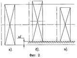
На фиг. 2 представлены три варианта положения центрального соленоида:
а) положение соленоида в конструкции прототипа;
б) положение соленоида в изобретении при сборке ЭМС;
в) положение соленоида в изобретении после включения установки.In FIG. 2 presents three options for the position of the central solenoid:
a) the position of the solenoid in the design of the prototype;
b) the position of the solenoid in the invention when assembling the EMC;
c) the position of the solenoid in the invention after turning on the installation.
ЭМС термоядерной установки токамак (фиг. 1) выполнена следующим образом. На тороидальной разрядной камере 1 расположены обмотки 2 полоидального магнитного поля и обмотка 3 тороидального магнитного поля. Центральный соленоид 4 намотан на центральную часть витков обмотки 2 и установлен между опорными элементами 5 и 6. Опорная поверхность нижнего опорного элемента 6 смещена на половину величины деформации соленоида в сторону горизонтальной оси установки (фиг. 2, б, в), а нижний торец соленоида 4 непосредственно установлен на этой опорной поверхности. Между верхним опорным элементом 5 и верхним торцом соленоида 4 установлен упругий элемент 7, выполненный, например, в виде пружин, равномерно расположенных по верхнему торцу соленоида. Выводные концы 8 соленоида 4 расположены на нижнем его конце и закреплены на витках ОТП 3 или на опорных элементах, на которых стоит ЭМС. Таким образом, верхний опорный элемент 5 отстоит от нижнего опорного элемента 6 на величину длины соленоида 4 и пространства, необходимого для установки пружин упругого элемента 7. EMC thermonuclear installation tokamak (Fig. 1) is made as follows. On the toroidal discharge chamber 1 are located the windings 2 of the poloidal magnetic field and the winding 3 of the toroidal magnetic field. The central solenoid 4 is wound on the central part of the turns of the winding 2 and installed between the supporting
Величина смещения опорной поверхности нижнего опорного элемента 6, а следовательно, и нижнего торца соленоида 4 расчитывается следующим образом [4]:
![]()
где Δl - половинная величина деформации соленоида, происходящая под действием пондеромоторной силы (м);
P - электромагнитная сжимающая сила, действующая на соленоид, после первичного включения установки (Н);
lпр - суммарная высота (длина) витков проводника соленоида (м);
lиз - суммарная толщина межвитковой изоляции соленоида (м);
F - площадь поперечного сечения соленоида (м2);
Eпр - модуль упругости материала проводника соленоида (Н/м2);
Eиз - модуль упругости материала изоляции соленоида (Н/м2).The magnitude of the displacement of the supporting surface of the lower supporting
![]()
where Δl is the half value of the deformation of the solenoid that occurs under the action of the ponderomotive force (m);
P - electromagnetic compressive force acting on the solenoid, after the initial inclusion of the installation (N);
l CR - the total height (length) of the turns of the conductor of the solenoid (m);
l from - the total thickness of the interturn isolation of the solenoid (m);
F is the cross-sectional area of the solenoid (m 2 );
E CR - the modulus of elasticity of the material of the conductor of the solenoid (N / m 2 );
E from - the elastic modulus of the insulation material of the solenoid (N / m 2 ).
Работа установки происходит следующим образом. The installation is as follows.
При первой подаче электропитания на установку включаются обмотки 2 и 3 (ОПП и ОТП), в катушках которых начинает протекать электрический ток по заданной программе. К моменту зажигания плазмы в плазменном пространстве вакуумной разрядной камеры 1 наводится вихревая ЭДС и создается необходимая конфигурация полоидального магнитного поля. При этом центральный соленоид 4, заранее установленный со смещением торца на половину величины механической деформации по отношению к горизонтальной оси симметрии (фиг. 2б), сжимается от действия пондеромоторных сил и приходит в строго симметричное (относительно горизонтальной оси) положение (фиг. 2в), обеспечивая симметричное распределение полоидального поля и требуемую его величину. Упругий элемент 7 обеспечивает постоянное поджатие торца соленоида 4 с выводами 8 к нижнему опорному элементу 6. Это поджатие обеспечивает неподвижность торца с выводами независимо от величины перемещения при механической деформации другого торца центрального соленоида 4. В результате неподвижными оказываются выводы 8 соленоида и дополнительные механические напряжения в них отсутствуют. Далее происходит зажигание (пробой) газа, находящегося в разрядной камере 1, образование плазменного шнура и дальнейший разогрев плазмы. При этом обмотка 2 полоидального поля поддерживает разогрев плазмы и обеспечивает устойчивость ее положения, за счет изменений величин токов в катушках, согласно требуемому режиму работы. At the first power supply to the installation, windings 2 and 3 (OPP and OTP) are turned on, in the coils of which an electric current begins to flow according to a given program. By the time of ignition of the plasma in the plasma space of the vacuum discharge chamber 1, a vortex EMF is induced and the necessary configuration of a poloidal magnetic field is created. In this case, the central solenoid 4, pre-installed with the end face offset by half the amount of mechanical deformation with respect to the horizontal axis of symmetry (Fig. 2b), is compressed by the action of the ponderomotive forces and comes into a strictly symmetric (relative to the horizontal axis) position (Fig. 2c), providing a symmetric distribution of the poloidal field and its required value. The elastic element 7 provides a constant compression of the end face of the solenoid 4 with terminals 8 to the
Источники информации
1. Ваулина И.Г. и др. О расчете электромагнитной системы установки Т-20. Доклады Всесоюзной конференции по инженерным проблемам термоядерных реакторов. ГКИАЭ СССР, НИИЭФА. - Л.: 1977, т. 1, с. 265-273.Sources of information
1. Vaulina I.G. and others. On the calculation of the electromagnetic system of the T-20 installation. Reports of the All-Union Conference on Engineering Problems of Thermonuclear Reactors. GKIAE USSR, NIIEFA. - L .: 1977, v. 1, p. 265-273.
2. Лагутин А.С., Ожогин В.И. Сильные импульсные магнитные поля в физическом эксперименте. - М.: Энергоатомиздат, 1988. 2. Lagutin A.S., Ozhogin V.I. Strong pulsed magnetic fields in a physical experiment. - M .: Energoatomizdat, 1988.
3. Darke A.C. et al. MAST: A Mega Amp. Spherical Tokamak - Fusion Technology 1994. Proceeings of the 18th Simposium on Fusion Technology, Karlsruhe, Germany, 22-26 August 1994; North-Holland, 1995, vol. 1, p. 799-802. 3. Darke A.C. et al. MAST: A Mega Amp. Spherical Tokamak - Fusion Technology 1994. Proceeings of the 18th Simposium on Fusion Technology, Karlsruhe, Germany, August 22-26, 1994; North-Holland, 1995, vol. 1, p. 799-802.
4. Феодосьев В.И. Сопротивление материалов. - М.: Наука, 1979. 4. Feodosiev V.I. Strength of materials. - M.: Science, 1979.
Claims (2)
Priority Applications (1)
| Application Number | Priority Date | Filing Date | Title |
|---|---|---|---|
| RU96103270A RU2143753C1 (en) | 1996-02-20 | 1996-02-20 | Tokamak unit electromagnetic system |
Applications Claiming Priority (1)
| Application Number | Priority Date | Filing Date | Title |
|---|---|---|---|
| RU96103270A RU2143753C1 (en) | 1996-02-20 | 1996-02-20 | Tokamak unit electromagnetic system |
Publications (2)
| Publication Number | Publication Date |
|---|---|
| RU96103270A RU96103270A (en) | 1998-05-10 |
| RU2143753C1 true RU2143753C1 (en) | 1999-12-27 |
Family
ID=20177155
Family Applications (1)
| Application Number | Title | Priority Date | Filing Date |
|---|---|---|---|
| RU96103270A RU2143753C1 (en) | 1996-02-20 | 1996-02-20 | Tokamak unit electromagnetic system |
Country Status (1)
| Country | Link |
|---|---|
| RU (1) | RU2143753C1 (en) |
Cited By (1)
| Publication number | Priority date | Publication date | Assignee | Title |
|---|---|---|---|---|
| RU2557090C2 (en) * | 2013-04-30 | 2015-07-20 | Федеральное государственное бюджетное учреждение науки Институт ядерной физики им. Г.И. Будкера Сибирского отделения РАН (ИЯФ СО РАН) | Superconducting solenoid with corrugated magnetic field for plasma retention |
Citations (3)
| Publication number | Priority date | Publication date | Assignee | Title |
|---|---|---|---|---|
| SU689444A1 (en) * | 1978-07-28 | 1982-12-30 | Предприятие П/Я А-8904 | Method and apparatus for rd energy in thermonuclear tokamak reactor |
| US5038052A (en) * | 1987-11-17 | 1991-08-06 | Mitsubishi Denki Kabushiki Kaisha | Double swing power unit |
| FR2681228A1 (en) * | 1991-09-18 | 1993-03-19 | Grouiller Herve | Comb which can be adapted without adjustment to the diameter of the hair in order to remove lice, nits, dandruff and other foreign bodies from the hair |
-
1996
- 1996-02-20 RU RU96103270A patent/RU2143753C1/en active
Patent Citations (3)
| Publication number | Priority date | Publication date | Assignee | Title |
|---|---|---|---|---|
| SU689444A1 (en) * | 1978-07-28 | 1982-12-30 | Предприятие П/Я А-8904 | Method and apparatus for rd energy in thermonuclear tokamak reactor |
| US5038052A (en) * | 1987-11-17 | 1991-08-06 | Mitsubishi Denki Kabushiki Kaisha | Double swing power unit |
| FR2681228A1 (en) * | 1991-09-18 | 1993-03-19 | Grouiller Herve | Comb which can be adapted without adjustment to the diameter of the hair in order to remove lice, nits, dandruff and other foreign bodies from the hair |
Non-Patent Citations (1)
| Title |
|---|
| Darkes A.C. et.al.Mast: A Mega Amp. Spherical Tokamak - Fusion Technology 1994. Proceeings of the 18 th Simposium on Fusion Technology. - Karlsruhe: Germany, 22 - 26 August 1994, North-Hollaand 1995, vol. 1, p. 799-802. * |
Cited By (1)
| Publication number | Priority date | Publication date | Assignee | Title |
|---|---|---|---|---|
| RU2557090C2 (en) * | 2013-04-30 | 2015-07-20 | Федеральное государственное бюджетное учреждение науки Институт ядерной физики им. Г.И. Будкера Сибирского отделения РАН (ИЯФ СО РАН) | Superconducting solenoid with corrugated magnetic field for plasma retention |
Similar Documents
| Publication | Publication Date | Title |
|---|---|---|
| US4560528A (en) | Method and apparatus for producing average magnetic well in a reversed field pinch | |
| EP0081952B1 (en) | Multipole pinch method and apparatus for producing average magnetic well in plasma confinement | |
| CN109209804B (en) | Magnetic shield/discharge channel integrated structure of a Hall thruster | |
| JP4521394B2 (en) | Wave power generation assembly with electromagnetic damping means | |
| US11716003B1 (en) | Electromagnetic arrays | |
| JPH05273323A (en) | Magnet device | |
| RU2143753C1 (en) | Tokamak unit electromagnetic system | |
| EP0283880A1 (en) | Electrically controlled spring element | |
| CN103632898A (en) | Electromagnetic trip and residual current operated circuit breaker adopting the same | |
| US7873135B2 (en) | Method and apparatus for mitigating vibration in a nuclear reactor component | |
| CN112400209A (en) | Medium voltage circuit breaker with vacuum interrupter and drive device and method for operating a medium voltage circuit breaker | |
| CN119542099B (en) | A compact magnetic deflection system for neutral beam injection | |
| KR900000430B1 (en) | Electromagnetic actuator | |
| RU2545163C1 (en) | Vacuum circuit breaker | |
| EP3997716B1 (en) | Shielding structures in plasma environment | |
| EP0041126A2 (en) | Mosaic printing head with cross-talk prevention means | |
| US2952802A (en) | Electromagnetic release mechanism | |
| US4613477A (en) | Method of repositioning annular spacers in calandria structures and apparatus therefor | |
| RU2022167C1 (en) | Plasma engine with closed drift of electrons | |
| EP3979475A1 (en) | Switched reluctance machine | |
| CN109236858B (en) | Three-degree-of-freedom axial magnetic bearing | |
| EP0146494B1 (en) | Method of repositioning annular spacers in calandria structures, and apparatus therefor | |
| CN117393269B (en) | Linear electromagnetic force generating device for micro-thrust calibration | |
| EP0238456A2 (en) | Apparatus for simultaneously generating an intense toroidal magnetic field and an intense poloidal magnetic field quasi-stationarily in time | |
| RU2143754C1 (en) | Method for assembling electromagnetic system of tokamak unit |