RU2139615C1 - Input/output module for data bus - Google Patents
Input/output module for data bus Download PDFInfo
- Publication number
- RU2139615C1 RU2139615C1 RU95100763A RU95100763A RU2139615C1 RU 2139615 C1 RU2139615 C1 RU 2139615C1 RU 95100763 A RU95100763 A RU 95100763A RU 95100763 A RU95100763 A RU 95100763A RU 2139615 C1 RU2139615 C1 RU 2139615C1
- Authority
- RU
- Russia
- Prior art keywords
- bus
- terminals
- input
- terminal
- output module
- Prior art date
Links
- 239000004020 conductor Substances 0.000 claims abstract description 20
- 238000009434 installation Methods 0.000 claims description 12
- 230000005540 biological transmission Effects 0.000 abstract 1
- 239000000126 substance Substances 0.000 abstract 1
- 238000000034 method Methods 0.000 description 5
- 239000011810 insulating material Substances 0.000 description 4
- 241000196324 Embryophyta Species 0.000 description 1
- 241001520299 Phascolarctos cinereus Species 0.000 description 1
- 241000233805 Phoenix Species 0.000 description 1
- 230000015572 biosynthetic process Effects 0.000 description 1
- 239000012050 conventional carrier Substances 0.000 description 1
- 238000011900 installation process Methods 0.000 description 1
- 239000012774 insulation material Substances 0.000 description 1
- 230000001681 protective effect Effects 0.000 description 1
Images
Classifications
-
- G—PHYSICS
- G06—COMPUTING; CALCULATING OR COUNTING
- G06F—ELECTRIC DIGITAL DATA PROCESSING
- G06F3/00—Input arrangements for transferring data to be processed into a form capable of being handled by the computer; Output arrangements for transferring data from processing unit to output unit, e.g. interface arrangements
-
- G—PHYSICS
- G06—COMPUTING; CALCULATING OR COUNTING
- G06F—ELECTRIC DIGITAL DATA PROCESSING
- G06F1/00—Details not covered by groups G06F3/00 - G06F13/00 and G06F21/00
- G06F1/16—Constructional details or arrangements
- G06F1/18—Packaging or power distribution
- G06F1/183—Internal mounting support structures, e.g. for printed circuit boards, internal connecting means
- G06F1/185—Mounting of expansion boards
-
- G—PHYSICS
- G06—COMPUTING; CALCULATING OR COUNTING
- G06F—ELECTRIC DIGITAL DATA PROCESSING
- G06F1/00—Details not covered by groups G06F3/00 - G06F13/00 and G06F21/00
- G06F1/16—Constructional details or arrangements
- G06F1/18—Packaging or power distribution
- G06F1/183—Internal mounting support structures, e.g. for printed circuit boards, internal connecting means
- G06F1/184—Mounting of motherboards
-
- G—PHYSICS
- G06—COMPUTING; CALCULATING OR COUNTING
- G06F—ELECTRIC DIGITAL DATA PROCESSING
- G06F1/00—Details not covered by groups G06F3/00 - G06F13/00 and G06F21/00
- G06F1/16—Constructional details or arrangements
- G06F1/18—Packaging or power distribution
- G06F1/183—Internal mounting support structures, e.g. for printed circuit boards, internal connecting means
- G06F1/186—Securing of expansion boards in correspondence to slots provided at the computer enclosure
-
- H—ELECTRICITY
- H01—ELECTRIC ELEMENTS
- H01R—ELECTRICALLY-CONDUCTIVE CONNECTIONS; STRUCTURAL ASSOCIATIONS OF A PLURALITY OF MUTUALLY-INSULATED ELECTRICAL CONNECTING ELEMENTS; COUPLING DEVICES; CURRENT COLLECTORS
- H01R9/00—Structural associations of a plurality of mutually-insulated electrical connecting elements, e.g. terminal strips or terminal blocks; Terminals or binding posts mounted upon a base or in a case; Bases therefor
- H01R9/22—Bases, e.g. strip, block, panel
- H01R9/24—Terminal blocks
- H01R9/26—Clip-on terminal blocks for side-by-side rail- or strip-mounting
- H01R9/2675—Electrical interconnections between two blocks, e.g. by means of busbars
-
- H—ELECTRICITY
- H05—ELECTRIC TECHNIQUES NOT OTHERWISE PROVIDED FOR
- H05K—PRINTED CIRCUITS; CASINGS OR CONSTRUCTIONAL DETAILS OF ELECTRIC APPARATUS; MANUFACTURE OF ASSEMBLAGES OF ELECTRICAL COMPONENTS
- H05K7/00—Constructional details common to different types of electric apparatus
- H05K7/14—Mounting supporting structure in casing or on frame or rack
- H05K7/1462—Mounting supporting structure in casing or on frame or rack for programmable logic controllers [PLC] for automation or industrial process control
- H05K7/1468—Mechanical features of input/output (I/O) modules
-
- H—ELECTRICITY
- H05—ELECTRIC TECHNIQUES NOT OTHERWISE PROVIDED FOR
- H05K—PRINTED CIRCUITS; CASINGS OR CONSTRUCTIONAL DETAILS OF ELECTRIC APPARATUS; MANUFACTURE OF ASSEMBLAGES OF ELECTRICAL COMPONENTS
- H05K7/00—Constructional details common to different types of electric apparatus
- H05K7/14—Mounting supporting structure in casing or on frame or rack
- H05K7/1462—Mounting supporting structure in casing or on frame or rack for programmable logic controllers [PLC] for automation or industrial process control
- H05K7/1475—Bus assemblies for establishing communication between PLC modules
- H05K7/1478—Bus assemblies for establishing communication between PLC modules including a segmented bus
-
- H—ELECTRICITY
- H01—ELECTRIC ELEMENTS
- H01R—ELECTRICALLY-CONDUCTIVE CONNECTIONS; STRUCTURAL ASSOCIATIONS OF A PLURALITY OF MUTUALLY-INSULATED ELECTRICAL CONNECTING ELEMENTS; COUPLING DEVICES; CURRENT COLLECTORS
- H01R4/00—Electrically-conductive connections between two or more conductive members in direct contact, i.e. touching one another; Means for effecting or maintaining such contact; Electrically-conductive connections having two or more spaced connecting locations for conductors and using contact members penetrating insulation
- H01R4/28—Clamped connections, spring connections
- H01R4/48—Clamped connections, spring connections utilising a spring, clip, or other resilient member
- H01R4/4809—Clamped connections, spring connections utilising a spring, clip, or other resilient member using a leaf spring to bias the conductor toward the busbar
- H01R4/48185—Clamped connections, spring connections utilising a spring, clip, or other resilient member using a leaf spring to bias the conductor toward the busbar adapted for axial insertion of a wire end
-
- Y—GENERAL TAGGING OF NEW TECHNOLOGICAL DEVELOPMENTS; GENERAL TAGGING OF CROSS-SECTIONAL TECHNOLOGIES SPANNING OVER SEVERAL SECTIONS OF THE IPC; TECHNICAL SUBJECTS COVERED BY FORMER USPC CROSS-REFERENCE ART COLLECTIONS [XRACs] AND DIGESTS
- Y10—TECHNICAL SUBJECTS COVERED BY FORMER USPC
- Y10S—TECHNICAL SUBJECTS COVERED BY FORMER USPC CROSS-REFERENCE ART COLLECTIONS [XRACs] AND DIGESTS
- Y10S439/00—Electrical connectors
- Y10S439/928—Modular electrically interengaging parts, e.g. stove with replaceable heating elements formed on coupling parts
Abstract
Description
Изобретение касается модуля ввода/вывода для шины данных, каким он предлагается различными изготовителями в виде так называемой шины массива в сочетании со специальными процессорными системами, промышленными компьютерами и т.д., например, для управления, визуализации хода процесса, машинами, установками и для системной техники, предусмотренной для помещений. The invention relates to an input / output module for a data bus, as it is proposed by various manufacturers in the form of a so-called array bus in combination with special processor systems, industrial computers, etc., for example, for controlling, visualizing the process, machines, installations and for system equipment for indoor use.
Из проспекта фирмы Сименс "Die grossen Sparer - das System KOALA", 1993 г. известна концепция шины массива, представляющая собой рациональный вид монтажа машин и установок. Модули ввода/вывода (E/A-модули) оборудованы местами для подсоединения клемм для осуществления параллельного монтажа отдельных пользователей шины, приводных головок, сенсорных датчиков и прочей аппаратуры. From the Siemens brochure "Die grossen Sparer - das System KOALA", 1993, the concept of an array bus is known, which is a rational view of the installation of machines and plants. I / O modules (E / A modules) are equipped with terminals for connecting to parallel installation of individual users of the bus, drive heads, sensor sensors and other equipment.
Монтаж может быть реализован в любой желаемой технике подключения, например, с одним, двумя, тремя и четырьмя проводниками. Что касается зажимов подключения, то здесь пригодны особенно просто обслуживаемые пружинные зажимы или же винтовые клеммы. Installation can be implemented in any desired connection technique, for example, with one, two, three and four conductors. As regards the connection terminals, spring-loaded terminals or screw terminals are particularly suitable here.
Модули оборудованы электроникой ввода/вывода, которая соединяет пользователей, подключенных к клеммам модулей, с последовательным проводником шины данных, который может быть, например, простым двухпроволочным проводником или же световодом. The modules are equipped with I / O electronics, which connects users connected to the terminals of the modules with a serial conductor of the data bus, which can be, for example, a simple two-wire conductor or a light guide.
При этом на практике этот проводник шины данных, подключенный к модулям ввода/вывода, является большей частью независимой подшиной в топологии кольца, которая через главную шину подключена к шине массива (дистанционная шина). Главная шина управляет отдельными модулями ввода/вывода, которые могут комбинироваться друг с другом в любой последовательности и размещаться в кольце в любых позициях. At the same time, in practice, this data bus conductor connected to the input / output modules is, for the most part, an independent subplane in the ring topology, which is connected via the main bus to the array bus (remote bus). The main bus controls individual I / O modules, which can be combined with each other in any sequence and placed in the ring at any position.
Из проспекта фирмы Phoenix Contact "Neuheiten zu Teilkatalog 11 INTERBUS", 1993 известна установка модулей ввода/вывода на обычные имеющиеся в продаже несущие шины. Известно также одновременное с процессом установки автоматическое соединение с проводником шины данных и с линиями энергоснабжения, которые снабжают электронику ввода/вывода обычным напряжением, примерно 24 B DC. It is known from Phoenix Contact's brochure "Neuheiten zu
Для этой цели у основания несущих шин обычно в форме колпака смонтированы отдельные печатные платы, которые связаны друг с другом в одну так называемую питающую шину. Наряду с двумя проводами для токоснабжения на питающей шине имеются три дополнительных провода для шины данных. Контактирование проводов осуществляется через штепсельные контакты, которые жестко встроены в питающую шину на определенном раствором расстоянии. For this purpose, at the base of the carrier busbars, usually in the form of a cap, individual printed circuit boards are mounted, which are connected to each other in one so-called supply bus. In addition to the two wires for current supply, there are three additional wires for the data bus on the supply bus. The contacting of the wires is carried out through the plug contacts, which are rigidly integrated into the supply bus at a distance determined by the solution.
Такая питающая шина, интегрированная в несущую шину, не только повышает стоимостные и монтажные затраты, связанные с креплением несущей шины модулей ввода/вывода (неиспользованные частичные участки должны быть закрыты), но одновременно препятствует ее модульности, так как ширина модулей ввода/вывода всегда должна быть в несколько раз больше заданных растровых расстояний штепсельных контактов в питающей шине. Such a supply bus integrated into the carrier bus not only increases the cost and installation costs associated with attaching the I / O carrier bus (unused partial sections must be closed), but at the same time prevents its modularity, since the width of the I / O modules must always be several times greater than the specified raster distances of the plug contacts in the supply bus.
Питающая шина, размещенная у основания несущей шины, затрудняет также крепление самой несущей шины на монтажной поверхности, так как необходимые для этого отверстия под винты допускаются только на вполне определенных местах питающей шины, что на практике не совпадает с действительными условиями. The supply bus located at the base of the carrier bus also makes it difficult to mount the carrier bus on the mounting surface, since the screw holes required for this are allowed only at well-defined locations on the supply bus, which in practice does not match the actual conditions.
Названных выше недостатков можно избежать в других известных модулях ввода/вывода, которые крепятся на несущих шинах, а именно, с помощью того, что их крепят на неизменяющихся, имеющихся в свободной продаже несущих шинах, а проводники шины данных и провода токоснабжения для электроники ввода/вывода соединяют в форме плоского ленточного кабеля со штепсельным разъемом, переходя от модуля к модулю. The disadvantages mentioned above can be avoided in other known input / output modules that are mounted on carrier buses, namely, by using them on fixed, commercially available carrier buses, and data bus conductors and current supply wires for input / output electronics the output is connected in the form of a flat ribbon cable with a plug connector, passing from module to module.
Однако, этот процесс представляет для пользователя весьма затруднительную и связанную с большими временными затратами работу по монтажу, и, вероятно, по этой причине изготовитель этой системы решил предложить очень широкие модули ввода/вывода с 16, 24 и 32 входами или выходами, расположенными рядом друг с другом в направлении несущих шин. Модульность системы при этом в значительной степени теряется. However, this process presents a very difficult and time-consuming installation job for the user, and probably for this reason the manufacturer of this system decided to offer very wide I / O modules with 16, 24 and 32 inputs or outputs located next to each other with the other in the direction of the carrier tires. The modularity of the system is largely lost.
Задача настоящего изобретения заключается в создании модулей ввода/вывода с высокой модульностью, которые могут наипростейшим образом быть установлены на неизменяемых и имеющихся в свободной продаже несущих шинах, причем, тем не менее, одновременно с процессом крепления должно автоматически осуществляться присоединение к проводнику шины данных и к проводке токоснабжения. The objective of the present invention is to create input / output modules with high modularity, which can most easily be installed on fixed and commercially available carrier buses, however, at the same time, the data bus and power supply wiring.
Эта задача, в соответствии с изобретением, решается тем, что модули ввода/вывода выполнены в виде последовательности клемм с встроенной или вставляемой электроникой, которые могут крепиться известным образом на несущей шине в виде специальных отдельных клемм или в виде блока, образованного группой из нескольких клемм, (называемых далее шинными клеммами), чтобы как проводники шины данных, так и проводка энергоснабжения для электроники ввода/вывода были интегрированы в шинные клеммы и через них замкнуты в цикл, в то время как каждая отдельная клемма шины и каждый блок клемм в своих боковых поверхностях, обращенных к соседним клеммам, имеют соответственно нажимные контакты (в дальнейшем называемые шинными контактами), таким образом, что контакты шины при фиксации шинных клемм на несущей шине автоматически контактируют друг с другом в направлении присоединения клемм шины, так что шинные клеммы, закрепленные на несущей шине, соединяются с образованием клеммной шины с проходящим насквозь проводником шины данных и проводкой энергоснабжения. This task, in accordance with the invention, is solved by the fact that the input / output modules are made in the form of a sequence of terminals with built-in or plug-in electronics, which can be mounted in a known manner on a carrier bus in the form of special individual terminals or in the form of a block formed by a group of several terminals , (hereinafter referred to as bus terminals), so that both the data bus conductors and the power supply wiring for the I / O electronics are integrated into the bus terminals and closed through the loop through them, while each The bus terminal and each terminal block in their lateral surfaces facing adjacent terminals have correspondingly push contacts (hereinafter referred to as bus contacts), so that when the bus terminals are fixed on the carrier bus, the bus contacts automatically contact each other in the direction of connection the bus terminals, so that the bus terminals mounted on the carrier bus are connected to form a terminal bus with a data bus conductor passing through and power supply wiring.
Шинные клеммы, в соответствии с изобретением, могут закрепляться без проблем на обычной несущей шине и соединяться при этом автоматически в клеммную шину с проводником шины данных и проводкой энергоснабжения, замыкающимися через нее в цикл. И для этого от пользователя не требуется проведение каких-либо дополнительных монтажных работ. The bus terminals in accordance with the invention can be fixed without problems on a conventional carrier bus and are automatically connected to the terminal bus with a data bus conductor and power supply wiring which are closed through it in a cycle. And for this, the user is not required to carry out any additional installation work.
Модульность новых шинных клемм чрезвычайно велика, так как каждая отдельная шинная клемма представляет собой всегда только один функциональный узел ввода/вывода и имеет соответственно собственную электронику ввода/вывода, которая встроена в корпус из изоляционного материала отдельных шинных клемм. The modularity of the new bus terminals is extremely high, since each individual bus terminal always always has only one functional input / output unit and accordingly has its own I / O electronics, which is integrated into the housing of the insulation material of the individual bus terminals.
При этом ширина такой шинной клеммы соответствует обычной ширине клеммы, входящей в ряд клемм, и ей свойственна та же техника крепления на несущей шине, которая характерна для клемм, входящих в ряд, и та же техника подсоединения мест, содержащих клеммы, для проволочного монтажа пользователей шины. At the same time, the width of such a bus terminal corresponds to the usual width of the terminal included in the row of terminals, and it has the same technique of mounting on the carrier bus, which is typical for terminals in a row, and the same technique of connecting places containing terminals for wire mounting of users tires.
Поэтому шинная клемма, в соответствии с изобретением, представляет собой в принципе присоединительный зажим, который известен пользователю при монтажных работах. Therefore, the bus terminal in accordance with the invention is, in principle, a connection clip that is known to the user during installation work.
То же самое касается случая, когда две, три или несколько новых отдельных клемм шины собраны в блок шинных клемм, что может сделать изготовитель или пользователь, поскольку в практике двойные или тройные и так далее модули могут использоваться дополнительно к одинарному модулю для того, чтобы зафиксировать на обычной несущей шине клеммную шину любой длины и любой конфигурации. The same applies to the case when two, three or more new individual bus terminals are assembled into a bus terminal block, which can be done by the manufacturer or user, since in practice double or triple and so on modules can be used in addition to a single module in order to fix on a standard carrier bus, a terminal bus of any length and any configuration.
Клеммная шина может удерживаться с помощью конечного уголка, зафиксированного на несущей шине, как это известно для присоединительных зажимов. В результате этого обеспечивается то, что контактное давление контактных шин между шинными клеммами не раздвигает клеммную шину на несущей шине. The terminal rail can be held by means of an end bracket fixed to the carrier rail, as is known for connection clamps. As a result of this, it is ensured that the contact pressure of the contact bars between the bus terminals does not extend the terminal bus on the carrier bus.
Для этой же цели предпочтительная форма исполнения изобретения предусматривает наличие на боковых поверхностях шинных клемм, соединяющихся с соседними клеммами, выступов и углублений, которые при насаживании шинных клемм на несущую шину входят в зацепление и механически соединяют клеммы шины в направлении установленных в ряд клемм, обеспечивая прочность при растяжении. For the same purpose, the preferred embodiment of the invention provides for the presence on the side surfaces of the bus terminals connecting to adjacent terminals, protrusions and recesses which, when the bus terminals are mounted on the carrier bus, engage and mechanically connect the bus terminals in the direction of the terminals mounted in a row, providing strength under tension.
Подобные выступы и углубления могут быть расположены на прямой линии или на дуге в зависимости от соответствующего движения, выполняемого при насаживании или фиксировании шинных клемм на несущей шине. Such protrusions and recesses may be located in a straight line or in an arc depending on the respective movement when mounting or fixing the bus terminals on the carrier bus.
Следующая форма усовершенствования конструкции и манипулирования клеммами шины, в соответствии с изобретением, согласно пункта 3 формулы изобретения характеризуется тем, что, - исходя из специальной питающей клеммы, как она известна для присоединительных зажимов, - энергообеспечение пользователей, подключенных к местам нахождения шинных клемм, осуществляется с помощью перемычек для пропускания силового тока, которые неподвижно установлены на боковых поверхностях каждой отдельной шинной клеммы и каждого блока шинных клемм и которые при насаживании шинных клемм на несущую направляющую автоматически зацепляются друг с другом. The following form of improving the design and manipulation of bus terminals in accordance with the invention, according to paragraph 3 of the claims, is characterized by the fact that, based on a special supply terminal, as it is known for connecting clamps, energy supply to users connected to the locations of the bus terminals is carried out using jumpers for transmitting power current, which are fixedly mounted on the side surfaces of each individual bus terminal and each bus terminal block, and which are and pushing the bus terminals onto the support rail automatically engage with each other.
Подобные перемычки для пропускания силового тока, неподвижно установленные на шинных клеммах и осуществляющие автоматическое замыкание, являются новыми и значительно облегчают монтаж клеммной шины на несущей шине. Such jumpers for transmitting power currents, which are fixedly mounted on the bus terminals and carry out automatic closure, are new and greatly facilitate the installation of the terminal bus on the carrier bus.
В соответствии с пунктом 4 формулы изобретения, перемычки для силового тока состоят соответственно из контактного ножа и пружинящей контактной вилки, которые попеременно на боковых поверхностях шинных клемм и вступают в зацепление друг с другом в поперечном направлении при насаживании шинных клемм на несущую шину, то есть контактный нож входит в пружинящую контактную вилку в поперечном направлении между ее U-образными сторонами. In accordance with paragraph 4 of the claims, the jumpers for the power current consist respectively of a contact knife and a spring contact plug, which alternately on the lateral surfaces of the bus terminals and engage with each other in the transverse direction when pushing the bus terminals on the carrier bus, i.e. contact the knife enters the spring contact fork in the transverse direction between its U-shaped sides.
Этим, с одной стороны, обеспечивается то, что между контактным ножом и контактной вилкой возникает большое контактное давление, а, с другой стороны, что это контактное давление не действует в направлении последовательно расположенных клемм клеммной шины, так что высокое контактное давление перемычек для силового тока не обнаруживает тенденцию к раздвиганию клеммной шины на несущей шине. This, on the one hand, ensures that a large contact pressure occurs between the contact knife and the contact plug, and, on the other hand, that this contact pressure does not act in the direction of the terminal blocks of the terminal bus, so that the high contact pressure of the jumpers for the power current does not show a tendency to expand the terminal bus on the carrier bus.
Особенно предпочтительная форма исполнения изобретения предусматривает по пункту 5 формулы изобретения, что перемычки для силового тока образуют наконечники пруткообразной плоской шины, которые проходят внутри через отдельные шинные клеммы и блоки шинных клемм, так что отпадает также необходимость в перемыкании отдельных шинных клемм в блоке шинных клемм. A particularly preferred embodiment of the invention provides, according to claim 5, that the jumpers for the power current form the tips of a bar-shaped flat bus that pass internally through the individual bus terminals and bus terminal blocks, so that there is also no need to bridge the individual bus terminals in the bus terminal block.
Ниже более подробно описываются примеры исполнения изобретения со ссылкой на чертежи. Examples of the invention are described in more detail below with reference to the drawings.
Чертежи изображают:
фиг. 1 - вид в перспективе двух блоков шинных клемм;
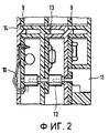
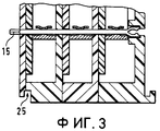
фиг. 2 - 3 - частичные поперечные разрезы через блок шинных клемм, в соответствии с фиг. 1;
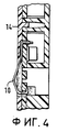
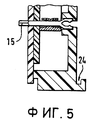
фиг. 4 - 5 - частичные поперечные разрезы через блок шинных клемм, в соответствии с фиг. 1;
фиг. 6 - детальное поперечное сечение к фиг. 2 и 4;
фиг. 7 - детальное изображение к фиг. 3 и 5.The drawings depict:
FIG. 1 is a perspective view of two bus terminal blocks;
FIG. 2 to 3 are partial cross-sectional views through a bus terminal block, in accordance with FIG. 1;
FIG. 4 to 5 are partial cross-sectional views through a bus terminal block, in accordance with FIG. 1;
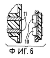
FIG. 6 is a detailed cross section to FIG. 2 and 4;
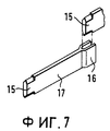
FIG. 7 is a detailed view of FIG. 3 and 5.
На фиг. 3 представлены два блока шинных клемм, в соответствии с изобретением, состоящие соответственно из трех отдельных клемм шины, в виде так называемых тройных модулей. In FIG. 3 shows two bus terminal blocks, in accordance with the invention, consisting respectively of three separate bus terminals, in the form of so-called triple modules.
Каждая отдельная шинная клемма имеет электронику ввода/вывода, встроенную в корпус 8 из изоляционного материала, которая на фиг. 1 видна в форме смонтированной печатной платы 9. Each individual bus terminal has an input / output electronics integrated in the housing 8 of insulating material, which in FIG. 1 is visible in the form of a mounted printed circuit board 9.
Каждая печатная плата 9 имеет шинные контакты, с которыми она соединена электрически, которые расположены на одной боковой поверхности шинных клемм в виде пружинящего нажимного пальца 10, а на противолежащей боковой поверхности шинных клемм - в виде жестко установленных контактных перемычек 11 (см. фиг. 2 и 4). Each printed circuit board 9 has bus contacts with which it is electrically connected, which are located on one side surface of the bus terminals in the form of a
На фиг. 6 контактные перемычки 11 можно увидеть на поперечном сечении сверху, а контактные пальцы 10 соответственно на противолежащей стороне соседней клеммы. In FIG. 6, the
В общей сложности представленные отдельные шинные клеммы (см. фиг. 4 и 5) и представленные блоки шинных клемм (см. фиг. 1, 2 и 3) имеют соответственно по шесть шинных контактов на каждой боковой поверхности своего корпуса, выполненного из изоляционного материала. In total, the presented individual bus terminals (see Figs. 4 and 5) and the presented bus terminal blocks (see Figs. 1, 2 and 3) each have six bus contacts on each side surface of their housing made of insulating material.
Это соответствует проводникам, интегрированным в шинные клеммы и пропущенным через них с образованием цикла, из которых два проводника предусмотрены для энергоснабжения электроники ввода/вывода на соответствующих печатных платах 9 шинных клемм, а оставшиеся четыре являются проводниками шины данных (у кольцевой топологии шины данных соответственно два проводника информационной шины в направлении "туда" и два - в направлении "обратно"). This corresponds to the conductors integrated into the bus terminals and passed through them with the formation of a cycle, of which two conductors are provided for power supply of the I / O electronics on the corresponding printed circuit boards 9 bus terminals, and the remaining four are conductors of the data bus (the ring topology of the data bus has two information bus conductor in the "there" direction and two in the "back" direction).
Прохождение этих проводников через блок шинных клемм, а также через отдельную шинную клемму хорошо видно на фиг. 2 и 4. The passage of these conductors through the bus terminal block as well as through the separate bus terminal is clearly seen in FIG. 2 and 4.
На блоке шинных клемм для этой цели предусмотрены штифтовые гнезда 12, так что дискообразные отдельные клеммы могут неипростейшим образом соединяться в любой двойной, тройной или прочий многократный модуль. On the bus terminal block,
Для этой цели предназначены мощные кнопочные фиксаторы 13 на корпусе из изоляционного материала. Замыкание каждой отдельной шинной клеммы и каждого блока клеммных шин образуют соответствующие замыкающие пластины 14 из изоляционного материала (см. фиг. 2 и 4).
Фиг. 3, 5 и 7 наглядно показывают конструкцию и расположение перемычек силового тока, состоящих соответственно из контактного ножа 15 и пружинящей контактной вилки 16, которые образуют наконечники пруткообразной плоской шины 17, проходящей через отдельную шинную клемму (фиг. 5) и через блок шинных клемм (фиг. 3). FIG. 3, 5 and 7 clearly show the design and location of the power current jumpers, consisting respectively of a
Как представлено на фиг. 1, перемычки для силового тока 15, 16 расположены на достаточном расстоянии от шинных контактов 10, 11, так как они служат снабжению силовым током абонентов, подключенных к местам, предназначенным для шинных клемм (приводов головок, сенсорных датчиков, приборов), и могут проводить значительно более высокий потенциал напряжения, чем шинные контакты. As shown in FIG. 1, jumpers for the
Места, где находятся клеммы, предназначенные для параллельного проводного соединения пользователей, доступны сверху, как это представлено на фиг. 1. The places where the terminals are intended for parallel wired users are accessible from above, as shown in FIG. 1.
В данном примере исполнения для каждого пользователя предусмотрен сигнальный вывод 18, вывод (+) 19, вывод (-) 20 и вывод защитного проводника 21. Каждое клеммное место выполнено известным способом в виде пружинящей клеммы 22 и не требует дальнейшего описания. In this embodiment, a signal output 18, output (+) 19, output (-) 20 and protective conductor output 21 is provided for each user. Each terminal location is made in a known manner in the form of a
Над сигнальным выводом предусмотрены светодиоды 23, которые индицируют статус ввод/вывод и при необходимости наличие неисправностей. LEDs 23 are provided above the signal output, which indicate I / O status and, if necessary, faults.
На фиг. 3 и 5, а также на фиг. 1 видно, что шинные клеммы имеют на своих боковых поверхностях взаимодействующие друг с другом выступы и углубления 24, 25, которые входят в зацепление друг с другом при насаживании и закреплении шинных клемм на несущей шине и соединяют шинные клеммы в направлении их последовательной установки с механической прочностью при растяжении. In FIG. 3 and 5, as well as in FIG. 1 it can be seen that the bus terminals have protrusions and
Claims (5)
Applications Claiming Priority (2)
| Application Number | Priority Date | Filing Date | Title |
|---|---|---|---|
| DE4402002A DE4402002B4 (en) | 1994-01-18 | 1994-01-18 | I / O modules / for a data bus |
| DEP4402002.3 | 1994-01-18 |
Publications (2)
| Publication Number | Publication Date |
|---|---|
| RU95100763A RU95100763A (en) | 1997-03-10 |
| RU2139615C1 true RU2139615C1 (en) | 1999-10-10 |
Family
ID=6508583
Family Applications (1)
| Application Number | Title | Priority Date | Filing Date |
|---|---|---|---|
| RU95100763A RU2139615C1 (en) | 1994-01-18 | 1995-01-17 | Input/output module for data bus |
Country Status (9)
| Country | Link |
|---|---|
| US (1) | US5716241A (en) |
| JP (1) | JP3579803B2 (en) |
| KR (1) | KR100379665B1 (en) |
| CN (1) | CN1103073C (en) |
| DE (1) | DE4402002B4 (en) |
| FR (1) | FR2715239B1 (en) |
| GB (1) | GB2286086B (en) |
| RU (1) | RU2139615C1 (en) |
| TW (1) | TW275722B (en) |
Cited By (4)
| Publication number | Priority date | Publication date | Assignee | Title |
|---|---|---|---|---|
| RU2477911C1 (en) * | 2011-11-15 | 2013-03-20 | Общество с ограниченной ответственностью "ТРЭИ ГМБХ" | Input-output module for data bus |
| RU2485728C2 (en) * | 2008-12-24 | 2013-06-20 | Сажем Дефанс Секюрите | Electrical unit with individual power control modules |
| RU2519909C2 (en) * | 2009-12-08 | 2014-06-20 | Абб Текнолоджи Аг | Input/output module |
| RU2638152C2 (en) * | 2012-11-30 | 2017-12-12 | Абб Аг | Connecting terminal |
Families Citing this family (119)
| Publication number | Priority date | Publication date | Assignee | Title |
|---|---|---|---|---|
| DE4410301C2 (en) * | 1994-03-25 | 1999-07-29 | Phoenix Contact Gmbh & Co | Electrical terminal block |
| KR19990044570A (en) * | 1995-09-13 | 1999-06-25 | 세이취크 제이 엘 | Mounting and electrical connection system for stackable electronic modules |
| FR2739979B1 (en) * | 1995-10-16 | 1997-12-05 | Schneider Electric Sa | ELECTRICAL TERMINAL |
| FR2739978B1 (en) * | 1995-10-16 | 1997-12-05 | Schneider Electric Sa | ELECTRICAL TERMINAL |
| DE19648351A1 (en) * | 1996-11-22 | 1998-05-28 | Wieland Electric Gmbh | Decentralized input / output module for a data bus |
| DE29620407U1 (en) * | 1996-11-22 | 1998-01-02 | Siemens Ag | Device for coding plug-in modules and device for connecting external lines with such a coding device |
| DE19650989C2 (en) * | 1996-11-28 | 2003-06-26 | Wago Verwaltungs Gmbh | Terminal block with side bridging contacts |
| DE19650988C2 (en) * | 1996-11-28 | 2003-06-26 | Wago Verwaltungs Gmbh | Terminal block with built-in or pluggable electronics |
| DE19710768C2 (en) * | 1997-03-16 | 1999-11-11 | Phoenix Contact Gmbh & Co | Electrical or electronic device |
| DE19718996C1 (en) * | 1997-05-06 | 1998-06-04 | Phoenix Contact Gmbh & Co | Module for rail mounted electronic module for data and energy bus lines |
| EP0896504B2 (en) * | 1997-08-05 | 2008-03-12 | Phoenix Contact GmbH & Co. KG | Electrical or electronic apparatus |
| DE19748429A1 (en) | 1997-11-03 | 1999-05-06 | Siemens Ag | Switchgear unit capable of communication |
| DE19748530B9 (en) * | 1997-11-03 | 2004-09-09 | Siemens Ag | Modular automation device and assembly of a modular automation device |
| DE19748531A1 (en) | 1997-11-03 | 1999-05-06 | Siemens Ag | Assembly system for load feeders with permanent wiring |
| FR2771223B1 (en) * | 1997-11-19 | 2000-01-14 | Entrelec Sa | INTERFACE DEVICE BETWEEN EQUIPMENT OF A SYSTEM |
| DE29720511U1 (en) * | 1997-11-19 | 1998-01-08 | Weidmueller Interface | Installation housing for printed circuit boards and electronic components |
| US6172875B1 (en) * | 1998-11-17 | 2001-01-09 | Rockwell Technologies, Llc | Programmable logic controller module assembly and locking system |
| USD428600S (en) * | 1999-02-15 | 2000-07-25 | Yamatake Corporation | I/O (input/output) module |
| JP3459375B2 (en) * | 1999-04-06 | 2003-10-20 | 矢崎総業株式会社 | Crimp joint connector |
| WO2000062375A1 (en) * | 1999-04-14 | 2000-10-19 | The Whitaker Corporation | Electrical terminal for an input-output module |
| JP3388718B2 (en) * | 1999-08-03 | 2003-03-24 | エスエムシー株式会社 | Serial-parallel signal conversion input / output device |
| JP3130021B1 (en) * | 1999-08-06 | 2001-01-31 | 盟友技研株式会社 | Relay connection device |
| US6425770B1 (en) | 2000-04-14 | 2002-07-30 | Rockwell Automation Technologies, Inc. | Input/output device having removable module |
| DE10040651B4 (en) * | 2000-08-19 | 2004-02-05 | Erni Elektroapparate Gmbh | Electronic device with data and / or power bus connection |
| JP2004509471A (en) * | 2000-09-12 | 2004-03-25 | タイコ エレクトロニクス アンプ ゲゼルシャフト ミット ベシュレンクテル ハウツンク | Modular connection structure for Ethernet in the industrial sector |
| US6572403B2 (en) | 2001-01-22 | 2003-06-03 | National Instruments Corporation | Expansion plug apparatus for connecting a plurality of terminal blocks |
| ATE300107T1 (en) * | 2001-05-16 | 2005-08-15 | Gustav Hensel Gmbh & Co Kg | SWITCHGEAR SYSTEM |
| DE20120690U1 (en) * | 2001-12-20 | 2003-02-13 | Weidmueller Interface | Terminal block with circuit board |
| DE20208041U1 (en) * | 2002-05-21 | 2003-10-02 | Weidmueller Interface | Module order and adapter module |
| DE10251004B4 (en) * | 2002-11-02 | 2014-04-10 | Abb Ag | Bus-capable connection and control device for decentralized use in low-voltage consumer installations |
| DE10351479B4 (en) * | 2002-11-08 | 2012-05-10 | E. Dold & Söhne KG | Device system with electrical equipment mounted on a mounting rail and BUS cable |
| DE10301003B3 (en) * | 2003-01-13 | 2004-09-30 | Siemens Ag | Modular installation device |
| GB0312414D0 (en) * | 2003-05-30 | 2003-07-02 | Fortress Interlocks Ltd | Security or safety bus system |
| DE20315837U1 (en) * | 2003-10-15 | 2005-03-03 | Weidmüller Interface GmbH & Co. KG | Distributor for connecting electrical equipment with multiple power supply |
| DE20315838U1 (en) * | 2003-10-15 | 2005-02-24 | Weidmüller Interface GmbH & Co. KG | Distributor for connecting electrical devices with lighting device |
| KR100662187B1 (en) * | 2004-03-15 | 2006-12-27 | 오므론 가부시키가이샤 | Sensor controller |
| US7865326B2 (en) | 2004-04-20 | 2011-01-04 | National Instruments Corporation | Compact input measurement module |
| DE102005028735B4 (en) * | 2005-06-20 | 2008-07-24 | Wago Verwaltungsgesellschaft Mbh | Monitoring and control device and bridge module for this |
| DE102006019160B4 (en) * | 2006-04-21 | 2008-02-28 | Phoenix Contact Gmbh & Co. Kg | Connector with short-circuit contacts |
| DE102006023660C5 (en) * | 2006-05-18 | 2013-01-10 | Phoenix Contact Gmbh & Co. Kg | Electrical or electronic device |
| DE102007004865B4 (en) * | 2007-01-31 | 2010-07-01 | Tyco Electronics Amp Gmbh | Rail-based, modular device system of industrial information network technology |
| DE102007006830B8 (en) | 2007-02-07 | 2009-12-24 | Phoenix Contact Gmbh & Co. Kg | Control and / or data transmission module |
| ATE468551T1 (en) | 2007-06-26 | 2010-06-15 | Siemens Ag | PERIPHERAL MODULE AND PERIPHERAL SYSTEM FOR AN AUTOMATION SYSTEM |
| EP2037537A1 (en) * | 2007-09-11 | 2009-03-18 | HaWi Energietechnik AG | Connection module, accumulator module and subassembly consisting thereof for a pre-accumulator for a photovoltaic facility |
| DE102007054678B3 (en) * | 2007-11-14 | 2009-04-02 | Wago Verwaltungsgesellschaft Mbh | Method for detecting sources of interference for automation equipment and interference source detection unit for this purpose |
| DE102008007145A1 (en) * | 2008-01-31 | 2009-08-27 | Wieland Electric Gmbh | Current injection device |
| DE102008039864B4 (en) | 2008-08-27 | 2011-01-05 | Wago Verwaltungsgesellschaft Mbh | clamping device |
| DE102008058090B4 (en) * | 2008-11-18 | 2021-08-26 | Abb Ag | Input / output module for an automation device |
| JP5289067B2 (en) * | 2009-01-06 | 2013-09-11 | 三菱電機株式会社 | Signal repeater |
| DE102009015508B4 (en) | 2009-04-02 | 2015-06-18 | Phoenix Contact Gmbh & Co. Kg | Connection system for control modules |
| JP5248398B2 (en) * | 2009-04-07 | 2013-07-31 | 富士通コンポーネント株式会社 | connector |
| DE202010004408U1 (en) | 2009-12-10 | 2011-04-21 | Weidmüller Interface GmbH & Co. KG | Sequence of connection modules |
| DE102009059011A1 (en) * | 2009-12-17 | 2011-06-22 | Phoenix Contact GmbH & Co. KG, 32825 | Connection system for connecting a single-row housing with a connection element |
| EP2369790B1 (en) | 2010-03-24 | 2015-07-29 | WAGO Kontakttechnik GmbH & Co. KG | Communication device |
| WO2011120881A1 (en) | 2010-03-31 | 2011-10-06 | Weidmüller Interface GmbH & Co. KG | Connection module being capable of serving as a bus |
| DE202010005979U1 (en) | 2010-04-22 | 2011-08-26 | Weidmüller Interface GmbH & Co. KG | Bus-capable, connectable connection module |
| DE202010006065U1 (en) | 2010-04-23 | 2010-08-05 | VIPA Gesellschaft für Visualisierung und Prozeßautomatisierung m.b.H. | Sequentially buildable, modular bus for an automation or control system |
| DE202010006140U1 (en) | 2010-04-28 | 2011-09-07 | Weidmüller Interface GmbH & Co. KG | Bus-capable connection module |
| DE102010019022A1 (en) * | 2010-05-03 | 2011-11-03 | Siemens Aktiengesellschaft | Clamping arrangement for an electrical device |
| DE202011000835U1 (en) | 2010-06-29 | 2011-11-08 | Weidmüller Interface GmbH & Co. KG | Bus-capable connection and / or function module and connection system with such modules |
| DE102011051154A1 (en) | 2010-08-02 | 2012-02-02 | Weidmüller Interface GmbH & Co. KG | Bus-compatible, alignable connection and/or function module for controlling and/or supervision of technical processes of soldering machine for e.g. industrial automation, has connection and/or functional unit provided with function modules |
| US9055688B2 (en) * | 2010-08-20 | 2015-06-09 | Rockwell Automation Technologies, Inc. | Input/output circuits having status indicators aligned with respective terminals |
| US8579639B2 (en) * | 2010-08-20 | 2013-11-12 | Rockwell Automation Technologies, Inc. | Systems and methods for coupling input/output devices |
| DE202010013453U1 (en) | 2010-09-23 | 2010-11-25 | Wago Verwaltungsgesellschaft Mbh | Rest module |
| SE535236C2 (en) * | 2010-10-22 | 2012-06-05 | Alfa Laval Corp Ab | Heat exchanger plate and plate heat exchanger |
| EP2515380B1 (en) * | 2011-04-19 | 2016-05-25 | Pepperl + Fuchs GmbH | Field devices for improved safety |
| DE102011050364B4 (en) | 2011-05-13 | 2013-08-29 | Tyco Electronics Amp Gmbh | Plug contact element and plug contact arrangement for the transmission of frequencies in the gigahertz range |
| DE102011052964B4 (en) | 2011-08-24 | 2019-01-31 | Phoenix Contact Gmbh & Co. Kg | Electrical contact element for cross-routing between I / O modules |
| DE202011105337U1 (en) | 2011-09-06 | 2011-11-21 | Systeme Helmholz Gmbh | Device for the electrical and mechanical connection of modules of a modular automation system |
| US8668518B2 (en) * | 2012-03-12 | 2014-03-11 | Dinkle Enterprise Co., Ltd. | Data bus structure for terminal blocks and terminal blocks using the same |
| DE102012204026B4 (en) | 2012-03-14 | 2016-02-18 | Dinkle Enterprise Co., Ltd. | Data bus structure for terminal blocks, terminal blocks using them, and arrangement of such a data bus structure |
| USD732535S1 (en) * | 2012-06-25 | 2015-06-23 | Wago Verwaltungsgesellschaft Mbh | Industrial enclosure |
| DE102012110698B3 (en) * | 2012-11-08 | 2014-02-27 | Pilz Gmbh & Co. Kg | Device for controlling and / or regulating a technical installation |
| DE102013206147B4 (en) | 2013-04-08 | 2022-06-09 | Beckhoff Automation Gmbh | Dongle module and automation system |
| CN103337744B (en) * | 2013-07-10 | 2016-06-01 | 迈柯唯医疗设备(苏州)有限公司 | Integrated form inserts weak electrical connection module soon |
| DE102013022579B3 (en) | 2013-10-21 | 2020-06-04 | Wago Verwaltungsgesellschaft Mbh | Electronics module |
| DE102013111578B4 (en) | 2013-10-21 | 2019-04-18 | Wago Verwaltungsgesellschaft Mbh | electronic module |
| DE102013111571B4 (en) | 2013-10-21 | 2016-11-17 | Wago Verwaltungsgesellschaft Mbh | Device housing, electronic devices and plug-in contact carrier |
| DE102013111551B3 (en) | 2013-10-21 | 2015-01-22 | Wago Verwaltungsgesellschaft Mbh | DIN rail enclosure |
| DE102013112099B4 (en) * | 2013-11-04 | 2021-10-07 | Phoenix Contact Gmbh & Co. Kg | Component assembly system |
| DE102013112101B4 (en) * | 2013-11-04 | 2018-05-09 | Phoenix Contact Gmbh & Co. Kg | Components Mounting System |
| DE102013112117A1 (en) | 2013-11-04 | 2015-05-07 | Phoenix Contact Gmbh & Co. Kg | Functional component for a component assembly system |
| DE102013112115A1 (en) * | 2013-11-04 | 2015-05-07 | Phoenix Contact Gmbh & Co. Kg | Bridge module for a component assembly system |
| SG2013094396A (en) * | 2013-12-19 | 2015-07-30 | Rockwell Automation Asia Pacific Business Ctr Pte Ltd | Slice-io housing with side ventilation |
| DE102014103575A1 (en) * | 2014-03-17 | 2015-09-17 | Obo Bettermann Gmbh & Co. Kg | Device for protection against overvoltages |
| KR101562341B1 (en) * | 2014-04-18 | 2015-10-22 | 주식회사 크래비스 | Optical-coupled bus input/output apparatus and input/output module included in the apparatus |
| DE102014111030B4 (en) | 2014-08-04 | 2017-02-09 | Beckhoff Automation Gmbh | Coupling unit and industrial control system |
| DE102014111031A1 (en) | 2014-08-04 | 2016-02-04 | Beckhoff Automation Gmbh | Module, coupling unit, and control system |
| TWI610505B (en) | 2015-05-13 | 2018-01-01 | 町洋企業股份有限公司 | Connector module |
| US9864352B2 (en) | 2015-06-01 | 2018-01-09 | Rockwell Automation Asia Pacific Business Ctr. Pte., Ltd. | Slice I/O—field power bus breaker |
| JP6784483B2 (en) * | 2015-07-24 | 2020-11-11 | 東朋テクノロジー株式会社 | Sensor terminal block and terminal block unit |
| TWI559630B (en) * | 2015-08-04 | 2016-11-21 | 町洋企業股份有限公司 | Connector Module |
| CN106469876B (en) * | 2015-08-17 | 2018-11-23 | 町洋企业股份有限公司 | Connector modules |
| US9583849B1 (en) * | 2015-09-16 | 2017-02-28 | Dinkle Enterprise Co., Ltd. | Connector module with multiple connection modes |
| KR101734861B1 (en) * | 2015-12-29 | 2017-05-12 | (주)메티스 | Remote I/O apparatus based on CC-LINK |
| TWI597907B (en) | 2016-04-28 | 2017-09-01 | 町洋企業股份有限公司 | Connector Module and Connecting Blade Thereof |
| DE102016108321A1 (en) * | 2016-05-04 | 2017-11-09 | Beckhoff Automation Gmbh | Electronic terminal block for a data bus |
| DE102016122263A1 (en) * | 2016-11-18 | 2018-05-24 | Phoenix Contact Gmbh & Co. Kg | Shunting connector and method for producing a jumper connector |
| KR101928381B1 (en) | 2016-11-29 | 2018-12-12 | 주식회사 크래비스 | Controller of industrial machines |
| EP3439113B1 (en) * | 2017-02-16 | 2022-06-08 | Fuji Electric FA Components & Systems Co., Ltd. | Lead wire terminal block and electric device connection socket including the same |
| DE102017103843B4 (en) * | 2017-02-24 | 2018-11-15 | Lisa Dräxlmaier GmbH | Fixing element for a power interface, power interface and carrier equipped therewith |
| CN109326903B (en) * | 2017-07-31 | 2020-08-04 | 四零四科技股份有限公司 | Industrial input/output device with series connector |
| US10205258B1 (en) * | 2017-10-25 | 2019-02-12 | Moxa Inc. | Industrial input and output device with series connectors |
| DE202018100964U1 (en) * | 2018-02-21 | 2019-05-23 | Weidmüller Interface GmbH & Co. KG | Contact and busbar arrangement |
| TWI697161B (en) * | 2018-03-09 | 2020-06-21 | 町洋企業股份有限公司 | System comprising multiple functional modules and addressing method for functional modules thereof |
| TWI670586B (en) * | 2018-08-27 | 2019-09-01 | 四零四科技股份有限公司 | Industrial input/output device with movable connector |
| FR3086108B1 (en) * | 2018-09-19 | 2020-08-28 | Radiall Sa | MINIATURE LOW STEP HYPERFREQUENCY COAXIAL CONNECTOR, INTENDED IN PARTICULAR FOR CONNECTING TWO PRINTED CIRCUIT BOARDS BETWEEN THEM |
| JP6962309B2 (en) * | 2018-12-14 | 2021-11-05 | オムロン株式会社 | Terminal block and terminal block set |
| JP7001047B2 (en) * | 2018-12-14 | 2022-01-19 | オムロン株式会社 | Terminal block |
| DE102018133646A1 (en) | 2018-12-28 | 2020-07-02 | Beckhoff Automation Gmbh | Basic module and function module for a control cabinet system |
| DE102018133657A1 (en) | 2018-12-28 | 2020-07-02 | Beckhoff Automation Gmbh | BASIC MODULE AND FUNCTIONAL MODULE FOR A CONTROL CABINET SYSTEM AND CONTROL CABINET SYSTEM |
| DE102018133647A1 (en) * | 2018-12-28 | 2020-07-02 | Beckhoff Automation Gmbh | Control cabinet system consisting of basic module and function modules as well as function module |
| US10716235B1 (en) * | 2019-02-01 | 2020-07-14 | Cisco Technology, Inc. | Adjustable mounting rail latches |
| DE202019101037U1 (en) * | 2019-02-22 | 2020-05-25 | WAGO Verwaltungsgesellschaft mit beschränkter Haftung | Terminal block for defining a terminal block arrangement on a mounting rail |
| DE102019106082B4 (en) | 2019-03-11 | 2021-06-24 | Beckhoff Automation Gmbh | CABINET SYSTEM WITH SEAL INSERT |
| TWI709307B (en) * | 2019-04-15 | 2020-11-01 | 町洋企業股份有限公司 | Control system comprising multiple functional modules and addressing method for functional modules thereof |
| DE102020202081A1 (en) | 2020-02-19 | 2021-08-19 | Robert Bosch Gesellschaft mit beschränkter Haftung | MODULAR INDUSTRIAL CONTROL AND METHOD FOR MANUFACTURING A MODULAR INDUSTRIAL CONTROL |
| KR102469069B1 (en) * | 2020-07-22 | 2022-11-22 | 주식회사 엠투아이코퍼레이션 | Remote input/output apparatus |
| US11832377B2 (en) | 2021-09-22 | 2023-11-28 | Rockwell Automation Asia Pacific Business Center Pte. Ltd. | Industrial control device and method for insertion and removal of a module under power without interruption |
Family Cites Families (22)
| Publication number | Priority date | Publication date | Assignee | Title |
|---|---|---|---|---|
| DE746124C (en) * | 1940-08-17 | 1944-12-15 | Messerschmitt A G | Quick disconnection point for electrical lines on aircraft |
| DE1047284B (en) * | 1955-12-21 | 1958-12-24 | Werner Soehnchen | Terminal block made of elastic material |
| DE2205086A1 (en) * | 1972-02-03 | 1973-08-16 | Controlmatic Ges Fuer Ind Auto | TERMINAL BLOCK SYSTEM |
| DE2236347C3 (en) * | 1972-07-25 | 1975-12-11 | Robert Bosch Gmbh, 7000 Stuttgart | Plug-in base for contacting and fastening electrical components |
| US4184733A (en) * | 1978-07-24 | 1980-01-22 | Square D Company | Segmented fanning strip |
| DE2843858A1 (en) * | 1978-10-07 | 1980-04-17 | Bbc Brown Boveri & Cie | BUSBAR SYSTEM FOR CONNECTING ELECTRICAL INSTALLATION EQUIPMENT |
| DE3030070C1 (en) * | 1980-08-08 | 1982-06-16 | Phönix Elektrizitätsgesellschaft H. Knümann GmbH & Co KG, 4933 Blomberg | Electrical connection terminal |
| FR2588438B1 (en) * | 1985-10-09 | 1989-05-05 | Telemecanique Electrique | DEVICE FOR ASSEMBLING MODULAR BLOCKS OF ELECTRICAL EQUIPMENT |
| DE3571177D1 (en) * | 1985-11-09 | 1989-07-27 | Weidmueller C A Gmbh Co | INITIATOR TERMINAL BLOCK |
| EP0222038B1 (en) * | 1985-11-13 | 1989-05-10 | C.A. Weidmüller GmbH & Co. | Terminals for side-by-side mounting |
| FR2625603B1 (en) * | 1987-12-30 | 1993-05-07 | Telemecanique Electrique | PROTECTED ELECTRIC SWITCHING APPARATUS AND FIXING DEVICE THEREOF |
| DE3805158A1 (en) * | 1988-02-15 | 1989-08-24 | Wago Verwaltungs Gmbh | SERIES TERMINAL FOR THE TWO-WIRE POWER SUPPLY OF ELECTRICAL OR ELECTRONIC COMPONENTS, IN PARTICULAR INITIATORS |
| EP0364618B1 (en) * | 1988-10-18 | 1993-10-13 | Weidmüller Interface GmbH & Co. | Multiple signal transmission device |
| JPH02210776A (en) * | 1989-02-09 | 1990-08-22 | Seiko Kiki Seisakusho:Kk | Unit type terminal board |
| DE4020791C1 (en) * | 1990-06-28 | 1991-06-06 | Mannesmann Ag, 4000 Duesseldorf, De | |
| EP0499660B1 (en) * | 1991-02-18 | 1995-04-19 | Siemens Aktiengesellschaft | Device for coupling electrical terminals |
| JPH04264609A (en) * | 1991-02-19 | 1992-09-21 | Fujitsu Ltd | Inter-package connection system |
| JPH05127776A (en) * | 1991-11-01 | 1993-05-25 | Nec Corp | Method and device for wiring connection between cards |
| US5186661A (en) * | 1992-04-03 | 1993-02-16 | Amp Incorporated | Lid with integral hinges |
| DE4231625C2 (en) * | 1992-09-22 | 1995-05-24 | Phoenix Contact Gmbh & Co | Busbar arrangement |
| JPH077040B2 (en) * | 1992-12-07 | 1995-01-30 | 山一電機株式会社 | Socket for electrical parts |
| DE4303717C2 (en) * | 1993-02-09 | 1996-02-08 | Phoenix Contact Gmbh & Co | Module for connecting electrical lines and for processing and / or processing electrical signals |
-
1994
- 1994-01-18 DE DE4402002A patent/DE4402002B4/en not_active Expired - Lifetime
- 1994-12-15 GB GB9425301A patent/GB2286086B/en not_active Expired - Lifetime
- 1994-12-17 TW TW083111807A patent/TW275722B/zh not_active IP Right Cessation
-
1995
- 1995-01-06 FR FR9500088A patent/FR2715239B1/en not_active Expired - Fee Related
- 1995-01-10 KR KR1019950000294A patent/KR100379665B1/en not_active IP Right Cessation
- 1995-01-13 JP JP03474895A patent/JP3579803B2/en not_active Expired - Fee Related
- 1995-01-17 RU RU95100763A patent/RU2139615C1/en not_active IP Right Cessation
- 1995-01-18 CN CN95100248A patent/CN1103073C/en not_active Expired - Lifetime
- 1995-01-18 US US08/374,312 patent/US5716241A/en not_active Expired - Lifetime
Non-Patent Citations (1)
| Title |
|---|
| 1. Проспект фирмы SIEMENS "Die grossen Sparer-das System KOALA", 1993. 2. * |
Cited By (4)
| Publication number | Priority date | Publication date | Assignee | Title |
|---|---|---|---|---|
| RU2485728C2 (en) * | 2008-12-24 | 2013-06-20 | Сажем Дефанс Секюрите | Electrical unit with individual power control modules |
| RU2519909C2 (en) * | 2009-12-08 | 2014-06-20 | Абб Текнолоджи Аг | Input/output module |
| RU2477911C1 (en) * | 2011-11-15 | 2013-03-20 | Общество с ограниченной ответственностью "ТРЭИ ГМБХ" | Input-output module for data bus |
| RU2638152C2 (en) * | 2012-11-30 | 2017-12-12 | Абб Аг | Connecting terminal |
Also Published As
| Publication number | Publication date |
|---|---|
| CN1118465A (en) | 1996-03-13 |
| GB2286086B (en) | 1997-12-24 |
| GB9425301D0 (en) | 1995-02-15 |
| FR2715239B1 (en) | 1997-05-09 |
| TW275722B (en) | 1996-05-11 |
| JP3579803B2 (en) | 2004-10-20 |
| KR100379665B1 (en) | 2003-06-02 |
| JPH07261875A (en) | 1995-10-13 |
| DE4402002B4 (en) | 2005-10-27 |
| FR2715239A1 (en) | 1995-07-21 |
| CN1103073C (en) | 2003-03-12 |
| DE4402002A1 (en) | 1995-07-20 |
| RU95100763A (en) | 1997-03-10 |
| KR950033779A (en) | 1995-12-26 |
| US5716241A (en) | 1998-02-10 |
| GB2286086A (en) | 1995-08-02 |
Similar Documents
| Publication | Publication Date | Title |
|---|---|---|
| RU2139615C1 (en) | Input/output module for data bus | |
| JP4440111B2 (en) | Network connection sensor assembly | |
| US7566234B2 (en) | Connector apparatus with code means | |
| ATE241861T1 (en) | ELECTRICAL CLAMP CONNECTION DEVICE | |
| EP0434964A1 (en) | A set of assembly elements intended to facilitate concurrent electrical connection of a plurality of modular automatic circuit breakers | |
| DE69517854D1 (en) | Electrical connector for current conductors | |
| US20080173479A1 (en) | Modular method and system for insulated bus bar cable harness termination concept | |
| US5928008A (en) | Earthing module | |
| US5326933A (en) | Electrical installation system | |
| DE59304412D1 (en) | Screwless connection terminal for electrical conductors | |
| US7140926B2 (en) | Telecommunications terminal module | |
| JP4268782B2 (en) | Distribution board with breaker terminal block and primary feed breaker | |
| FI104036B (en) | Connecting strip for incoming and outgoing electrical wiring | |
| JPH09190849A (en) | Multiple connection module for cable connection, of main distributing part of communication lead wire and data lead wire | |
| JPH05242941A (en) | Lead line array connector | |
| TW429725B (en) | Modular multiple terminal strip for solder-free IDC wiring of insulated electrical conductors | |
| EP0613214B1 (en) | Terminal table for electrical equipment and power converting device employing the same | |
| DE59913815D1 (en) | Multi-phase current busbar | |
| KR200146721Y1 (en) | Connector terminal | |
| US11575221B2 (en) | Junction box | |
| CN210744370U (en) | Terminal interface device for distribution module and rail type terminal bus trunk body | |
| JP4607363B2 (en) | Distribution board primary breaker connection structure for distribution board | |
| JPH0758459A (en) | Connection structure of signaling device | |
| SU1725298A1 (en) | Coaxial cable connection unit to radio equipment | |
| CN110797722A (en) | Terminal interface device for distribution module and rail type terminal bus trunk body |
Legal Events
| Date | Code | Title | Description |
|---|---|---|---|
| MM4A | The patent is invalid due to non-payment of fees |
Effective date: 20140118 |