RU2139019C1 - Device for implantation of flexible artificial lens of eye - Google Patents
Device for implantation of flexible artificial lens of eye Download PDFInfo
- Publication number
- RU2139019C1 RU2139019C1 RU98107786A RU98107786A RU2139019C1 RU 2139019 C1 RU2139019 C1 RU 2139019C1 RU 98107786 A RU98107786 A RU 98107786A RU 98107786 A RU98107786 A RU 98107786A RU 2139019 C1 RU2139019 C1 RU 2139019C1
- Authority
- RU
- Russia
- Prior art keywords
- piston
- nozzle
- attachment
- working part
- section
- Prior art date
Links
Images



Landscapes
- Prostheses (AREA)
Abstract
Description
Изобретение относится к медицинской технике, а именно к офтальмохирургическим инструментам. The invention relates to medical equipment, namely to ophthalmic surgical instruments.
Известно устройство для имплантации гибких искусственных хрусталиков глаза (ИХГ), содержащее корпус в виде полого цилиндра с направляющей трубкой, ложем для ИХГ и поршнем, снабженным насадкой (PCT WO 89/10729 A1/Arcofil S.A./, 16.11.89, A 61 F 2/16). A device for implantation of flexible artificial eye lenses (IHG), comprising a body in the form of a hollow cylinder with a guide tube, a bed for IHG and a piston equipped with a nozzle (PCT WO 89/10729 A1 / Arcofil SA /, 16.11.89, A 61 F 2 /16).
Недостатками данного устройства являются сложность конструктивного решения, то, что оно состоит из нескольких сборных частей (ложе хрусталика и направляющая трубка). В процессе имплантации могут возникать препятствия, мешающие плавному продвижению ИХГ. В процессе проталкивания в рабочую часть ИХГ могут происходить повреждения покрытий и гаптической части ИХГ вплоть до разрыва последней поршнем. The disadvantages of this device are the complexity of the design solution, the fact that it consists of several prefabricated parts (the bed of the lens and the guide tube). In the process of implantation, obstacles may arise that interfere with the smooth progress of IHG. In the process of pushing into the working part of the IHG, damage to the coatings and the haptic part of the IHG can occur up to the rupture of the last piston.
Задачей изобретения является возможность осуществления имплантации гибких искусственных хрусталиков глаза через малый разрез (3,2 мм) для факоэмульсификации. The objective of the invention is the possibility of implantation of flexible artificial lenses through a small incision (3.2 mm) for phacoemulsification.
Техническим результатом является уменьшение травматизации покрытия и гаптической части ИХГ. The technical result is to reduce the trauma of the coating and the haptic part of the IHG.
Технический результат согласно изобретению достигается тем, что в устройстве для имплантации гибких искусственных хрусталиков глаза корпус устройства в основании выполнен в виде полого цилиндра с сечением в виде овала, плавно переходящего в сужающийся конус и затем в рабочую часть в виде полого цилиндра, при этом поршень со штоком выполнен как единое целое, а на рабочей части поршня, снабженного кольцевым пазом, установлена насадка, имеющая кольцевой выступ для фиксации в пазу поршня с возможностью продольного смещения поршня относительно насадки, причем диаметр рабочей части поршня равен внутреннему диаметру рабочей части корпуса, а сечение насадки соответствует внутреннему сечению основания корпуса, и тем, что насадка выполнена в виде концентрических деталей, вложенных друг в друга и с возможностью продольного смещения каждой относительно другой по принципу телескопической антенны, причем каждая деталь насадки на своей внешней боковой поверхности имеет кольцевой паз, а на внутренней боковой поверхности имеет кольцевой выступ для фиксации друг в друге. The technical result according to the invention is achieved by the fact that in the device for implantation of flexible artificial lenses of the eye, the body of the device at the base is made in the form of a hollow cylinder with a cross section in the form of an oval, smoothly turning into a tapering cone and then into the working part in the form of a hollow cylinder, the rod is made as a whole, and on the working part of the piston equipped with an annular groove, a nozzle is installed having an annular protrusion for fixing in the piston groove with the possibility of longitudinal displacement of the piston relative the nozzle, and the diameter of the working part of the piston is equal to the inner diameter of the working part of the housing, and the nozzle section corresponds to the internal section of the base of the housing, and the fact that the nozzle is made in the form of concentric parts embedded in each other and with the possibility of longitudinal displacement of each relative to the other according to the telescopic principle antenna, and each part of the nozzle on its outer side surface has an annular groove, and on the inner side surface has an annular protrusion for fixing in each other.
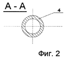
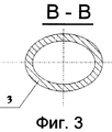
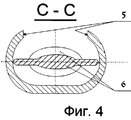
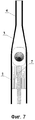
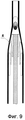
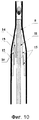
Сущность заявляемого технического решения поясняется чертежами. На фиг. 1. изображен общий вид устройства для имплантации гибких ИХГ в исходном состоянии с линзой. На фиг. 2, 3, 4, 5 представлены сечения устройства, а на фиг. 6. - фрагмент рабочий части поршня. На фиг. 7. показано устройство в исходном состоянии, а на фиг. 8, 9, 10 - в процессе имплантации. The essence of the proposed technical solution is illustrated by drawings. In FIG. 1. shows a General view of a device for implantation of flexible IHG in the initial state with a lens. In FIG. 2, 3, 4, 5 are sections of the device, and in FIG. 6. - a fragment of the working part of the piston. In FIG. 7. shows the device in its initial state, and in FIG. 8, 9, 10 - in the process of implantation.
Устройство для имплантации гибких искусственных хрусталиков глаза состоит из корпуса 1, имеющего основание 2, выполненное в виде полого цилиндра с сечением в виде овала, конической части 3 и рабочей части 4. В основании 2 выполнено отверстие 5 для помещения ИХГ 6 в устройство. В корпусе 1 расположен поршень с рабочей частью 7, снабженной кольцевым пазом 8, штоком 9 и ручкой в виде кольца 10, выполненный как единое целое. Рабочая часть 7 поршня снабжена насадкой, имеющей кольцевой выступ 11 и выполненной в виде нескольких деталей (12, 13, 14), вложенных одна в другую с выступами 15 на внутренних поверхностях деталей 12, 13 и пазами 16 на внешних поверхностях деталей 13, 14. Выступы и пазы рассчитаны таким образом, что сила смещения детали 13 насадки относительно детали 12 меньше силы, смещающей деталь 14 относительно детали 13, которая в свою очередь меньше силы, смещающей рабочую часть 7 поршня относительно детали 14. Корпус в своем основании имеет кольцевые ручки 17. Все детали устройства выполнены из пластмассы. The device for implantation of flexible artificial lenses of the eye consists of a body 1 having a
Устройство работает следующим образом. В отверстие 5 на корпусе 1 устройства помещают гибкий ИХГ 6, предварительно смоченный вискоэластическим материалом (HealoN, Визитил). Затем начинают осуществлять давление на шток 9, которое через рабочую часть 7 поршня насадку передается ИХГ 6, который под действием давления начинает смещаться в коническую часть 3 корпуса 1, при этом происходит его деформация соответственно форме данного участка конической части. Когда насадка поршня доходит до конической части, внешняя часть насадки (деталь 12), диаметр которой больше диаметра основания конической части 3, фиксируется в точке А (фиг. 8), а рабочая часть 7 поршня с оставшейся насадкой (детали 13 и 14) продолжает смещаться в коническую часть корпуса, продолжая смещать ИХГ по направлению к рабочей части 4. Когда рабочая часть 7 поршня с насадкой достигает места, где наружный диаметр детали 13 насадки больше диаметра конической части 3 (точка В фиг. 9.), деталь 13 остается на месте, а рабочая часть 7 поршня с деталью 14 насадки продолжает поступательное движение до тех пор, пока ИХГ 6 не окажется полностью в рабочей части 4 устройства. У основания рабочей части 4 устройства поступательное движение детали 14 насадки прекращается, так как внешний ее диаметр больше основания рабочей части 4, и дальнейшее продвижение ИХГ 6 по рабочей части 4 осуществляется за счет рабочей части 7 поршня. После этого рабочую часть 4 корпуса 1 вводят через склеральный тоннельный разрез в переднюю камеру глаза и направляют к месту имплантации. Затем, медленно надавливая на поршень, выдавливают ИХГ в место его имплантации. The device operates as follows. A
Использование предлагаемого устройства позволяет снизить частоту повреждений покрытий и гаптической части искусственных хрусталиков, снизив тем самым операционные и послеоперационные осложнения. Так как все детали устройства выполнены из пластмассы и технологически просты в исполнении, оно может быть использовано как одноразовое. Using the proposed device can reduce the frequency of damage to coatings and the haptic part of artificial lenses, thereby reducing surgical and postoperative complications. Since all parts of the device are made of plastic and are technologically simple to implement, it can be used as a disposable one.
Claims (2)
Priority Applications (1)
| Application Number | Priority Date | Filing Date | Title |
|---|---|---|---|
| RU98107786A RU2139019C1 (en) | 1998-04-22 | 1998-04-22 | Device for implantation of flexible artificial lens of eye |
Applications Claiming Priority (1)
| Application Number | Priority Date | Filing Date | Title |
|---|---|---|---|
| RU98107786A RU2139019C1 (en) | 1998-04-22 | 1998-04-22 | Device for implantation of flexible artificial lens of eye |
Publications (1)
| Publication Number | Publication Date |
|---|---|
| RU2139019C1 true RU2139019C1 (en) | 1999-10-10 |
Family
ID=20205220
Family Applications (1)
| Application Number | Title | Priority Date | Filing Date |
|---|---|---|---|
| RU98107786A RU2139019C1 (en) | 1998-04-22 | 1998-04-22 | Device for implantation of flexible artificial lens of eye |
Country Status (1)
| Country | Link |
|---|---|
| RU (1) | RU2139019C1 (en) |
Citations (2)
| Publication number | Priority date | Publication date | Assignee | Title |
|---|---|---|---|---|
| WO1989010729A1 (en) * | 1988-05-03 | 1989-11-16 | Arcofil S.A. | Ophthalmological instrument |
| RU2050844C1 (en) * | 1992-01-09 | 1995-12-27 | Юрий Аркадьевич Шустеров | Implanting device |
-
1998
- 1998-04-22 RU RU98107786A patent/RU2139019C1/en active
Patent Citations (2)
| Publication number | Priority date | Publication date | Assignee | Title |
|---|---|---|---|---|
| WO1989010729A1 (en) * | 1988-05-03 | 1989-11-16 | Arcofil S.A. | Ophthalmological instrument |
| RU2050844C1 (en) * | 1992-01-09 | 1995-12-27 | Юрий Аркадьевич Шустеров | Implanting device |
Similar Documents
| Publication | Publication Date | Title |
|---|---|---|
| CN101203192B (en) | Adjustable intraocular lens assemblies and discrete components thereof | |
| US4919130A (en) | Tool for inserting compressible intraocular lenses into the eye and method | |
| KR101134830B1 (en) | Two stage plunger for intraocular lens injector | |
| JP3079110B2 (en) | Surgical instruments | |
| JP7558969B2 (en) | AIOL DELIVERY SYSTEM AND ASSOCIATED DEVICES AND METHODS | |
| JP4031836B2 (en) | Glaucoma drain transplantation device and method | |
| US5667489A (en) | Expansile surgical sleeve apparatus and method for using same | |
| JP7695244B2 (en) | Adjustable stiffening for surgical instruments | |
| US20090005788A1 (en) | Intraocular Lens Injector | |
| US20080188860A1 (en) | Ophthalmic surgical apparatus | |
| WO2007080868A1 (en) | Instrument for inserting intraocular lens | |
| US20230255827A1 (en) | Piezo-driven agitator for the treatment of glaucoma and methods of use | |
| RU2139019C1 (en) | Device for implantation of flexible artificial lens of eye | |
| JP2025532353A (en) | Phacoemulsification Infusion Sleeve | |
| AU2006204649A1 (en) | Nozzle | |
| KR20240104096A (en) | Surgical implant delivery using damping | |
| US7736329B2 (en) | Surgical instrument with a sleeve for use during eye surgery | |
| SU1500292A1 (en) | Apparatus for evacuation of lens mass and retraction of iris of the eye | |
| JP2021529573A (en) | Intraocular lens injector | |
| US20110092885A1 (en) | Phacoemulsification Needle Tip With Bumps | |
| WO2024127174A1 (en) | Grasping structure for membrane removal | |
| HK1117027B (en) | Accommodating intraocular lens (aiol) assemblies, and discrete components therfor |