RU213235U1 - Low voltage cabinet drawer drive mechanism - Google Patents
Low voltage cabinet drawer drive mechanism Download PDFInfo
- Publication number
- RU213235U1 RU213235U1 RU2022100585U RU2022100585U RU213235U1 RU 213235 U1 RU213235 U1 RU 213235U1 RU 2022100585 U RU2022100585 U RU 2022100585U RU 2022100585 U RU2022100585 U RU 2022100585U RU 213235 U1 RU213235 U1 RU 213235U1
- Authority
- RU
- Russia
- Prior art keywords
- shaft
- stage gear
- fixed
- drive
- stage
- Prior art date
Links
- 230000000903 blocking Effects 0.000 claims abstract description 11
- 230000001681 protective Effects 0.000 claims abstract description 4
- 230000005540 biological transmission Effects 0.000 claims description 6
- 238000004870 electrical engineering Methods 0.000 abstract description 2
- 230000000875 corresponding Effects 0.000 description 3
- BASFCYQUMIYNBI-UHFFFAOYSA-N platinum Chemical compound [Pt] BASFCYQUMIYNBI-UHFFFAOYSA-N 0.000 description 2
- 239000000789 fastener Substances 0.000 description 1
- 238000009434 installation Methods 0.000 description 1
- 229910052697 platinum Inorganic materials 0.000 description 1
- 230000000007 visual effect Effects 0.000 description 1
Images

Abstract
Полезная модель относится к области электротехники и может быть использована в выдвижных блоках низковольтного комплектного устройства (шкафа) для перемещения выдвижного блока в требуемые положения: "Выкачено", "Тест", "Вкачено". Технический результат - повышение надёжности устройства. Технический результат достигается тем, что внутри корпуса приводного механизма выдвижного блока низковольтного шкафа в отверстиях боковых стенок зафиксирован червячный вал, на передней торцевой части которого закреплена ведущая шестерня двухступенчатой зубчатой передачи с гнездом управления червячным валом. Введомое колесо второй ступени двухступенчатой зубчатой передачи выполнено с ограничением угла поворота и установлено на ведомом валу двухступенчатой зубчатой передачи. Узел фиксации содержит закрепленные на корпусе рычаг, взаимодействующий со штоком привода управления автоматическим выключателем с выносной рукояткой, и защитную шторку, связанную с рычагом, закрывающую доступ к гнезду управления червячным валом и контактирующую с диском с пазами, жестко закрепленном на ведомом валу двухступенчатой зубчатой передачи. 1 з.п. ф-лы, 5 ил.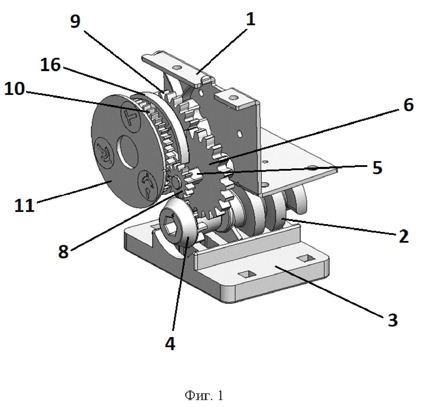
Description
Полезная модель относится к области электротехники и может быть использована в выдвижных блоках низковольтного комплектного устройства (шкафа) для перемещения выдвижного блока в требуемые положения: "Выкачено", "Тест", "Вкачено".The utility model relates to the field of electrical engineering and can be used in withdrawable units of a low-voltage complete device (cabinet) to move the withdrawable unit to the required positions: "Disconnected", "Test", "Connected".
Известен приводной механизм выдвижного блока низковольтного комплектного устройства (RU145041U1), содержащий узел привода, состоящий из корпуса с размещенным внутри валом с червячным пазом, взаимодействующим с упором, и узел фиксации привода, взаимодействующий с валом, при этом на задней торцевой части вала привода выполнены пазы для блокирования вращения вала, узел фиксации привода содержит шток с выступами, кнопку снятия блокировки и возвратную пружину, причем шток установлен на корпусе привода с возможностью продольного перемещения, на одном конце штока закреплена кнопка снятия блокировки, выходящая за лицевую панель выдвижного блока, на другом выполнен первый выступ, взаимодействующий с соответствующим пазом на задней торцевой части вала привода, возвратная пружина закреплена на корпусе привода и воздействует на конец штока с первым выступом, и дополнительно в него (приводной механизм) введен узел блокировки автоматического выключателя, содержащий закрепленные на корпусе привода кронштейн и ограничитель, и расположенный между ними сектор, взаимодействующий с валом автоматического выключателя, при этом сектор установлен на кронштейне с возможностью вращения в вертикальной плоскости при включении и выключении автоматического выключателя и возможностью взаимодействия с вторым выступом штока, ограничитель и кронштейн имеют вырез для захода второго выступа штока в промежуточном положении выдвижного блока. На передней торцевой части вала привода, выходящей на лицевую панель выдвижного блока, может быть выполнен указатель положения выдвижного блока.A drive mechanism for a draw-out unit of a low-voltage complete device (RU145041U1) is known, containing a drive assembly consisting of a housing with a shaft placed inside with a worm groove interacting with a stop, and a drive fixation assembly interacting with the shaft, while grooves are made on the rear end of the drive shaft to block the rotation of the shaft, the drive fixing unit contains a rod with protrusions, a lock release button and a return spring, and the rod is mounted on the drive housing with the possibility of longitudinal movement, a lock release button is fixed at one end of the rod, extending beyond the front panel of the drawer, at the other it is made the first protrusion interacting with the corresponding groove on the rear end of the drive shaft, the return spring is fixed on the drive housing and acts on the end of the rod with the first protrusion, and in addition to it (the drive mechanism) a circuit breaker blocking assembly is introduced, containing a bracket and a limiter, and a sector located between them interacting with the circuit breaker shaft, while the sector is mounted on the bracket with the possibility of rotation in a vertical plane when the circuit breaker is turned on and off and the possibility of interacting with the second protrusion of the rod, the limiter and the bracket have a cutout for entering the second protrusion of the stem in the intermediate position of the withdrawable block. On the front end part of the drive shaft facing the front panel of the withdrawable unit, a position indicator of the withdrawable unit can be made.
Недостатком известного устройства является недостаточно четкая фиксация выдвижного блока в требуемом положении. При случайном повороте вала и при не отжатой кнопке блокировки может произойти деформация выступа штока, что впоследствии приведет к неработоспособности привода.The disadvantage of the known device is not clear fixation of the retractable unit in the desired position. If the shaft is accidentally rotated and the lock button is not released, deformation of the protrusion of the rod may occur, which will subsequently lead to the inoperability of the drive.
В качестве прототипа выбран приводной механизм выдвижного блока низковольтного комплектного устройства (RU160092U1), содержащий узел привода, состоящий из корпуса с размещенным внутри валом с червячным пазом, взаимодействующий с упором, узел фиксации, взаимодействующий с валом, узел блокировки, при этом на корпусе узла привода закреплен введенный кронштейн, выполненный Г-образной формы с продольным пазом для перемещения верх и вниз узла блокировки, на передней торцевой части вала узла привода выполнены глухие отверстия, узел фиксации, взаимодействующий с валом, установлен на передней стенке корпуса узла привода и содержит гильзу, внутри которой размещены пружина и сердечник, взаимодействующий с соответствующим глухим отверстием вала узла привода, а на задней стенке корпуса узла привода установлен введенный упор, взаимодействующий с выступом, выполненным на задней торцевой части вала, узел блокировки выполнен в виде согнутой П-образно пластины со стопорными элементами и лапками на концах, в отверстиях которых установлены направляющие с пружинами, а в ее верхней части в продольном отверстии закреплен рычаг с помощью крепежных элементов.As a prototype, the drive mechanism of the drawer of the low-voltage complete device (RU160092U1), containing the drive unit, consisting of a housing with a shaft placed inside with a worm groove, interacting with the stop, a fixation unit interacting with the shaft, a locking unit, is selected, while on the body of the drive unit the inserted bracket is fixed, made of L-shaped form with a longitudinal groove for moving the blocking unit up and down, blind holes are made on the front end part of the drive unit shaft, the fixation unit interacting with the shaft is installed on the front wall of the drive unit housing and contains a sleeve, inside which contains a spring and a core interacting with the corresponding blind hole of the drive unit shaft, and on the rear wall of the drive unit body there is an inserted stop interacting with a protrusion made on the rear end of the shaft, the blocking unit is made in the form of a U-shaped plate bent with locking elements and paws at the end x, in the holes of which guides with springs are installed, and in its upper part in the longitudinal hole a lever is fixed with the help of fasteners.
В выбранном прототипе частично устранены недостатки аналога (RU145041U1), но при этом конструкция-прототип характеризуется высокой технической сложностью ряда деталей (вал узла привода, узел фиксации) и малой ремонтопригодностью.In the selected prototype, the shortcomings of the analog (RU145041U1) are partially eliminated, but at the same time, the prototype design is characterized by high technical complexity of a number of parts (shaft of the drive unit, fixation unit) and low maintainability.
Задачей (технической проблемой) полезной модели являлось упрощение устройства за счёт применения максимального числа стандартизированных и унифицированных деталей с высокой ремонтопригодностью и заменяемостью.The task (technical problem) of the utility model was to simplify the device by using the maximum number of standardized and unified parts with high maintainability and replaceability.
Технический результат - повышение надёжности устройства.The technical result is an increase in the reliability of the device.
Указанная задача решается приводным механизмом выдвижного блока низковольтного шкафа, содержащим узел привода, состоящий из корпуса с размещенным внутри червячным валом, узел фиксации и узел блокировки, в котором, согласно предложению, узел блокировки вращения червячного вала в требуемых крайних точках выполнен в виде двухступенчатой зубчатой передачи, установленной на корпусе приводного механизма, при этом ведущая шестерня зубчатой передачи установлена на передней торцевой части червячного вала, а ведомое колесо второй ступени зубчатой передачи выполнено с ограничением угла поворота, узел фиксации содержит рычаг, установленный на штоке автоматического выключателя и связанный с защитной шторкой, закрывающей доступ к гнезду управления червячным валом и блокирующей поворот ведомого колеса второй ступени зубчатой передачи при включенном состоянии автоматического выключателя.This task is solved by the drive mechanism of the drawer of the low-voltage cabinet, containing the drive unit, consisting of a housing with a worm shaft placed inside, a fixation unit and a blocking unit, in which, according to the proposal, the unit for blocking the rotation of the worm shaft at the required extreme points is made in the form of a two-stage gear mounted on the housing of the drive mechanism, while the drive gear of the gear is mounted on the front end of the worm shaft, and the driven wheel of the second stage of the gear is made with a rotation angle limitation, the fixation unit contains a lever mounted on the rod of the circuit breaker and associated with a protective shutter, closing access to the worm shaft control socket and blocking the rotation of the driven wheel of the second gear stage when the circuit breaker is on.
Целесообразно на устройстве установить средство индикации положения выдвижного блока, выполненное, например, из ведущей шестерни, установленной на промежуточном валу двухступенчатой передачи узла блокировки и ведомого колеса, на котором закреплена пластина с графическим обозначением положений перемещения выдвижного блока.It is advisable to install on the device a means for indicating the position of the drawer, made, for example, from a drive gear mounted on the intermediate shaft of the two-stage transmission of the blocking unit and the driven wheel, on which a plate with a graphic designation of the movement positions of the drawer is fixed.
Полезная модель поясняется чертежами.The utility model is illustrated by drawings.
На фиг. 1 показан внешний вид приводного механизма выдвижного блока низковольтного шкафа с лицевой стороны.In FIG. 1 shows the external view of the low-voltage cabinet drawer drive mechanism from the front side.
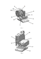
На фиг. 2 показан внешний вид приводного механизма выдвижного блока низковольтного шкафа с тыльной стороны без узла фиксации.In FIG. 2 shows the external view of the drive mechanism of the drawer of the low-voltage cabinet from the rear side without the fixation unit.
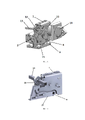
На фиг. 3 показан внешний вид приводного механизма выдвижного блока низковольтного шкафа с лицевой стороны с узлом фиксации.In FIG. 3 shows the external view of the drive mechanism of the drawer of the low-voltage cabinet from the front side with the locking unit.
На фиг. 4 показан узел фиксации.In FIG. 4 shows the fixation assembly.
На фиг. 5 показан сектор с пазами узла фиксации.In FIG. 5 shows the sector with the grooves of the fixation unit.
Приводной механизм выдвижного блока низковольтного шкафа крепится к основанию выдвижного блока и обеспечивает его продольное перемещение в требуемые положения. Приводной механизм состоит из корпуса 1, внутри которого в отверстиях боковых стенок зафиксирован червячный вал 2. Червячный вал взаимодействует с червячной рейкой 3, которая закреплена на стационарной части шкафа (не показан). На передней торцевой части червячного вала 2 закреплена ведущая шестерня 4 двухступенчатой зубчатой передачи с внутренним отверстием в виде шестигранника (гнездо управления червячным валом).The drive mechanism of the drawer of the low voltage cabinet is attached to the base of the drawer and ensures its longitudinal movement to the required positions. The drive mechanism consists of a
На промежуточном валу 5 установлены: ведомое колесо 6 первой ступени двухступенчатой передачи, ведущая шестерня 7 второй ступени, шестерня 8 средства индикации.On the
На ведомом валу двухступенчатой передачи установлены: ведомое колесо 9, ведомое колесо 10 средства индикации с платиной 11 с графическим обозначением положений перемещения выдвижного блока.On the driven shaft of the two-stage transmission, the following are installed: the driven
Поворот ведомого колеса 9 второй ступени ограничен углом 120 градусов, ограничителем может служить увеличенный зуб на колесе 9.The rotation of the driven
Узел фиксации обеспечивает блокирование включения автоматического выключателя в промежуточных положениях выдвижного блока и блокирование перемещения выдвижного блока при включенном автоматическом выключателе. Узел фиксации содержит следующие элементы, закрепленные на сборном корпусе 1:The locking unit ensures blocking of the switching on of the circuit breaker in the intermediate positions of the drawer and blocking of the movement of the drawer when the circuit breaker is on. The fixation unit contains the following elements fixed on the prefabricated body 1:
- рычаг 12, взаимодействующий со штоком 13 привода управления автоматическим выключателем с выносной рукояткой 14 и защитную шторку 15, связанную с рычагом 12;-
- диск 16 с пазами, жестко закрепленный на ведомом валу двухступенчатой зубчатой передачи. 2.3 узла 2 и синхронно вращающийся с ней.-
Устройство работает следующим образом.The device works as follows.
При включении автоматического выключателя посредством поворота штока 13 ручкой 14 на шторку 15 воздействует рычаг 12, и шторка 15 перекрывает доступ к гнезду управления червячным валом 2 (внутреннее шестигранное отверстие ведущей шестерни 4 двухступенчатой зубчатой передачи) и одновременно вступает в контакт с диском 16 в одном из трёх его возможных положений (фиг. 5).When the circuit breaker is turned on by turning the
При необходимости выдвижения блока (корпуса 1) автоматический выключатель отключается поворотом штока 13 ручкой 14. В гнездо управления червячным валом вставляется ключ (не показан), вращением которого обеспечивают вращение червячного вала 2 и соответственно перемещение выдвижного блока.If it is necessary to extend the block (case 1), the circuit breaker is turned off by turning the
Средство индикации положения выдвижного блока обеспечивает визуальный контроль положения выдвижного блока внутри шкафа (соответствующая пиктограмма на пластине 11).The means of indicating the position of the drawer provides visual control of the position of the drawer inside the cabinet (corresponding pictogram on plate 11).
Установка выдвижного блока по месту осуществляется вращением вала 2 в другую сторону при отключенном автоматическом выключателе.Installation of the withdrawable unit in place is carried out by rotating the
Опытные образцы предлагаемого устройства показали плавность и безотказность работы всех элементов, доступность и простоту обслуживания.Prototypes of the proposed device showed the smoothness and failure-free operation of all elements, accessibility and ease of maintenance.
Claims (2)
Publications (1)
| Publication Number | Publication Date |
|---|---|
| RU213235U1 true RU213235U1 (en) | 2022-08-30 |
Family
ID=
Citations (6)
| Publication number | Priority date | Publication date | Assignee | Title |
|---|---|---|---|---|
| RU2321122C1 (en) * | 2006-12-28 | 2008-03-27 | Закрытое акционерное общество "Прогресс, зао" | Low-voltage switchgear and control gear |
| DE102007024977A1 (en) * | 2007-05-25 | 2008-11-27 | Siemens Ag | Front module, gear tray with such a front module and control cabinet with a variety of such equipment carrier |
| EP2151029B1 (en) * | 2007-05-25 | 2013-10-02 | Siemens Aktiengesellschaft | Locking device, front assembly, device carrier and control cabinet |
| RU145041U1 (en) * | 2014-05-13 | 2014-09-10 | Закрытое акционерное общество "НПО "Каскад" | DRIVING MECHANISM OF THE LOW-VOLTAGE COMPLETE DEVICE EXTRACTION BLOCK |
| RU160092U1 (en) * | 2015-04-13 | 2016-03-10 | Закрытое акционерное общество "ВОЛМАГ" | DRIVING MECHANISM OF THE LOW-VOLTAGE COMPLETE DEVICE EXTRACTION BLOCK |
| RU193987U1 (en) * | 2019-05-13 | 2019-11-22 | Дмитрий Валерьевич Хачатуров | Switchgear compartment of an electrical device |
Patent Citations (6)
| Publication number | Priority date | Publication date | Assignee | Title |
|---|---|---|---|---|
| RU2321122C1 (en) * | 2006-12-28 | 2008-03-27 | Закрытое акционерное общество "Прогресс, зао" | Low-voltage switchgear and control gear |
| DE102007024977A1 (en) * | 2007-05-25 | 2008-11-27 | Siemens Ag | Front module, gear tray with such a front module and control cabinet with a variety of such equipment carrier |
| EP2151029B1 (en) * | 2007-05-25 | 2013-10-02 | Siemens Aktiengesellschaft | Locking device, front assembly, device carrier and control cabinet |
| RU145041U1 (en) * | 2014-05-13 | 2014-09-10 | Закрытое акционерное общество "НПО "Каскад" | DRIVING MECHANISM OF THE LOW-VOLTAGE COMPLETE DEVICE EXTRACTION BLOCK |
| RU160092U1 (en) * | 2015-04-13 | 2016-03-10 | Закрытое акционерное общество "ВОЛМАГ" | DRIVING MECHANISM OF THE LOW-VOLTAGE COMPLETE DEVICE EXTRACTION BLOCK |
| RU193987U1 (en) * | 2019-05-13 | 2019-11-22 | Дмитрий Валерьевич Хачатуров | Switchgear compartment of an electrical device |
Similar Documents
| Publication | Publication Date | Title |
|---|---|---|
| US4628636A (en) | Garage door operator mechanism | |
| CN103184820B (en) | Rotary pawl latch | |
| EP3561975B1 (en) | Base module for withdrawable switch | |
| US5808532A (en) | Motorized module for field assembly to circuit breakers | |
| EP2149948A2 (en) | Draw-out mechanism for molded case circuit breakers | |
| RU213235U1 (en) | Low voltage cabinet drawer drive mechanism | |
| US20230019861A1 (en) | Electric operating device for circuit breaker | |
| CN112700994A (en) | Five-prevention mechanical interlocking structure of upper isolating switch cabinet | |
| US20080151475A1 (en) | Locking Device and Withdrawable Rack Provided with Said Locking Device | |
| CN108963848B (en) | Motor-driven drive for push-pull operation in medium-voltage switchgear cabinets | |
| UA76018C2 (en) | Movable unit of a switch with additional disconnecting contacts for switchgear | |
| WO2015193128A1 (en) | Retraction mechanism | |
| EP3913648B1 (en) | Apparatus for operating electric switching device | |
| CN211628929U (en) | Five-prevention mechanical interlocking structure of upper isolating switch cabinet | |
| RU160092U1 (en) | DRIVING MECHANISM OF THE LOW-VOLTAGE COMPLETE DEVICE EXTRACTION BLOCK | |
| CN108631203B (en) | Draw-out type power distribution cabinet and auxiliary switch triggering mechanism on draw-out type power distribution cabinet | |
| EP3975355A1 (en) | Earthing switch interlock arrangement | |
| CN108551108B (en) | Draw-out type power distribution cabinet and three-position display assembly on same | |
| US3258552A (en) | Combined time-temperature switch device | |
| US3184565A (en) | Motor driven apparatus for the automatic closing of a switch | |
| CN220340353U (en) | Detection device for micro switch | |
| CN219779608U (en) | Isolation operating mechanism of inflatable cabinet | |
| CN220401256U (en) | Separation structure of pushing mechanism for draw-out type switch cabinet | |
| CN213816030U (en) | Operating device and circuit breaker | |
| CN115483068B (en) | Universal breaker safety door |