RU2130596C1 - Device for detection of change of pressure in pipe line - Google Patents
Device for detection of change of pressure in pipe line Download PDFInfo
- Publication number
- RU2130596C1 RU2130596C1 RU97101845/28A RU97101845A RU2130596C1 RU 2130596 C1 RU2130596 C1 RU 2130596C1 RU 97101845/28 A RU97101845/28 A RU 97101845/28A RU 97101845 A RU97101845 A RU 97101845A RU 2130596 C1 RU2130596 C1 RU 2130596C1
- Authority
- RU
- Russia
- Prior art keywords
- detector
- hole
- pressure
- shielded
- pipeline
- Prior art date
Links
Images

Abstract
Description
Предлагаемое изобретение относится к средствам измерительной техники и может быть использовано для мгновенного бесконтактного получения информации о несанкционированных изменениях давления в трубопроводе при транспортировке нефти, газа, а также в кабельных линиях дальней связи и на протяженных коммуникациях в таких отраслях промышленности, как химическая, атомная, металлургическая. The present invention relates to measuring equipment and can be used to instantly obtain contactless information on unauthorized changes in pressure in the pipeline during the transportation of oil, gas, as well as in cable lines for long-distance communications and long-distance communications in such industries as chemical, nuclear, metallurgical .
Предполагаемое изобретение основывается на использовании объективно существующих в природе активных (физических) свойств времени, а именно:
- способности мгновений передачи через изменение плотности времени информации от происходящего энтропийного необратимого процесса к детектору, в качестве которого может быть использовано любое вещество или система, например, механическая крутильная система ("крутильные весы"), резистор в мостовой схеме Уитстона или контактная пара (спай разных металлов) [1];
- свойства времени поглощаться (экранироваться) или отражаться веществами по законам геометрической оптики [2].The alleged invention is based on the use of objectively existing in nature active (physical) properties of time, namely:
- the ability of moments of transmission through a change in the density of time of information from an ongoing entropy irreversible process to a detector, which can be used as any substance or system, for example, a mechanical torsion system ("torsion balance"), a resistor in a Wheatstone bridge circuit or a contact pair (junction various metals) [1];
- the properties of time are absorbed (screened) or reflected by substances according to the laws of geometric optics [2].
Существование указанных физических свойств времени как не рассматриваемого современной физикой вида взаимодействия было экспериментально подтверждено в лабораторных условиях и натуральными измерениями [3 - 7]. The existence of the indicated physical properties of time as a form of interaction not considered by modern physics was experimentally confirmed in laboratory conditions and by natural measurements [3 - 7].
Для обнаружения изменения давления газов или жидкостей в трубопроводе, а также для измерения давления в практике используются всевозможные манометрические устройства, основанные на различных принципах. In order to detect changes in the pressure of gases or liquids in the pipeline, as well as to measure pressure in practice, various gauge devices based on various principles are used.
Известны радиоактивные манометрические устройства, в которых интенсивность ионизирующего излучения, проходящего через исследуемую среду, является функцией свойств среды (плотности состава и т.д.). В таких устройствах предполагается использование источника и приемника ионизирующего излучения (α-, β-, γ- излучение, нейтронное и рентгеновское излучения) [8]. Принцип измерения давления в указанных устройствах не связан с силовым воздействием среды на чувствительный элемент, что является достоинством приборов. Величина тока, измеренного с помощью высокочувствительного усилителя, пропорциональна плотности или абсолютному давлению газа. Однако радиоактивные манометрические устройства имеют ряд недостатков, к числу которых следует отнести невозможность оперативного обнаружения изменения давления на участках трубопровода, удаленных от места расположения детектора, а также невозможность применения радиоактивного манометрического устройства на реальных действующих трубопроводах, транспортирующих жидкие или газообразные продукты, имеющие обычно переменные значения таких параметров, как температура, химический состав, содержание механических примесей, влажность. Кроме того, к недостаткам радиоактивных манометрических устройств следует отнести сложность выполнения измерений, которая обусловлена необходимостью применения оператором радиоактивных изотопов, а также ограниченный диапазон измерений. Radioactive manometric devices are known in which the intensity of ionizing radiation passing through the medium under study is a function of the properties of the medium (composition density, etc.). In such devices, the use of a source and a receiver of ionizing radiation (α-, β-, γ-radiation, neutron and x-ray radiation) is assumed [8]. The principle of measuring pressure in these devices is not related to the forceful effect of the medium on the sensitive element, which is the advantage of the devices. The current measured with a highly sensitive amplifier is proportional to the density or absolute pressure of the gas. However, radioactive manometric devices have several disadvantages, including the impossibility of promptly detecting pressure changes in sections of the pipeline remote from the detector location, as well as the impossibility of using a radioactive gauge device in real existing pipelines transporting liquid or gaseous products, which usually have variable values such parameters as temperature, chemical composition, content of solids, humidity. In addition, the disadvantages of radioactive manometric devices include the difficulty of measuring, which is due to the need for the operator to use radioactive isotopes, as well as a limited measurement range.
Известны также следующие виды манометров: жидкостные (U-образные, колокольные, компрессионные), грузопоршневые, деформационные (мембранные, сильфонные, тубчатопружинные), электрические (емкостные, пьезоэлектрические, сопротивления), термокондуктометрические (терморезистивные, термоэлектрические), а также комбинированные. Манометры устанавливаются, как правило, вблизи точек отбора давления в местах, удобных для обслуживания [9]. У этих манометрических устройств отсутствует часть недостатков, присущих радиоактивным манометрическим устройствам, однако общими недостатками, характеризующими указанные виды манометрических устройств, являются:
- локальность измерений;
- необходимость контакта чувствительного элемента с измеряемой средой, которая может оказывать агрессивное тепловое, вибрационное и т.п. воздействие на чувствительный элемент;
- малый диапазон измерений;
- низкая чувствительность.The following types of pressure gauges are also known: liquid (U-shaped, bell, compression), deadweight, deformation (diaphragm, bellows, tubular spring), electric (capacitive, piezoelectric, resistance), thermoconductometric (thermoresistive, thermoelectric), as well as combined. Manometers are installed, as a rule, near pressure sampling points in places convenient for maintenance [9]. These gauge devices lack some of the disadvantages inherent in radioactive gauge devices, however, the common disadvantages characterizing these types of gauge devices are:
- locality of measurements;
- the need for contact of the sensitive element with the measured medium, which may have an aggressive thermal, vibration, etc. exposure to the sensing element;
- small measuring range;
- low sensitivity.
Все это приводит к ограниченности эксплуатационных возможностей. All this leads to limited operational capabilities.
Известен датчик давления [10], который содержит цилиндрический элемент, выполненный в виде упругой трубки с комбинированным отверстием. На цилиндрический элемент намотано световолокно, включенное в интерферометр, а полость трубки сообщена с источником измеряемого давления. Датчик предназначен для измерения флуктуаций давления газа или жидкости в системах с большим диапазоном изменения давления, однако обладает общим с описанными выше датчиками недостатком - локальностью измерения. A known pressure sensor [10], which contains a cylindrical element made in the form of an elastic tube with a combined hole. A fiber included in the interferometer is wound on the cylindrical element, and the tube cavity is in communication with the source of the measured pressure. The sensor is designed to measure fluctuations in gas or liquid pressure in systems with a wide range of pressure changes, however, it has a drawback common to the sensors described above - the measurement locality.
Наибольшее распространение в области контроля изменения давления при транспортировке нефти, газа получили деформационные, в частности пружинные манометры, которые монтируются на конце линии отбора давления. Схема такого устройства для обнаружения изменения давления II, наиболее близкого к предлагаемому, содержит трубопровод, в который в точке отбора вварен штуцер. Штуцер через запорный вентиль соединен с отборной трубкой, на конце которой установлен трехходовой кран, соединенный с измерительным прибором - манометром. The most widespread in the field of monitoring pressure changes during the transportation of oil and gas are deformation, in particular spring gauges, which are mounted at the end of the pressure line. The circuit of such a device for detecting a change in pressure II, which is closest to the proposed one, contains a pipeline into which a fitting is welded at the sampling point. The fitting is connected through a shut-off valve to a selected tube, at the end of which a three-way valve is installed, connected to a measuring device - a manometer.
Недостатком известного устройства является необходимость контакта чувствительного элемента (пружины Бурдона) с измеряемой средой, оказывающей на него неблагоприятное воздействие. Кроме того, в таком устройстве имеет место инерционность в фиксировании изменения давления, возрастающая с увеличением расстояния от места изменения давления до места расположения манометра. A disadvantage of the known device is the need for contact of the sensing element (Bourdon spring) with the measured medium, which has an adverse effect on it. In addition, in such a device there is an inertia in recording pressure changes, increasing with increasing distance from the place of pressure change to the location of the pressure gauge.
Предлагаемым изобретением решается задача быстрого обнаружения информации о событии, связанном с изменением давления в трубопроводе и произошедшем в отдалении от места расположения детектора при одновременном повышении эксплуатационных возможностей, надежности и чувствительности измерений. The present invention solves the problem of quickly detecting information about an event associated with a change in pressure in the pipeline and occurred in a distance from the location of the detector while increasing operational capabilities, reliability and sensitivity of measurements.
Для достижения этого технического результата в устройстве для обнаружения изменений давления в трубопроводе, содержащем узел отбора, для подведения жидкости или газа к детектору состоящий из штуцера, сочлененного с внутренним пространством трубопровода, запорного органа, соединяющего штуцер с отборной трубкой, а также измерительный прибор, узел отбора расположен в начале или конце трубопровода. Свободный конец отборной трубки заглушен и окружен экраном, в котором имеется отверстие. Напротив того отверстия располагается отверстие экранированного блока, внутри которого под отверстием смонтирован детектор, соединенный с измерительным прибором, расположенным за пределами экранированного блока. Детектор может быть соединен с измерительным прибором через измерительную схему, элементы которой для защиты от влияния информации, не подлежащей контролю, экранированы от детектора и от окружающей среды. To achieve this technical result, in a device for detecting changes in pressure in a pipeline containing a sampling unit, for supplying liquid or gas to the detector, consisting of a fitting connected to the interior of the pipeline, a locking member connecting the fitting to the selected tube, and a measuring device, assembly The selection is located at the beginning or end of the pipeline. The free end of the selection tube is plugged and surrounded by a screen in which there is a hole. Opposite the hole is the hole of the shielded block, inside of which a detector is mounted under the hole, connected to a measuring device located outside the shielded block. The detector can be connected to the measuring device through a measuring circuit, the elements of which are shielded from the detector and from the environment to protect against the influence of information not subject to monitoring.
Для обеспечения стабильной работы детектора и связанной с ним измерительной схемы отверстие экранированного блока должно быть загерметизировано. To ensure stable operation of the detector and the associated measuring circuit, the opening of the shielded unit must be sealed.
Отличительными признаками предлагаемого изобретения от указанного выше известного устройства для обнаружения изменения давления, оснащенного пружинным манометром, является наличие заглушенного конца на отборной трубке. Благодаря этому исключается контакт между чувствительным элементом измерительного прибора и измеряемой средой в полости трубопровода и обеспечивается отбор, направление, подведение и мгновенная передача внутритрубной информации к детектору, соединенному с измерительным прибором. Расположение узла отбора в начале или конце трубопровода дает возможность обнаруживать изменение давления жидкости или газа на любом участке трубопровода на всем его протяжении. Установка экранов вокруг заглушенного конца отборной трубки и вокруг детекторного блока защищает заглушенный конец отборной трубки и детектор от помех, обусловленных воздействием посторонних необратимых энтропийных процессов, например тепловых, изменения концентрации пыли в атмосфере, влажности атмосферы, химических компонентов и т.п. Вместе с тем наличие окон в упомянутых экранах и их взаимное расположение обеспечивает беспрепятственное прохождение внутритрубной информации к детектору. В том случае, когда детектор соединен с измерительным прибором через измерительную схему, экранирование элементов схемы от детектора препятствует их взаимному обмену информацией. Герметизация экранированного блока с детектором обеспечивает стабильную работу детектора и измерительной схемы. Distinctive features of the present invention from the above known device for detecting pressure changes, equipped with a spring pressure gauge, is the presence of a muffled end on the selected tube. This eliminates contact between the sensing element of the measuring device and the medium being measured in the pipe cavity and provides selection, direction, summing and instantaneous transfer of in-tube information to the detector connected to the measuring device. The location of the sampling unit at the beginning or end of the pipeline makes it possible to detect changes in the pressure of the liquid or gas on any part of the pipeline along its entire length. Installing screens around the muffled end of the sampling tube and around the detector unit protects the muffled end of the sampling tube and the detector from interference caused by irreversible entropic processes, such as thermal processes, changes in atmospheric dust concentration, atmospheric humidity, chemical components, etc. At the same time, the presence of windows in the said screens and their mutual arrangement provides unhindered passage of in-tube information to the detector. In the case when the detector is connected to the measuring device through the measuring circuit, the screening of the circuit elements from the detector prevents their mutual exchange of information. Sealing the shielded unit with the detector ensures stable operation of the detector and the measuring circuit.
Сущность изобретения поясняется чертежами, на которых изображены:
на фиг. 1 - принципиальная схема устройства для обнаружения изменений давления в трубопроводе;
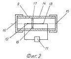
на фиг. 2 - пример выполнения экранированного детекторного блока в разрезе;
на фиг. 3 - конструкция экранированного детекторного блока, в котором детектор соединен с измерительным прибором через измерительную схему в разрезе.The invention is illustrated by drawings, which depict:
in FIG. 1 is a schematic diagram of a device for detecting changes in pressure in a pipeline;
in FIG. 2 shows an example of a sectional view of a shielded detector unit;
in FIG. 3 is a design of a shielded detector unit in which the detector is connected to the measuring device through a sectional measurement circuit.
Устройство для обнаружения изменений давления в трубопроводе (фиг. 1) содержит трубопровод 1, в котором в точке отбора смонтирован узел отбора, представляющий собой штуцер 2, вваренный в трубопровод 1, и запорный орган, например, вентиль 3, соединяющий штуцер 2 с отборной трубкой 4, один конец которой связан таким образом с внутренним пространством трубопровода 1, а другой конец отборной трубки 4 заглушен. Заглушенный конец отборной трубки 4 окружен экраном 5, выполненным, например, из листового алюминия толщиной 2 - 4 мм. В экране 5 имеется отверстие 6, предназначенное для прохождения внутритрубной информации к детектору 7, который смонтирован внутри экранированного блока 8 под отверстием 9, обеспечивающим вместе с отверстием 6 доступ информации к детектору 7. Отверстие 9 экранированного блока 8 загерметизировано с внутренней и внешней сторон, например, при помощи самоклеящейся полимерной пленки 10. Детектор 7 соединен с измерительным приором 11, расположенным за пределами экранированного блока 8. A device for detecting changes in pressure in the pipeline (Fig. 1) contains a pipeline 1, in which a sampling unit is mounted at the sampling point, which is a fitting 2 welded into the pipe 1, and a shut-off element, for example, a valve 3 connecting the fitting 2 to the selection tube 4, one end of which is thus connected with the interior of the pipe 1, and the other end of the selection tube 4 is plugged. The muffled end of the selection tube 4 is surrounded by a screen 5 made, for example, of sheet aluminum with a thickness of 2-4 mm. The screen 5 has a hole 6, intended for the passage of in-tube information to the detector 7, which is mounted inside the shielded
Весьма существенным для работы предлагаемого устройства для обнаружения изменений давления в трубопроводе является подбор материала отборной трубки 4, что связано с выявленной и экспериментально подтвержденной возможностью экранирования информации вследствие того, что плотность времени, переносящая информацию, ослабляется при взаимодействии с веществом [1], [3]. Например, стальной лист толщиной более 6 мм полностью экранирует информацию от энтропийного процесса, а кирпич полностью экранирует информацию при его толщине, равной 2 - 3 см. Руководствуясь указанным свойством плотности времени, на газопроводе с давлением газа до 75 кгс/см2 может быть использована, например, тонкостенная трубка из красной меди диаметром 10 х 8 мм или, например, высоконапорная трубка из резино-тканевого материала, пропускающая через себя информацию из внутритрубного пространства.The selection of the material of the selected tube 4 is very essential for the operation of the proposed device for detecting changes in pressure in the pipeline, which is associated with the identified and experimentally confirmed possibility of screening information due to the fact that the time density transferring information is weakened when interacting with the substance [1], [3 ]. For example, a steel sheet with a thickness of more than 6 mm completely shields information from the entropy process, and a brick completely shields information with its thickness equal to 2 - 3 cm. Based on the indicated property of time density, a gas pipeline with a gas pressure of up to 75 kgf / cm 2 can be used for example, a thin-walled tube made of red copper with a diameter of 10 x 8 mm or, for example, a high-pressure tube made of rubber-fabric material, which passes information from inside the tube.
В качестве конкретного примера выполнения экранированного детекторного блока 8 можно привести конструкцию, представленную на фиг. 2, где в качестве детектора 7 использован один из спаев двух металлов: олова и меди в дифференциальной контактной паре. Электроконтактная пара состоит из двух встречных спаев 12, 13 "олово-медь", размещенных в экранирующей трубке 14 из алюминия или плотного картона, торцы которой закрыты колпачками 15, 16, изготовленными как и трубка 14 из алюминия или картона. Спаи 12, 13 отделены друг от друга экранирующей, например картонной, перегородкой 17 с отверстием 18, предназначенным для выравнивания температуры спаев 12 и 13. Напротив спая 12, выполняющего роль детектора 7 (фиг. 1), расположено отверстие 9 для прохождения информации. Под воздействием информации в спае 12 происходит изменение структуры его вещества, в цепи возникает электрический ток, который усиливается и регистрируется вторичным прибором 11, в качестве которого могут быть использованы, например, фотокомпенсационный микровольтмикроамперметр Ф116/1 или зеркальный гальванометр типа М17/2. As a specific example of the shielded
Конкретным примером выполнения экранированного детекторного блока 8, соединенного с измерительным прибором 11 через измерительную схему, представляющую собой, например, измерительный мост Уитстона, является конструкция, изображенная на фиг. 3. Детектор 7 являющийся одним из резисторов моста Уитстона, а также остальные резисторы моста 19, 20, 21, образующие измерительную схему, и соединяющие их провода 22 размещены внутри цилиндрического экрана, образованного тремя вставленными друг в друга алюминиевыми трубками 23, 24, 25, между которыми расположены изолирующие втулки 26, 27. Противоположные торцы цилиндрического экрана закрыты алюминиевыми колпачками 28, 29, плотно прилегающими к торцам алюминиевых трубок 23, 24, 25. В одном из колпачков 28 напротив детектора 7 выполнено отверстие 9 для прохождения внутритрубной информации к детектору 7, загерметизированное с внутренней и внешней стороны самоклеящейся пленкой 10. Все провода 22 измерительного моста Уитстона помещены в оплеточные алюминиевые экраны 30. На выходе из экранированного детекторного блока 8 провода 22 загерметизированы герметиком 31. Промежутки между проводами 22, имеющиеся вдоль всего детекторного блока, способствуют выравниванию температуры воздуха внутри замкнутого объема детекторного блока 8. К одной из диагоналей моста Уитстона подключен источник 32 постоянного тока, а к другой - измерительный прибор 11. A specific example of a shielded
Мостовая измерительная схема может быть собрана, например, из металлопленочных резисторов типа ОМЛТ-0,125 сопротивлением 5,6 килоом, питание схемы постоянным током напряжением 25-30 вольт может осуществляться, например, от источника постоянного тока типа Б5-29. The bridge measuring circuit can be assembled, for example, from metal-film resistors of the OMLT-0.125 type with a resistance of 5.6 kilo-ohms, the circuit can be powered with a direct current voltage of 25-30 volts, for example, from a DC source of type B5-29.
В качестве измерительного прибора 11 на выходе мостовой измерительной схемы может быть подключен, например, фотокомпенсационный усилитель микровольтмикроамперметр Ф-116/1. Может быть предусмотрен вывод информации на ЭВМ. As a measuring
Работа устройства для обнаружения изменений давления в трубопроводе происходит следующим образом. The device for detecting changes in pressure in the pipeline is as follows.
Перед началом работы окно 9 (фиг. 1) экранированного блока 8 с детектором 7 устанавливается напротив окна 6 экрана 5 на расстоянии, не превышающем 2 см. При дальнейшем удалении блока 8 с детектором 7 от окна 6 экрана 5 происходит резкое падение амплитуды сигнала детектора, которая обратно пропорциональна расстоянию до места расположения источника информации [2], [3]. Затем открывается вентиль 3, соединяя внутреннее пространство трубки 4 с полостью трубопровода 1. При изменении давления в трубопроводе 1, например, по причине резкого изменения отбора продукта потребителем, вследствие утечки через трещины, при порыве трубопровода и т.п. информация об этом событии мгновенном передается через изменение плотности времени по внутритрубному пространству трубопровода 1 сквозь пропускающие информацию стенки отборной трубки 4, окна 6 и 9 к детектору 7. Before starting work, window 9 (Fig. 1) of the shielded
В случае выполнения детектора 7 в виде электроконтактной дифференциальной пары (фиг. 2) информация вызывает изменение в структуре вещества спая 12, что фиксируется измерительным прибором 11. In the case of the execution of the detector 7 in the form of an electric contact differential pair (Fig. 2), the information causes a change in the structure of the substance of the
При соединении детектора 7 с измерительным прибором 11 через измерительную схему, представляющую собой мост Уитстона (фиг. 3) после установки детекторного блока 8 напротив окна 6 экрана 5 необходимо произвести юстировку нуля мостовой измерительной схемы как до, так и после подачи электропитания от источника постоянного тока 32. Затем открывается вентиль 3, внутренние пространства трубопровода 1 и отборной трубки 4 соединяются, а изменения давления в трубопроводе 1 мгновенно через изменение плотности времени вызывает изменение сопротивления резистора-детектора 7, и электрический сигнал с выхода измерительной схемы усиливается и фиксируется измерительным прибором 11. When connecting the detector 7 to the measuring
Таким образом, предлагаемое устройство для обнаружения изменений давления в трубопроводе работает в режиме пассивного бесконтактного наблюдения за процессом в трубопроводе и не требует каких-либо специальных энергетических затрат, специальных монтажных работ и сооружения проводной или радиосвязи. Не требуется также и применение дорогостоящих материалов. Измерительная схема устройства проста и дает возможность обработки сигналов детектора на электронно-вычислительной машине. Thus, the proposed device for detecting changes in pressure in the pipeline operates in a passive contactless monitoring of the process in the pipeline and does not require any special energy costs, special installation work and the construction of wired or radio communications. The use of expensive materials is also not required. The measuring circuit of the device is simple and makes it possible to process the detector signals on an electronic computer.
Макет предполагаемого устройства для обнаружения изменений давления в трубопроводе прошел испытания в производственных условиях на технологическом продуктопроводе широкой фракции летучих углеводородов (сжиженном газе) на трассе Южно-Балакский газоперерабатывающий завод - Тобольский нефтехимический комбинат [7] , а также на газопроводе К.Р.П.Московского управления эксплуатации газопроводов "Мострансгаз", о чем свидетельствует приведенный в Приложении "Акт испытаний". The prototype of the proposed device for detecting changes in pressure in the pipeline was tested under production conditions on the technological product pipeline of a wide fraction of volatile hydrocarbons (liquefied gas) on the route of the South Balak gas processing plant - Tobolsk Petrochemical Plant [7], as well as on the K.R.P. gas pipeline. Mostransgaz Moscow Office of Gas Pipeline Operation, as evidenced by the Test Report in Appendix.
Источники информации. Sources of information.
1. Козырев Н.А. Время, как физическое явление. В книге "Моделирование и прогнозирование в биоэкологии". Латвийский государственный университет им. П.Стучки. Рига, 1988, с. 59-72. 1. Kozyrev N.A. Time is a physical phenomenon. In the book "Modeling and Forecasting in Bioecology". Latvian State University P. Knocks. Riga, 1988, p. 59-72.
2. Козырев Н.А. Астрономическое доказательство реальности четырехмерной геометрии Минковского. Сборник "Появление космических факторов на Земле и звездах". Серия "Проблемы исследования Вселенной". Вып. 9. -М.-Л.: АН СССР 1980, с. 85-93. 2. Kozyrev N.A. Astronomical evidence of the reality of four-dimensional Minkowski geometry. Collection "The emergence of cosmic factors on Earth and stars." Series "Problems of the Universe exploration". Vol. 9.-M.-L .: AN USSR 1980, p. 85-93.
3. Козырев Н.А., Насонов В.В. Новый метод определения тригонометрических параллаксов на основе измерения разности между истинным и видимым положением звезды. Астрометрия и небесная механика. Серия "Проблемы исследования Вселенной". Вып. 7, -М.-Л.: АН СССР 1978, с. 168-179. 3. Kozyrev N.A., Nasonov V.V. A new method for determining trigonometric parallaxes based on measuring the difference between the true and visible position of the star. Astrometry and celestial mechanics. Series "Problems of the Universe exploration". Vol. 7, M.-L.: Academy of Sciences of the USSR 1978, p. 168-179.
4. Лаврентьев М.М. и др. О дистанционном воздействии звезд на резистор. Докл. АН СССР. 1990, т. 314, N 2, c. 352-355. 4. Lavrentiev M.M. and others. On the remote effects of stars on a resistor. Doc. USSR Academy of Sciences. 1990, t. 314, N 2, c. 352-355.
5. Лаврентьев М.М. и др. О регистрации истинного положения Солнца. Докл. АН СССР. 1990, т. 315, N 2, с. 368-370. 5. Lavrentiev M.M. and others. On the registration of the true position of the Sun. Doc. USSR Academy of Sciences. 1990, t. 315, N 2, p. 368-370.
6. Лаврентьев М.М. и др. О регистрации реакции вещества на внешний необратимый процесс. Докл АН СССР, 1991, т. 317, N 3, c. 635-639. 6. Lavrentiev M.M. and others. On the registration of the reaction of a substance to an external irreversible process. Dokl. AN SSSR, 1991, v. 317, No. 3, p. 635-639.
7. Забелин В.Е. Отчет по выполнению работ согласно "Договору по проведение измерений мгновенной передачи и фиксирования информации от процесса аварийного изменения давления в продуктопроводе широкой фракции летучих углеводородов. Санкт-Петербург, 1991 г. Договор на период сентябрь-декабрь 1991 г. между М.Г.П. "Агро-Тест", г. Санкт-Петербург, и Производственным объединением магистральных нефтепроводов в Западной и Северо-Западной Сибири, г. Тюмень. 7. Zabelin V.E. Report on the implementation of work under the "Agreement on the measurement of instantaneous transmission and recording information from the process of emergency pressure changes in the product pipeline of a wide fraction of volatile hydrocarbons. St. Petersburg, 1991. Agreement for the period September-December 1991 between MGP "Agro-Test", St. Petersburg, and the Production Association of oil trunk pipelines in Western and North-Western Siberia, Tyumen.
8. Электрические измерения электрических и неэлектрических величин. /Под редакцией Е.С.Полищука.-Киев: 1984, с. 302. 8. Electrical measurements of electrical and non-electrical quantities. / Edited by E.S. Polishchuk.-Kiev: 1984, p. 302.
9. Чистяков В.С. Краткий справочник по теплотехническим измерениям. -М.: Энергоатомиздат, 1990, с. 127, 140. 9. Chistyakov V.S. Quick reference to thermotechnical measurements. -M .: Energoatomizdat, 1990, p. 127, 140.
10. Авторское свидетельство СССР N 857766, кл. G 01 L 23/06, опубл. 1981 г. 10. Copyright certificate of the USSR N 857766, cl. G 01
11. Иванов Г.М. и др. Теплотехнические измерения и приборы. Учебник для теплоэнергетических специальностей вузов. -М. : 1984, с. 115. рис. 11-31 - прототип. 11. Ivanov G.M. et al. Thermotechnical measurements and devices. Textbook for thermal power specialties of universities. -M. : 1984, p. 115. Fig. 11-31 is a prototype.
Claims (3)
Priority Applications (1)
| Application Number | Priority Date | Filing Date | Title |
|---|---|---|---|
| RU97101845/28A RU2130596C1 (en) | 1997-02-04 | 1997-02-04 | Device for detection of change of pressure in pipe line |
Applications Claiming Priority (1)
| Application Number | Priority Date | Filing Date | Title |
|---|---|---|---|
| RU97101845/28A RU2130596C1 (en) | 1997-02-04 | 1997-02-04 | Device for detection of change of pressure in pipe line |
Publications (2)
| Publication Number | Publication Date |
|---|---|
| RU97101845A RU97101845A (en) | 1999-03-20 |
| RU2130596C1 true RU2130596C1 (en) | 1999-05-20 |
Family
ID=20189727
Family Applications (1)
| Application Number | Title | Priority Date | Filing Date |
|---|---|---|---|
| RU97101845/28A RU2130596C1 (en) | 1997-02-04 | 1997-02-04 | Device for detection of change of pressure in pipe line |
Country Status (1)
| Country | Link |
|---|---|
| RU (1) | RU2130596C1 (en) |
Cited By (2)
| Publication number | Priority date | Publication date | Assignee | Title |
|---|---|---|---|---|
| WO2003078953A1 (en) * | 2002-03-15 | 2003-09-25 | 'limited Liability Company Scientific-Research Institute Of Natural Gases And Gas Technologies-Vniigaz' | Protective device for measuring instruments |
| CN112748040A (en) * | 2020-12-24 | 2021-05-04 | 郑州工程技术学院 | Slurry pipeline conveying density change detection meter and detection method |
-
1997
- 1997-02-04 RU RU97101845/28A patent/RU2130596C1/en not_active IP Right Cessation
Non-Patent Citations (2)
| Title |
|---|
| Иванов Г.М. и др. Теплотехнические измерения и приборы. Учебник для теплоэнергетических специальностей вузов. - М.: Энергоатомиздат, 1984, с.115. * |
| Лаврентьев М.М. и др. О регистрации истинного положения Солнца. Докл. АН СССР. 1990, т.315, N 2, с.368 - 370. Лаврентьев М.М. и др. О регистрации реакции вещества на внешний необратимый процесс. Докл. АН СССР. 1991, т.317, N 3, с.635 - 639. * |
Cited By (3)
| Publication number | Priority date | Publication date | Assignee | Title |
|---|---|---|---|---|
| WO2003078953A1 (en) * | 2002-03-15 | 2003-09-25 | 'limited Liability Company Scientific-Research Institute Of Natural Gases And Gas Technologies-Vniigaz' | Protective device for measuring instruments |
| CN112748040A (en) * | 2020-12-24 | 2021-05-04 | 郑州工程技术学院 | Slurry pipeline conveying density change detection meter and detection method |
| CN112748040B (en) * | 2020-12-24 | 2023-11-10 | 郑州工程技术学院 | Slurry pipeline conveying density change detection meter and detection method |
Similar Documents
| Publication | Publication Date | Title |
|---|---|---|
| US6807324B2 (en) | Method and apparatus for calibrating a distributed temperature sensing system | |
| Jones | Instrument Technology: Measurement of pressure, level, flow and temperature | |
| US20100284000A1 (en) | Method and apparatus for distributed sensing utilizing optical scattering in optical waveguides | |
| Huang et al. | Multi-parameter dynamical measuring system using fibre Bragg grating sensors for industrial hydraulic piping | |
| CN102564334A (en) | Long period fiber grating strain gauge for micro strain detection of high-temperature pipes | |
| Smith | Basic process measurements | |
| US4749855A (en) | Method of detecting liquid leakage | |
| Hofmann et al. | Analysis of the acoustic response in water and sand of different fiber optic sensing cables | |
| Xu et al. | Surface crack detection in Prestressed concrete cylinder pipes using BOTDA strain sensors | |
| RU2130596C1 (en) | Device for detection of change of pressure in pipe line | |
| Worsley et al. | Fibre optic four mode leak detection for gas, liquids and multiphase products | |
| US3864960A (en) | Vacuum leak detector | |
| CN103376135A (en) | Non-contact optical fiber device and method for measuring flows | |
| GB2150300A (en) | A corrosion probe | |
| Winter et al. | Optical fiber transducer for monitoring single-phase and two-phase flows in pipes | |
| Berthold III | Overview of prototype fiber optic sensors for future application in nuclear environments | |
| Failleau et al. | Development of facilities and methods for the metrological characterization of distributed temperature sensing systems based on optical fibres | |
| CN106122775A (en) | Pipeline leakage checking system and method thereof | |
| Holler et al. | Water temperature measurements with a Rayleigh backscatter distributed sensor | |
| KR20190133518A (en) | Leak detecting apparatus | |
| CN114005558A (en) | FBG real-time leakage monitoring method and system for main steam pipeline of nuclear power station | |
| Sylvia et al. | Development of sodium leak detectors for PFBR | |
| US5783747A (en) | Fluid analyzing detector for detecting the presence of a particular analyte in a fluid medium | |
| Kadir | Pipeline fault & leakage diagnosis in smart oil and gas field using electrical capacitance tomography: A review | |
| Hashemian et al. | Assessment of fiber optic pressure sensors |
Legal Events
| Date | Code | Title | Description |
|---|---|---|---|
| PC4A | Invention patent assignment |
Effective date: 20060120 |
|
| MM4A | The patent is invalid due to non-payment of fees |
Effective date: 20100205 |