RU212777U1 - COMPENSATOR FLANGED - Google Patents
COMPENSATOR FLANGED Download PDFInfo
- Publication number
- RU212777U1 RU212777U1 RU2022118877U RU2022118877U RU212777U1 RU 212777 U1 RU212777 U1 RU 212777U1 RU 2022118877 U RU2022118877 U RU 2022118877U RU 2022118877 U RU2022118877 U RU 2022118877U RU 212777 U1 RU212777 U1 RU 212777U1
- Authority
- RU
- Russia
- Prior art keywords
- pipes
- flanges
- compensator
- pipeline
- polymer reinforced
- Prior art date
Links
- 229920000642 polymer Polymers 0.000 claims abstract description 13
- 229910000831 Steel Inorganic materials 0.000 claims description 10
- 239000010959 steel Substances 0.000 claims description 10
- 210000001503 Joints Anatomy 0.000 claims description 8
- 239000000956 alloy Substances 0.000 claims description 3
- 229910045601 alloy Inorganic materials 0.000 claims description 3
- REDXJYDRNCIFBQ-UHFFFAOYSA-N aluminium(3+) Chemical class [Al+3] REDXJYDRNCIFBQ-UHFFFAOYSA-N 0.000 claims description 3
- 229910000975 Carbon steel Inorganic materials 0.000 claims 1
- 230000000694 effects Effects 0.000 abstract description 4
- XLYOFNOQVPJJNP-UHFFFAOYSA-N water Substances O XLYOFNOQVPJJNP-UHFFFAOYSA-N 0.000 abstract description 3
- 231100000078 corrosive Toxicity 0.000 abstract description 2
- 231100001010 corrosive Toxicity 0.000 abstract description 2
- 238000011089 mechanical engineering Methods 0.000 abstract description 2
- 239000000463 material Substances 0.000 description 8
- 238000007789 sealing Methods 0.000 description 7
- 230000001808 coupling Effects 0.000 description 3
- 238000010168 coupling process Methods 0.000 description 3
- 238000005859 coupling reaction Methods 0.000 description 3
- 230000005489 elastic deformation Effects 0.000 description 3
- 239000002184 metal Substances 0.000 description 3
- 230000035882 stress Effects 0.000 description 3
- 239000012080 ambient air Substances 0.000 description 2
- OKTJSMMVPCPJKN-UHFFFAOYSA-N carbon Chemical compound [C] OKTJSMMVPCPJKN-UHFFFAOYSA-N 0.000 description 2
- 229910052799 carbon Inorganic materials 0.000 description 2
- 238000006073 displacement reaction Methods 0.000 description 2
- 239000000789 fastener Substances 0.000 description 2
- 230000002159 abnormal effect Effects 0.000 description 1
- 239000002131 composite material Substances 0.000 description 1
- 238000007906 compression Methods 0.000 description 1
- 230000001066 destructive Effects 0.000 description 1
- -1 for example Inorganic materials 0.000 description 1
- 239000011521 glass Substances 0.000 description 1
- 238000009434 installation Methods 0.000 description 1
- 239000007788 liquid Substances 0.000 description 1
- 230000003446 memory effect Effects 0.000 description 1
- 239000004033 plastic Substances 0.000 description 1
- 230000002028 premature Effects 0.000 description 1
- 230000000717 retained Effects 0.000 description 1
- 230000003068 static Effects 0.000 description 1
- 230000003245 working Effects 0.000 description 1
Images

Abstract
Заявляемая полезная модель относится к области машиностроения, а именно к компенсационным устройствам - компенсаторам, предназначенным для устранения негативного влияния линейных расширений, возникающих при перепадах рабочего давления и температуры в трубопроводах, выполненных из полимерных армированных труб (ПАТ), по которым осуществляется транспортировка рабочей среды, в частности нефтепродуктов, агрессивных сред, воды. Технический результат, на достижение которого направлена заявляемая полезная модель, заключается в повышении эффективности компенсации продольных изменений длины трубопровода, состоящего из полимерных армированных труб. Дополнительным результатом является повышение герметичности.The claimed utility model relates to the field of mechanical engineering, namely to compensating devices - compensators designed to eliminate the negative effect of linear expansions that occur when operating pressure and temperature drops in pipelines made of polymer reinforced pipes (PAT) through which the working medium is transported, in particular oil products, corrosive media, water. The technical result, which the claimed utility model is aimed at, is to increase the efficiency of compensating for longitudinal changes in the length of a pipeline consisting of polymer reinforced pipes. An additional result is an increase in tightness.
Указанный технический результат достигается тем, что компенсатор фланцевый включает внешний патрубок, охватывающий внутренний патрубок, а также фланцы, стягиваемые болтами, при этом внутри внешнего патрубка коаксиально ему и симметрично относительно поперечной оси расположены с зазором два внутренних патрубка, конусные отверстия которых направлены навстречу друг другу, при этом все патрубки выполнены из отрезков полимерных армированных труб и снабжены соединительными фланцами, причем на внутренних патрубках дополнительно смонтированы упорные фланцы, через пружинные шайбы скрепленные друг с другом стяжными болтами, а посредством шпилечных регулировочных и ограничительных шпилечных соединений связаны с соединительными фланцами. 5 з.п. ф-лы, 1 ил.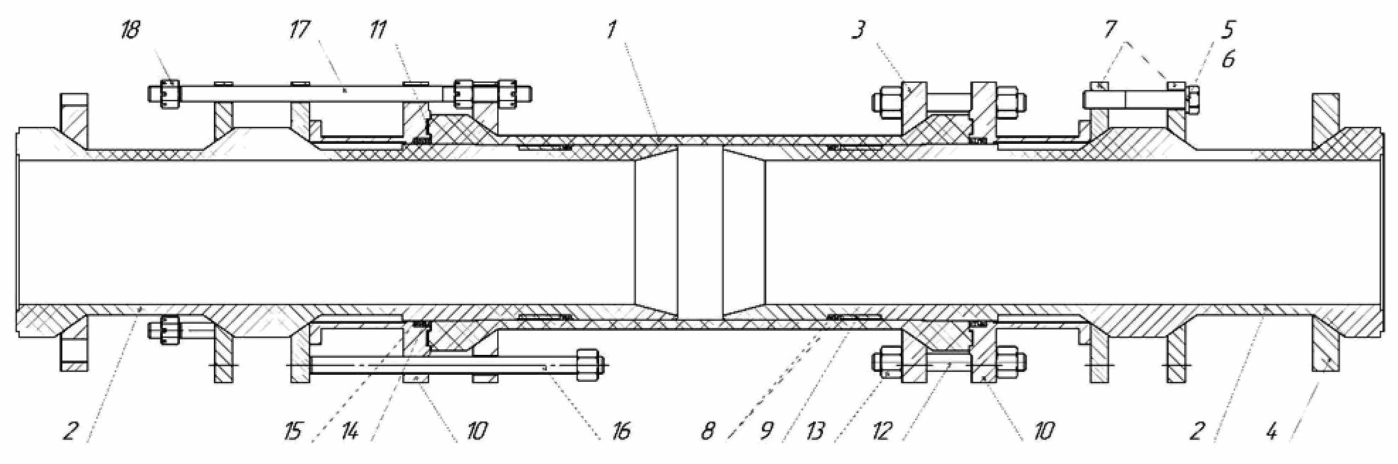
Description
Заявляемая полезная модель относится к области машиностроения, а именно к компенсационным устройствам - компенсаторам, предназначенным для устранения негативного влияния линейных расширений, возникающих при перепадах рабочего давления и температуры в трубопроводах, выполненных из полимерных армированных труб (ПАТ), по которым осуществляется транспортировка рабочей среды, в частности нефтепродуктов, агрессивных сред, воды. The claimed utility model relates to the field of mechanical engineering, namely to compensating devices - compensators designed to eliminate the negative effect of linear expansions that occur when operating pressure and temperature drops in pipelines made of polymer reinforced pipes (PAT) through which the working medium is transported, in particular oil products, corrosive media, water.
Известно, что применение компенсаторов в составе трубопроводов обусловлено необходимостью их защиты от негативных воздействий, вызываемых перепадами температур окружающего воздуха или транспортируемой среды, а также перепадами рабочего давления транспортируемой среды. К отрицательным факторам можно отнести и дополнительные напряжения, возникающие в стенках труб, превышение нагрузок, действующих на опоры трубопровода, нарушение герметичности фланцевых соединений и другие.It is known that the use of compensators as part of pipelines is due to the need to protect them from negative impacts caused by temperature changes in the ambient air or the transported medium, as well as changes in the working pressure of the transported medium. Negative factors include additional stresses arising in the walls of pipes, excess loads acting on pipeline supports, violation of the tightness of flange joints, and others.
Актуальной проблемой при эксплуатации магистральных трубопроводов, в том числе состоящих из ПАТ, является обеспечение возможности выдерживать высокие рабочие температуры и перепады рабочего давления в диапазоне от минимальных до максимальных значений, а также герметичность соединения. An urgent problem in the operation of main pipelines, including those consisting of PAT, is to ensure the ability to withstand high operating temperatures and operating pressure drops in the range from minimum to maximum values, as well as the tightness of the connection.
Известно, что трубопроводы коренным образом отличаются от любых обычных конструкций, подверженных вибрации, т.к. имеют специфический источник вибраций в виде пульсирующего рабочего потока газа или жидкости в трубах, что приводит к потере мощности из-за высоких мгновенных давлений и температур и оказывает разрушительное действие. Пульсация давления снижает пропускную способность трубопровода и, соответственно, уменьшает его производительность.It is known that pipelines are fundamentally different from any conventional structures subject to vibration, since. have a specific source of vibration in the form of a pulsating working flow of gas or liquid in pipes, which leads to a loss of power due to high instantaneous pressures and temperatures and has a destructive effect. Pressure pulsation reduces the throughput of the pipeline and, accordingly, reduces its performance.
Под воздействием вибраций трубопроводы подвергаются деформациям, возникающих в результате приложения нагрузки и приводящих к изменениям формы и размеров деталей. Такие изменения могут быть временными (упругие деформации, исчезающие после снятия нагрузки) или остаточными (пластические деформации, остающиеся после снятия нагрузки).Under the influence of vibrations, pipelines are subjected to deformations resulting from the application of a load and leading to changes in the shape and dimensions of parts. Such changes can be temporary (elastic deformations that disappear after the load is removed) or permanent (plastic deformations that remain after the load is removed).
Проблема обеспечения устойчивости трубопровода связана с компенсацией линейных расширений трубопроводов, снижающих напряженно-деформированное состояние до безопасного уровня. В свою очередь, перемещение трубы складывается из ее движения как целого и деформации ее осевой линии. Для того, чтобы существенно уменьшить этот вид деформации, в трубопроводах предусматривают специальные элементы, например компенсаторы, предназначенные для крепления элементов, присоединенных к трубопроводу, и восприятия тех или иных нагрузок.The problem of ensuring the stability of the pipeline is associated with the compensation of linear expansions of pipelines, which reduce the stress-strain state to a safe level. In turn, the movement of the pipe is made up of its movement as a whole and the deformation of its centerline. In order to significantly reduce this type of deformation, special elements are provided in the pipelines, for example, compensators designed to fasten the elements attached to the pipeline and absorb certain loads.
Пульсации давления рабочей среды в трубопроводе приводят и к преждевременному износу контрольно-измерительной аппаратуры и нарушению точности ее показаний, причем погрешность показаний может достигать значительных величин. Pulsations in the pressure of the working medium in the pipeline lead to premature wear of the control and measuring equipment and a violation of the accuracy of its readings, and the reading error can reach significant values.
Для снижения аэродинамического сопротивления, уменьшения влияния скоростного напора потока рабочей среды и исключения механических повреждений в конструкции компенсатора предусмотрены внутренние направляющие патрубки. Компенсаторы эффективны для обеспечения выравнивания температурного расширения и несоосности трубопроводов; предотвращения разрушения труб при деформации; присоединения напорных и всасывающих трубопроводов к агрегатам, таким как насосы, турбины, компрессоры, двигатели и т. д., а также снижения вибрационных нагрузок и герметизации трубопроводов. To reduce aerodynamic resistance, reduce the influence of the dynamic pressure of the working medium flow and exclude mechanical damage, internal guide pipes are provided in the design of the compensator. Expansion joints are effective for equalizing thermal expansion and misalignment of pipelines; preventing the destruction of pipes during deformation; connecting pressure and suction pipelines to units such as pumps, turbines, compressors, engines, etc., as well as reducing vibration loads and sealing pipelines.
Компенсатор выполняют с возможностью изменения его длины для того, чтобы компенсировать изменения длины трубопровода. Принцип работы компенсаторов прост. Так, например, при нагревании трубопровода и, соответственно, его удлинении компенсатор сжимается и таким образом компенсирует удлинение трубопровода. При охлаждении трубопровода, когда материал трубы сжимается, компенсатор, наоборот, деформируется путем удлинения.The compensator is made with the possibility of changing its length in order to compensate for changes in the length of the pipeline. The principle of operation of compensators is simple. So, for example, when the pipeline is heated and, accordingly, its elongation, the compensator is compressed and thus compensates for the elongation of the pipeline. When the pipeline is cooled, when the pipe material is compressed, the compensator, on the contrary, is deformed by elongation.
Преимущества фланцевых компенсаторов заключаются в их способности воспринимать и нивелировать изменения длины стыкуемых труб, при этом изменения длины зависят также от свойств системы и деформаций, проходящих по оси трубопровода, состоящего, как известно, из подвижных секций в виде стыкуемых труб, том числе, полимерных армированных труб (ПАТ). Помимо этого, компенсаторы такого типа способны поглощать возникающие изменения длины в пределах расчётной компенсирующей способности, и, тем самым, обеспечивают защиту трубопровода от разрушения. The advantages of flange compensators lie in their ability to perceive and level changes in the length of joined pipes, while changes in length also depend on the properties of the system and deformations passing along the axis of the pipeline, which, as is known, consists of movable sections in the form of joined pipes, including reinforced polymer pipes. pipes (PAT). In addition, expansion joints of this type are able to absorb the resulting changes in length within the calculated compensating capacity, and thus protect the pipeline from destruction.
Из предшествующего уровня техники известен компенсатор изменения длины магистрального трубопровода, включающий установленные с возможностью перемещения относительно друг друга внутренний и наружный стаканы с фланцами для присоединения к фланцам магистрального трубопровода, размещенное между ними уплотнительное средство, при этом дополнительно содержит равномерно расположенные вокруг стаканов направляющие элементы, каждый из которых проходит через сквозное отверстие во фланце одного из стаканов и один из концов которого закреплен на фланце другого стакана, а на свободном конце направляющего элемента установлен ограничитель перемещения фланца вдоль направляющего элемента, который выполнен в виде шпильки, один из концов которой закреплен на фланце стакана посредством стяжного соединения фланцев стакана и магистрального трубопровода, а ограничитель перемещения фланца выполнен в виде не менее двух последовательно установленных на шпильке гаек, а уплотнительное средство выполнено в виде уплотнительных колец, размещенных в кольцевых пазах наружного стакана (патент № 55922 на полезную модель «Компенсатор изменения длины магистрального трубопровода», дата подачи 16.03.2006 г., опубликовано 27.08.2006 г.).From the prior art, a compensator for changing the length of the main pipeline is known, including inner and outer sleeves installed with the possibility of movement relative to each other with flanges for attaching to the flanges of the main pipeline, a sealing means placed between them, while additionally containing guide elements evenly spaced around the sleeves, each of which passes through a through hole in the flange of one of the sleeves and one of the ends of which is fixed on the flange of the other sleeve, and at the free end of the guide element there is a limiter for the movement of the flange along the guide element, which is made in the form of a pin, one of the ends of which is fixed on the flange of the glass by means of a clamping connection of the flanges of the cup and the main pipeline, and the flange displacement limiter is made in the form of at least two nuts installed in series on the stud, and the sealing means is made in the form of a seal wear rings placed in the annular grooves of the outer sleeve (patent No. 55922 for utility model "Compensator for changing the length of the main pipeline", filed on 16.03.2006, published on 27.08.2006).
Известно сильфонное компенсирующее устройство, содержащее разгруженный компенсатор, состоящий из трех соосно расположенных сильфонов, фланцев и разгрузочных тяг, причем одинаковые крайние сильфоны меньшего диаметра жестко соединены двумя промежуточными фланцами со средним сильфоном большего диаметра и жестко связаны с концевыми фланцами, каждый концевой фланец соединен со вторым от него промежуточным фланцем посредством разгрузочных тяг, которые установлены вдоль оси разгруженного компенсатора с наружной стороны крайних сильфонов и внутри среднего сильфона, закреплены на соединенных фланцах, свободно пропущены через проходные отверстия промежуточных фланцев, расположенных между соединенными фланцами, и изолированы от рабочей среды внутри среднего сильфона гибкими элементами, а средний сильфон выполнен с эффективной площадью, которая рассчитана из условия равновесия распорных усилий в разгруженном компенсаторе и равна сумме эффективных площадей крайних сильфонов и эффективных площадей всех гибких элементов, при этом оно снабжено дополнительным разгруженным компенсатором, разгруженные компенсаторы установлены соосно и жестко соединены патрубком, крепления разгрузочных тяг с фланцами выполнены жесткими, а проходные отверстия промежуточных фланцев выполнены с возможностью обеспечения относительного перемещения разгрузочных тяг в этих отверстиях при максимальных угловых перемещениях разгруженных компенсаторов (патент № 2396480 на изобретение Сильфонное компенсирующее устройство», дата подачи 09.06.2009 г., опубликовано 10.08.2010 г.).A bellows compensating device is known, containing an unloaded compensator, consisting of three coaxially arranged bellows, flanges and unloading rods, and the same extreme bellows of a smaller diameter are rigidly connected by two intermediate flanges with an average bellows of a larger diameter and are rigidly connected to the end flanges, each end flange is connected to the second from it by an intermediate flange by means of unloading rods, which are installed along the axis of the unloaded compensator on the outside of the extreme bellows and inside the middle bellows, fixed on the connected flanges, freely passed through the through holes of the intermediate flanges located between the connected flanges, and isolated from the working medium inside the middle bellows flexible elements, and the middle bellows is made with an effective area, which is calculated from the condition of equilibrium of the spacer forces in the unloaded compensator and is equal to the sum of the effective areas of the outermost bellows and the effective areas in of all flexible elements, while it is equipped with an additional balanced compensator, the balanced compensators are installed coaxially and rigidly connected by a branch pipe, the fastening of the unloading rods with flanges is made rigid, and the through holes of the intermediate flanges are made with the possibility of ensuring relative movement of the unloading rods in these holes at maximum angular displacements of the unloaded compensators (patent No. 2396480 for the invention Bellows compensating device, filed on 06/09/2009, published on 08/10/2010).
Наиболее близким техническим решением к заявляемой полезной модели является термоуплотняемый компенсатор удлинений трубопровода с цилиндрическим корпусом, охватывающим гильзу, изготовленную из материала с коэффициентом удельного теплового расширения большим, чем у материала корпуса, и фланцами, стягиваемыми болтами, при этом концы гильзы имеют внешний диаметр меньший, чем внутренний диаметр корпуса для обеспечения герметизации корпуса при нагревании до рабочей температуры, причем гильза изготовлена из материала, обладающего эффектом памяти (патент № 176792 на полезную модель «Термоуплотняемый компенсатор», дата подачи 06.06.2017 г., опубликовано 29.01.2018 г.).The closest technical solution to the claimed utility model is a heat-sealed pipeline elongation compensator with a cylindrical body enclosing a sleeve made of a material with a coefficient of specific thermal expansion greater than that of the body material, and flanges tightened by bolts, while the ends of the sleeve have an outer diameter smaller, than the inner diameter of the body to ensure the sealing of the body when heated to the operating temperature, and the sleeve is made of a material with a memory effect (patent No. 176792 for a utility model "Heat-sealed compensator", filing date 06/06/2017, published 01/29/2018) .
Недостатки известных решений обусловлены низкой эффективностью компенсации продольных изменений из-за перекосов при перемещении или расстыковки трубопроводов в случае аномальных осевых отклонений, приводящих, в свою очередь, к потере герметичности.The disadvantages of the known solutions are due to the low efficiency of compensating for longitudinal changes due to distortions during movement or undocking of pipelines in the case of abnormal axial deviations, leading, in turn, to loss of tightness.
Кроме того, существуют трудности монтажа/демонтажа.In addition, there are difficulties in mounting/dismantling.
Технический результат, на достижение которого направлена заявляемая полезная модель, заключается в повышении эффективности компенсации продольных изменений длины трубопровода, состоящего из полимерных армированных труб.The technical result, which the claimed utility model is aimed at, is to increase the efficiency of compensating for longitudinal changes in the length of a pipeline consisting of polymer reinforced pipes.
Дополнительным результатом является повышение герметичности.An additional result is an increase in tightness.
Указанный технический результат достигается тем, что компенсатор фланцевый, включающий внешний патрубок, охватывающий внутренний патрубок, а также фланцы, стягиваемые болтами, согласно полезной модели внутри внешнего патрубка коаксиально ему и симметрично относительно поперечной оси расположены с зазором два внутренних патрубка с конусными отверстиями, направленными навстречу друг другу, при этом все патрубки выполнены из отрезков полимерных армированных труб и снабжены соединительными фланцами, причем на внутренних патрубках дополнительно смонтированы упорные фланцы, через пружинные шайбы скрепленные друг с другом стяжными болтами и посредством регулировочных и ограничительных шпилечных соединений связанные с соединительными фланцами.The specified technical result is achieved by the fact that the flanged compensator, including an external branch pipe, enclosing the inner branch pipe, as well as flanges tightened with bolts, according to the utility model, inside the outer branch pipe, coaxially to it and symmetrically with respect to the transverse axis, two internal branch pipes with conical holes directed towards to each other, while all the branch pipes are made of sections of polymer reinforced pipes and are equipped with connecting flanges, and on the inner pipes there are additionally mounted thrust flanges, through spring washers fastened to each other with tie bolts and connected to the connecting flanges by means of adjusting and restrictive pin connections.
Предлагаемая к защите полезная модель может быть использована, преимущественно в трубопроводах, образованных из полимерных армированных труб (ПАТ), через которые под давлением рабочей среды (Py) до 6 МПа и температуре - до +80°С транспортируются рабочие среды, в том числе агрессивные, и в случае изменения рабочей температуры и давления транспортируемой среды обеспечивается работоспособность трубопровода в пределах предусмотренных характеристик.The utility model proposed for defense can be used mainly in pipelines formed from reinforced polymer pipes (PAT), through which working media are transported under pressure of the working medium (P y ) up to 6 MPa and temperatures up to +80 ° C, including aggressive, and in the event of a change in the operating temperature and pressure of the transported medium, the operability of the pipeline is ensured within the specified characteristics.
Заявляемый фланцевый компенсатор содержит внешний направляющий патрубок 1 и два внутренних подвижных 2 патрубка, которые симметрично расположены относительно поперечной оси. Все патрубки представляют собой отрезки полимерной армированной трубы (ПАТ), преимущества которой обусловлены свойствами материала, обладающего стойкостью к агрессивным средам, транспортируемым по трубопроводу, и низким коэффициентом трения скольжения. Благодаря этому, срок службы компенсатора увеличивается, при этом срок службы полимерных армированных труб составляет не менее 25 лет.The inventive flange compensator contains an external guide pipe 1 and two internal
Помимо этого, в некоторых трубопроводах, выполненных из полимерных армированных труб, за счет упругой деформации материала возможны различные способы так называемой самокомпенсации температурного расширения. In addition, in some pipelines made of polymer reinforced pipes, due to the elastic deformation of the material, various methods of the so-called self-compensation of thermal expansion are possible.
Патрубки выполнены из той же трубы, что и трубопровод, благодаря чему достигается максимальная компенсация линейного расширения всей трубной системы. Помимо этого, такая конструкция позволяет справиться не только с подвижками труб и изменением их линейных размеров, но и с гидроударами, которые часто встречаются в трубопроводах.The branch pipes are made from the same pipe as the pipeline, due to which the maximum compensation for the linear expansion of the entire pipe system is achieved. In addition, this design allows you to cope not only with pipe movements and changes in their linear dimensions, but also with water hammer, which are often found in pipelines.
Патрубки 1, 2 снабжены металлическими соединительными фланцами 3, 4. На подвижных патрубках 2 через пружинные шайбы 5 с помощью стяжных болтов 6 смонтированы упорные фланцы 7, изготовленные из качественных конструкционных сталей, например, углеродистых или низколегированных.
Пружинные шайбы служат для предотвращения самоотвинчивания крепежных изделий при их упругой деформации под нагрузкой, что положительно влияет на сокращение линейных расширений. С учетом многократных температурных колебаний и особенно при больших перепадах температур применение пружинных фланцевых шайб служит своеобразным буфером, компенсирующим температурные линейные расширения. Spring washers serve to prevent self-unscrewing of fasteners during their elastic deformation under load, which has a positive effect on the reduction of linear expansions. Taking into account repeated temperature fluctuations and especially at large temperature differences, the use of spring flange washers serves as a kind of buffer that compensates for linear temperature expansions.
Пружинные шайбы обеспечивают сохранение первоначально приложенной нагрузки. Spring washers ensure that the initially applied load is retained.
Стяжные болты в виде удлиненных металлических стержней с нанесенной на них резьбой являются эффективным соединительным элементом, которые используют не только для создания надежной стяжки, но и для организации переноса динамической и статической нагрузок, благодаря чему исключается механическое деформирование и, соответственно, снижается линейное расширение, характерное при монтаже тяжелых, мощных конструкций, например, таких как протяженные магистральные трубопроводы.Coupling bolts in the form of elongated metal rods with threads applied to them are an effective connecting element that is used not only to create a reliable tie, but also to organize the transfer of dynamic and static loads, which eliminates mechanical deformation and, accordingly, reduces the linear expansion characteristic when installing heavy, powerful structures, for example, such as long main pipelines.
Стяжные болты легко демонтируются. Coupling bolts are easily dismantled.
За счет использования стяжных болтов и пружинных шайб увеличивается площадь контактного участка, что, в свою очередь, повышает герметичность соединения.Due to the use of tie bolts and spring washers, the area of the contact area increases, which, in turn, increases the tightness of the connection.
В зависимости от коэффициента температурного расширения болт увеличивается в длину. Так, например, при увеличении длины болта на 0,1-0,15 мм вполне достаточно для потери герметичности соединения. Поэтому использование стяжных болтов способствует увеличению герметичности соединения. Depending on the coefficient of thermal expansion, the bolt increases in length. So, for example, with an increase in the length of the bolt by 0.1-0.15 mm, it is quite enough to lose the tightness of the connection. Therefore, the use of tie bolts helps to increase the tightness of the connection.
На подвижном патрубке установлены грязесъемники 8, выполненные из упругого материала, например, резины, и металлическая ограничительная втулка 9, фиксирующая грязесъемники в рабочем положении. On the movable pipe installed
Упорные фланцы 10, размещенные на торцах направляющего патрубка, присоединены к нему через герметизирующие прокладки 11 с помощью крепежных соединений в виде шпилек 12 с гайками 13. Герметизирующие прокладки 11 изготовлены из композиционного уплотняющего прокладочного материала, например паронита. Упорные фланцы, шпильки и гайки выполнены из конструкционных углеродистых качественных или низколегированных сталей. В каждом упорном фланце 10 через стальное распорное кольцо 14 установлено по две резиновые манжеты 15.
Фланцы направляющего и подвижных патрубков связаны между собой с помощью шпилечных соединений, в которых используют регулировочную шпильку 16 и ограничительную шпильку 17 с гайками 18.The flanges of the guide and movable pipes are interconnected by means of stud joints, in which an adjusting
Использования регулируемых шпилек обеспечивает возможность устранения возникающих искажений.The use of adjustable studs makes it possible to eliminate the resulting distortion.
Ограничительные шпильки необходимы для недопущения запрещенных режимов работы гибких элементов, например, при одновременной работе компенсатора на растяжение и сдвиг или когда неподвижные опоры трубопроводов находятся достаточно далеко друг от друга.Limiting studs are necessary to prevent forbidden modes of operation of flexible elements, for example, when the expansion joint is operating in tension and shear at the same time, or when the fixed supports of pipelines are far enough from each other.
Подвижные патрубки размещены внутри направляющего патрубка коаксиально. При этом одним концом, выходящим за габариты направляющего патрубка, подвижные патрубки присоединяются к стыкуемой трубе магистрального трубопровода. Вторые концы подвижных патрубков заведены внутрь направляющего патрубка и установлены с зазором по отношению друг к другу для обеспечения компенсаций в случае изменения длины как трубопровода в целом, так и присоединяемой трубы в частности. Вторые концы подвижных патрубков выполнены с конусными отверстиями для обеспечения большей пропускной способности и малых скоростей выхода рабочей среды, что, в свою очередь, положительно влияет на снижение пульсаций давления и, соответственно, устраняет линейные изменения. Благодаря конусной форме достигается плотный контакт с поверхностью, что способствует увеличению герметичности соединения.Movable pipes are placed inside the guide pipe coaxially. In this case, with one end extending beyond the dimensions of the guide pipe, the movable pipes are connected to the joined pipe of the main pipeline. The second ends of the movable branch pipes are led into the guide branch pipe and installed with a gap in relation to each other to provide compensation in case of a change in the length of both the pipeline as a whole and the connected pipe in particular. The second ends of the movable nozzles are made with tapered holes to provide greater throughput and low speeds of the output of the working medium, which, in turn, has a positive effect on reducing pressure pulsations and, accordingly, eliminates linear changes. Due to the conical shape, tight contact with the surface is achieved, which helps to increase the tightness of the connection.
Полезная модель осуществляется следующим образом.The utility model is implemented as follows.
При сборке заявляемого компенсатора фланцевого на каждый подвижный патрубок последовательно устанавливают соединительные фланцы, грязесъемники и упорные фланцы, которые соединяют стяжными болтами, выполненными, например, из стали 35.When assembling the inventive flange compensator, connecting flanges, wipers and thrust flanges are sequentially installed on each movable branch pipe, which are connected by coupling bolts made, for example, of steel 35.
После этого монтируют резиновые манжеты и упорные фланцы, изготовленные, например, из стали 20.After that, rubber cuffs and thrust flanges are mounted, made, for example, from steel 20.
На полученную конструкцию надевают направляющий патрубок, при этом стыкуемые фланцы патрубков соединяют шпилечными соединениями, которые производят преимущественно из стали 35.A guide pipe is put on the resulting structure, while the abutting flanges of the pipes are connected with stud joints, which are made mainly from steel 35.
Перед установкой компенсатора в трубопровод из направляющего патрубка с помощью регулировочных шпилек выдвигают подвижные патрубки до заданного монтажного положения. В случае удлинения трубопровода из ПАТ, обусловленного увеличением давления или температурой транспортируемой среды и окружающего воздуха, в трубе возникают дополнительные напряжения, которые вызывают ее удлинение вдоль продольной оси и передаются на подвижные патрубки, прижимая их к направляющему патрубку. В результате длина компенсатора уменьшается, что обеспечивает защиту трубопровода от нарушения герметичности фланцевых соединений и потери продольной устойчивости. В случае снижения температуры стенок трубопровода из ПАТ и давления транспортируемой среды дополнительные напряжения в стенах трубопровода уменьшаются, что приводит к сжатию трубы вдоль продольной оси. Возникающее при этом усилие передается на подвижные патрубки, выдавливая их из направляющего патрубка. При этом длина компенсатора увеличивается, что также способствует защите трубопровода от нарушения герметичности фланцевых соединений и потери продольной устойчивости.Before installing the compensator in the pipeline, the movable pipes are pulled out of the guide pipe using the adjusting pins to a predetermined installation position. In the case of an extension of a PAT pipeline due to an increase in pressure or temperature of the transported medium and ambient air, additional stresses arise in the pipe, which cause it to elongate along the longitudinal axis and are transferred to the movable pipes, pressing them to the guide pipe. As a result, the length of the compensator is reduced, which ensures the protection of the pipeline from leakage of flanged joints and loss of longitudinal stability. In the case of a decrease in the temperature of the walls of the PAT pipeline and the pressure of the transported medium, additional stresses in the walls of the pipeline decrease, which leads to compression of the pipe along the longitudinal axis. The resulting force is transferred to the movable pipes, squeezing them out of the guide pipe. In this case, the length of the compensator increases, which also helps to protect the pipeline from leakage of flanged joints and loss of longitudinal stability.
Заявляемое устройство позволяет компенсировать изменение длины трубопровода, образованного из полимерных армированных труб (ПАТ), происходящее вследствие изменения температур транспортируемой среды и/или окружающей среды, а также из-за пульсаций давления и с учетом заданных рабочих свойств транспортируемой среды. Компенсатор имеет повышенные характеристики по герметичности, в том числе фланцевых соединений, благодаря чему увеличивается срок его эксплуатации. The claimed device makes it possible to compensate for the change in the length of a pipeline formed from polymer reinforced pipes (RRP), which occurs due to changes in the temperatures of the transported medium and / or the environment, as well as due to pressure pulsations and taking into account the specified working properties of the transported medium. The compensator has increased tightness characteristics, including flange connections, which increases its service life.
Claims (6)
Publications (1)
| Publication Number | Publication Date |
|---|---|
| RU212777U1 true RU212777U1 (en) | 2022-08-08 |
Family
ID=
Citations (5)
| Publication number | Priority date | Publication date | Assignee | Title |
|---|---|---|---|---|
| RU55922U1 (en) * | 2006-03-16 | 2006-08-27 | Общество с ограниченной ответственностью "Метрокампозит" | COMPENSATOR OF CHANGE OF LENGTH OF THE MAIN PIPELINE |
| FR2888913A1 (en) * | 2005-06-24 | 2007-01-26 | Eurl Gary Technologies Sarl | Rotular connection device for pipeline, has two lateral connection elements forming rotular assemblies with upstream and downstream parts, respectively, and adapter elements having central and two intermediary connection elements |
| RU2396480C1 (en) * | 2009-06-09 | 2010-08-10 | Владимир Ильич Кулухов | Bellows compensating facility |
| RU176792U1 (en) * | 2017-06-06 | 2018-01-29 | Федеральное государственное бюджетное образовательное учреждение высшего образования "Волгоградский государственный технический университет" (ВолгГТУ) | THERMAL SEALING COMPENSATOR |
| EP3618933A1 (en) * | 2017-05-02 | 2020-03-11 | Minimax GmbH & Co KG | Connection adapter for a container for a fire-extinguishing agent pertaining to a fire-extinguishing system |
Patent Citations (5)
| Publication number | Priority date | Publication date | Assignee | Title |
|---|---|---|---|---|
| FR2888913A1 (en) * | 2005-06-24 | 2007-01-26 | Eurl Gary Technologies Sarl | Rotular connection device for pipeline, has two lateral connection elements forming rotular assemblies with upstream and downstream parts, respectively, and adapter elements having central and two intermediary connection elements |
| RU55922U1 (en) * | 2006-03-16 | 2006-08-27 | Общество с ограниченной ответственностью "Метрокампозит" | COMPENSATOR OF CHANGE OF LENGTH OF THE MAIN PIPELINE |
| RU2396480C1 (en) * | 2009-06-09 | 2010-08-10 | Владимир Ильич Кулухов | Bellows compensating facility |
| EP3618933A1 (en) * | 2017-05-02 | 2020-03-11 | Minimax GmbH & Co KG | Connection adapter for a container for a fire-extinguishing agent pertaining to a fire-extinguishing system |
| RU176792U1 (en) * | 2017-06-06 | 2018-01-29 | Федеральное государственное бюджетное образовательное учреждение высшего образования "Волгоградский государственный технический университет" (ВолгГТУ) | THERMAL SEALING COMPENSATOR |
Similar Documents
| Publication | Publication Date | Title |
|---|---|---|
| RU212777U1 (en) | COMPENSATOR FLANGED | |
| CN211398967U (en) | Pipeline compensator with damping rings | |
| RU2122148C1 (en) | Bellows for compensation of deformation in pipe line | |
| CN104633363A (en) | Maintenance-free sleeve compensator | |
| CN208634626U (en) | A kind of sealing pipeline compensator | |
| CN209146584U (en) | Reinforcing formula non-metal expansion joint | |
| CN207178158U (en) | A kind of compressor with high pressure self-locking type flange | |
| RU104662U1 (en) | UNLOADED BELLOW COMPENSATOR | |
| CN206973111U (en) | A kind of high pressure self-locking type flange | |
| CN206973105U (en) | A kind of instrument with high pressure self-locking type flange | |
| RU8074U1 (en) | PIPELINE BELT COMPENSATOR | |
| RU226895U1 (en) | Bellows compensator | |
| CN108679340A (en) | A kind of steel made two-side casing expander | |
| CN219837719U (en) | Stainless steel expansion joint disassembly and assembly combined tool | |
| CN215807086U (en) | Metal compensator | |
| CN215981391U (en) | Flexible expansion joint for bent pipe | |
| CN219282724U (en) | High-pressure-bearing nonmetallic compensator | |
| CN220932376U (en) | Exhaust gas slip device and combustion chamber test system comprising same | |
| CN219655552U (en) | Material returning leg metal octagonal expansion joint | |
| RU1788381C (en) | Displacement damper for pipeline | |
| US11746940B2 (en) | Pipeline telescopic joint | |
| CN220061000U (en) | Pull rod compensator with elbow | |
| CN218031938U (en) | Steel lining tetrafluoro pipe | |
| RU24262U1 (en) | DEVICE FOR COMPENSATION OF GAS PIPE MOVEMENTS | |
| CN113738988B (en) | Detachable expansion joint |