RU2126104C1 - Converter - Google Patents
Converter Download PDFInfo
- Publication number
- RU2126104C1 RU2126104C1 RU96100549A RU96100549A RU2126104C1 RU 2126104 C1 RU2126104 C1 RU 2126104C1 RU 96100549 A RU96100549 A RU 96100549A RU 96100549 A RU96100549 A RU 96100549A RU 2126104 C1 RU2126104 C1 RU 2126104C1
- Authority
- RU
- Russia
- Prior art keywords
- nozzle
- trap
- gas
- regulator
- outlet
- Prior art date
Links
Images

Classifications
-
- B—PERFORMING OPERATIONS; TRANSPORTING
- B01—PHYSICAL OR CHEMICAL PROCESSES OR APPARATUS IN GENERAL
- B01D—SEPARATION
- B01D50/00—Combinations of methods or devices for separating particles from gases or vapours
- B01D50/20—Combinations of devices covered by groups B01D45/00 and B01D46/00
-
- B—PERFORMING OPERATIONS; TRANSPORTING
- B01—PHYSICAL OR CHEMICAL PROCESSES OR APPARATUS IN GENERAL
- B01D—SEPARATION
- B01D46/00—Filters or filtering processes specially modified for separating dispersed particles from gases or vapours
- B01D46/10—Particle separators, e.g. dust precipitators, using filter plates, sheets or pads having plane surfaces
-
- G—PHYSICS
- G05—CONTROLLING; REGULATING
- G05D—SYSTEMS FOR CONTROLLING OR REGULATING NON-ELECTRIC VARIABLES
- G05D16/00—Control of fluid pressure
- G05D16/20—Control of fluid pressure characterised by the use of electric means
- G05D16/2006—Control of fluid pressure characterised by the use of electric means with direct action of electric energy on controlling means
- G05D16/2013—Control of fluid pressure characterised by the use of electric means with direct action of electric energy on controlling means using throttling means as controlling means
-
- B—PERFORMING OPERATIONS; TRANSPORTING
- B01—PHYSICAL OR CHEMICAL PROCESSES OR APPARATUS IN GENERAL
- B01D—SEPARATION
- B01D2279/00—Filters adapted for separating dispersed particles from gases or vapours specially modified for specific uses
- B01D2279/35—Filters adapted for separating dispersed particles from gases or vapours specially modified for specific uses for venting arrangements
-
- Y—GENERAL TAGGING OF NEW TECHNOLOGICAL DEVELOPMENTS; GENERAL TAGGING OF CROSS-SECTIONAL TECHNOLOGIES SPANNING OVER SEVERAL SECTIONS OF THE IPC; TECHNICAL SUBJECTS COVERED BY FORMER USPC CROSS-REFERENCE ART COLLECTIONS [XRACs] AND DIGESTS
- Y10—TECHNICAL SUBJECTS COVERED BY FORMER USPC
- Y10T—TECHNICAL SUBJECTS COVERED BY FORMER US CLASSIFICATION
- Y10T137/00—Fluid handling
- Y10T137/2278—Pressure modulating relays or followers
- Y10T137/2322—Jet control type
-
- Y—GENERAL TAGGING OF NEW TECHNOLOGICAL DEVELOPMENTS; GENERAL TAGGING OF CROSS-SECTIONAL TECHNOLOGIES SPANNING OVER SEVERAL SECTIONS OF THE IPC; TECHNICAL SUBJECTS COVERED BY FORMER USPC CROSS-REFERENCE ART COLLECTIONS [XRACs] AND DIGESTS
- Y10—TECHNICAL SUBJECTS COVERED BY FORMER USPC
- Y10T—TECHNICAL SUBJECTS COVERED BY FORMER US CLASSIFICATION
- Y10T137/00—Fluid handling
- Y10T137/794—With means for separating solid material from the fluid
Landscapes
- Physics & Mathematics (AREA)
- Chemical & Material Sciences (AREA)
- Chemical Kinetics & Catalysis (AREA)
- Fluid Mechanics (AREA)
- General Physics & Mathematics (AREA)
- Engineering & Computer Science (AREA)
- Automation & Control Theory (AREA)
- Supply Devices, Intensifiers, Converters, And Telemotors (AREA)
- Nozzles (AREA)
- Jet Pumps And Other Pumps (AREA)
- Sampling And Sample Adjustment (AREA)
- Electrostatic Separation (AREA)
Abstract
Description
Изобретение относится к пневматическим инструментам, которые имеют вход подачи газа под давлением и электрический управляющий вход и обеспечивают формирование и выдачу регулируемого пневматического входа в функции электрического управляющего входного сигнала. The invention relates to pneumatic tools that have a gas inlet under pressure and an electric control input and provide the formation and output of an adjustable pneumatic input as an electric control input signal.
Такие инструменты определяют как преобразователи I/P, поскольку электрический управляющий входной сигнал обычно представлен электрическим током "I", а выход обычно представлен пневматическим давлением "P". В более узком смысле изобретение относится к устройствам улавливания частиц для преобразователей электрического тока в давление. Such instruments are defined as I / P converters, because the electrical control input signal is usually represented by an electric current "I", and the output is usually represented by pneumatic pressure "P". In a more narrow sense, the invention relates to particle capture devices for converting electric current to pressure.
Пользователь преобразователя электрического тока в давление обеспечивает подачу газа под давлением в устройство, причем подаваемый газ часто содержит вовлеченные в него частицы. Известные преобразователи электрического тока в давление (I/P-преобразователи) используют фильтры различных типов для удаления таких частиц из пневматической линии, прежде чем они смогут вызвать искажения выходного регулятора преобразователя или обусловить какие-либо иные нарушения его работы. The user of the electric current to pressure converter supplies gas under pressure to the device, and the gas supplied often contains particles involved. Known converters of electric current to pressure (I / P converters) use various types of filters to remove such particles from the pneumatic line before they can cause distortion of the output regulator of the converter or cause any other disturbances in its operation.
Частицы могут внести искажения в выходной результат преобразователя вследствие истирания прецизионных компонентов или блокировки малых отверстий I/P-преобразователя. Используемые для удаления таких частиц фильтры включают в себя экраны из проволочной сетки и комбинации фильтров с регуляторами, которые часто крепятся непосредственно к входному отверстию корпуса I/P-преобразователя. Такие фильтры эффективно удаляют большую часть вредных частиц и повышают тем самым надежность I/P-преобразователя. Particles can distort the output of the transducer due to abrasion of the precision components or blocking of the small holes of the I / P transducer. Filters used to remove such particles include wire mesh screens and filter combinations with controls that often attach directly to the inlet of the I / P converter housing. Such filters effectively remove most of the harmful particles and thereby increase the reliability of the I / P converter.
Однако в некоторых установках подавляемый воздух под давлением включает частицы, которые прилипают и накапливаются на чувствительных элементах I/P-преобразователя и которые невозможно эффективно отфильтровывать с помощью известных фильтров. В данном описании упомянутые частицы будут называться "липкими" частицами. Предполагается, что такие частицы содержат комбинацию капель масла, ржавчины и водяного пара. However, in some installations, suppressed air under pressure includes particles that adhere and accumulate on the sensitive elements of the I / P transducer and which cannot be effectively filtered using known filters. In this description, said particles will be called “sticky” particles. It is believed that such particles contain a combination of oil droplets, rust, and water vapor.
Согласно изобретению I/P-преобразователь содержит корпус, имеющий канал с впускным отверстием для приема по меньшей мере части подачи газа под давлением; регулятор газа, который включает в себя сопло регулятора, принимающее газ от выпускного отверстия канала; смещаемый дефлектор, реагирующий на электрический управляющий входной сигнал и взаимодействующий с соплом регулятора для регулирования пневматического выхода преобразователя, и уловитель частиц, расположенный в канале и включающий в себя пластину уловителя и сопло уловителя, причем сопло уловителя направляет газ на пластину уловителя. According to the invention, the I / P converter comprises a housing having a channel with an inlet for receiving at least a portion of the gas supply under pressure; a gas regulator, which includes a regulator nozzle receiving gas from a channel outlet; a movable deflector that responds to an electric control input signal and interacts with a regulator nozzle to regulate the pneumatic output of the converter, and a particle trap located in the channel and including a trap plate and a trap nozzle, the trap nozzle directing gas to the trap plate.
Сопло уловителя выполнено с возможностью выделения из газа нежелательных вовлеченных в него частиц посредством их осаждения на пластину уловителя так, чтобы уменьшенное количество таких частиц достигало регулятора газа. Согласно одному из аспектов изобретения сопло уловителя снабжено выпускным отверстием с площадью поперечного сечения, в 1-2 раза превышающей площадь поперечного сечения выпускного отверстия сопла регулятора. The trap nozzle is configured to separate unwanted particles from the gas by depositing them on the trap plate so that a reduced amount of such particles reaches the gas regulator. According to one aspect of the invention, the trap nozzle is provided with an outlet with a cross-sectional area 1-2 times greater than the cross-sectional area of the outlet of the regulator nozzle.
В предпочтительном варианте выполнения изобретения площадь выпускного отверстия сопла уловителя в 1,4-1,7 раза больше площади выпускного отверстия сопла регулятора для обеспечения поддержания относительно низкого падения давления у выпускного отверстия сопла уловителя при сохранении в значительной степени скоростей эжекции захваченных частиц в сопле регулятора. In a preferred embodiment of the invention, the area of the outlet of the trap nozzle is 1.4-1.7 times larger than the area of the outlet of the regulator nozzle to maintain a relatively low pressure drop at the outlet of the trap nozzle while maintaining substantially the ejection rates of the captured particles in the regulator nozzle.
Согласно другому аспекту изобретения, канал состоит из первого отверстия и второго отверстия, причем диаметр второго отверстия больше диаметра первого отверстия, а корпус снабжен буртиком, который располагается между первым и вторым отверстиями. В этом варианте выполнения настоящего изобретения сопло уловителя расположено, по меньшей мере частично, в первом отверстии, а пластина уловителя прижата к буртику. В другом варианте осуществления изобретения сопло уловителя заменено на матрицу сопел уловителя. According to another aspect of the invention, the channel consists of a first hole and a second hole, the diameter of the second hole being larger than the diameter of the first hole, and the housing is provided with a shoulder that is located between the first and second holes. In this embodiment of the present invention, the trap nozzle is located at least partially in the first hole, and the trap plate is pressed against the shoulder. In another embodiment, the trap nozzle is replaced with a trap nozzle array.
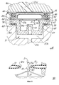
Фиг. 1 - вид в разрезе фрагмента IP-преобразователя, выполненного согласно настоящему изобретению; некоторые элементы показаны в форме блоков. FIG. 1 is a sectional view of a fragment of an IP converter made in accordance with the present invention; some elements are shown in block form.
Фиг. 1A и 1B - фрагменты фиг. 1, представленные в увеличенном масштабе. FIG. 1A and 1B are fragments of FIG. 1, shown on an enlarged scale.
Фиг. 2 - блок-схема, частично в разрезе, I/P-преобразователя, соответствующего изобретению. FIG. 2 is a block diagram, partially in section, of an I / P converter according to the invention.
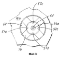
Фиг. 3 - вид по линии 3-3 на фиг. 1 в увеличенном масштабе. FIG. 3 is a view along line 3-3 of FIG. 1 on an enlarged scale.
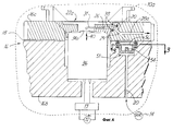
Фиг. 4 - вариант выполнения изобретения, сходный с показанным на фиг. 1, но с использованием пластины-заслонки. FIG. 4 is an embodiment of the invention similar to that shown in FIG. 1, but using a damper plate.
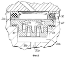
Фиг. 5 соответствует фиг. 1А, но иллюстрирует другой вариант выполнения изобретения. FIG. 5 corresponds to FIG. 1A, but illustrates another embodiment of the invention.
На всех чертежах компоненты, которые выполняют одни и те же или сходные функции, обозначены одинаковыми ссылочными позициями. In all the drawings, components that perform the same or similar functions are denoted by the same reference numerals.
Как показано на фиг. 1 и 2, I/P-преобразователь 10 принимает по меньшей мере часть подачи газа 14 под давлением и управляющий сигнал от источника электрического тока 12 и формирует пневматический выход в точке 46 с давлением, изменяющимся в функции управляющего сигнала. Подача газа под давлением 14 обычно включает воздух под давлением примерно на 20 фунтов на кв. дюйм (примерно 1,4•105 Н/м2) выше локального атмосферного давления; в данном случае пневматический выход в точке 46 может изменяться от примерно 3 фунтов на кв. дюйм (примерно 2,1•104 Н/м2) до примерно 15 фунтов на кв. дюйм (примерно 1,0•105 Н/м2) выше локального атмосферного давления.As shown in FIG. 1 and 2, the I /
Источник электрического тока 12 соединен со схемой 13 преобразователя 10 и может выдавать ток, изменяющийся от 4 до 20 миллиампер (мА) и по меньшей мере часть которого подается в преобразователь 10, причем величина тока обеспечивает управляющий сигнал для преобразователя 10. Как вариант, источник 12 может подавать в преобразователь 10 цифровой управляющий сигнал. The electric
Преобразователь 10 содержит корпус 16, который состоит из частей 16a, 16b, связанных одна с другой с помощью винтов (не показаны) и разделенных между собой прокладкой 18. В корпусе 16 выполнен канал 20, через который подается по меньшей мере часть газа, выдаваемого источником 14 газа под давлением. The
Модуль регулятора газа 22, который содержит головку 24 с сквозными отверстиями 26, 28, встречные сопла 30 и 32, смещаемый дефлектор 34 и исполнительный механизм 36, сопряжен с корпусом 16 и закреплен на нем винтами (не показаны). The
Уплотнительное кольцо 38 минимизирует утечки в месте соединения канала 20 и отверстия 26. Сопло 30 принимает газ из канала 20 через отверстие 26 и направляет его к противоположному соплу 32. Дефлектор 34, который расположен в непосредственной близости от выпускного отверстия 30a сопла 30 (см. фиг. 1В), перемещается параллельно двойной стрелке 40 для изменения объема потока газа, отводимого от сопла 32, благодаря чему и происходит регулирование пневматического давления в отверстии 28. O-
Как показано на фиг. 2, отверстие 28 в свою очередь сообщается с пневматическим усилителем 42, как и канал 44, передающий газ под давлением 14 непосредственно к усилителю 42. Как известно из уровня техники, давление воздуха в отверстии 28 регулирует объем подаваемого газа от источника газа 14, проходящего через усилитель 42, посредством чего осуществляется регулирование пневматического давления в выходном канале 46. As shown in FIG. 2, the
Конструкция и принцип работы механизма регулятора газа, включающего в себя перемещаемый дефлектор 34 и сопла 30, 32, детально описаны в патенте США N 4534376. В частности, дефлектор 34 предпочтительно имеет длину проволоки, которая удерживается перпендикулярно как к двойной стрелке 40, так и к оси сопла 30 посредством стойки 35. The design and operation of the gas regulator mechanism, including the
В патенте США N 4653523 описан вариант выполнения пневматического усилителя 42, который может быть использован в настоящем изобретении. US Pat. No. 4,653,523 describes an embodiment of a
Нежелательные частицы, захваченные потоком газа, могут нарушить нормальный режим работы преобразователя 10 в результате истирания прецизионных компонентов, например внутренних стенок сопла 30, передней и верхней поверхностей дефлектора 34 или передних частей сопла 32, и в результате засорения малых отверстий, например выпускного отверстия сопла 30a и впускного отверстия сопла 32a. Unwanted particles trapped in the gas stream can interfere with the normal operation of the
Известно использование комбинации фильтра-регулятора 48 у входного отверстия 50 датчика 10 для удаления по меньшей мере части таких нежелательных захваченных частиц из подаваемого газа 14 под давлением. Также известно использование сита или сетчатого фильтра 52 внутри канала 20 выше сопла 30 для дополнительного удаления частиц из газа, проходящего по каналу 20. It is known to use a combination of
Фильтр 52 может содержать блок двойного сита, причем одно сито имеет размер отверстий в 200 меш (стандартный размер отверстий сита по Тайлеру), а другое сито имеет размер или диаметр отверстий в 50 меш, при этом эти сита соединяются и удерживаются вместе с помощью зажимного кольца. Частицы, которые не были удалены с помощью фильтров 48 или 52, подают на дефлектор 34 или передние части сопла 32 и затем выносятся вместе с потоком газа. Однако было обнаружено, что фильтры, такие как фильтры 48 и 52, не обеспечивают эффективное удаление липких частиц. Такие липкие частицы могут содержать капли масла, остатки ржавчины или влаги либо комбинацию этих компонентов. Капли масла и остатки ржавчины могут переноситься от компрессоров, используемых для формирования источника газа 14 под давлением. The
Некоторые пользователи преднамеренно вводят капли масла при подаче газа 14, чтобы эти капли масла могли собираться на других конструктивных элементах, которые связаны с подачей газа 14, например клапанах, и смазывать их. Some users intentionally inject oil droplets when applying
Однако эти липкие частицы создают определенные проблемы в преобразователе 10, поскольку они не просто падают на дефлетор 14 и выносятся потоком, а прилипают и собираются на дефлекторе 34. However, these sticky particles create certain problems in the
Пневматическое давление на выходе в точке 46 очень чувствительно к положению дефлектора 34 относительно выпускного отверстия 30a сопла. Скапливание липких частиц на дефлекторе 34 фактически будет изменять форму и положение дефлектора 34, что в конечном итоге приводит к нежелательному сдвигу в пневматическом выходном давлении для конкретного прикладываемого на входе электрического управляющего сигнала. Кроме того, скапливание липких частиц на приемном сопле 32 может уменьшить размер впускного отверстия 32a сопла, что в конечном итоге может привести к еще большему смещению пневматического давления на выходе. The pneumatic outlet pressure at
Сужение выпускного отверстия 30a сопла обуславливает появление относительного ускорения потока газа в этой точке, так что сопло 30 эжектирует частицы, в том числе и липкие частицы, с относительно высокой скоростью по направлению к дефлектору 34 и соплу 32. The narrowing of the nozzle outlet 30a causes a relative acceleration of the gas flow at this point, so that the
Считается, что частицы, определяемые как "липкие", фактически характеризуются распределением адгезивных свойств, так что при конкретной скорости удара некоторые липкие частицы будут прилипать к мишени, тогда как другие частицы будут отскакивать подобно обычным "нелипким" частицам. Чем выше скорости, тем больший процент липких частиц будет прилипать к мишени. It is believed that particles defined as “sticky” are in fact characterized by a distribution of adhesive properties, so that at a specific impact speed, some sticky particles will adhere to the target, while other particles will bounce off like regular “non-sticky” particles. The higher the speed, the greater the percentage of sticky particles will stick to the target.
Чтобы уменьшить количество липких частиц, которые прилипают к и скапливаются на прецизионных компонентах, преобразователь 10 содержит уловитель частиц 51 специально для липких частиц. Уловитель частиц 51 содержит сопло 54 и пластину 56, расположенные в канале 20 выше сопла 30, при этом сопло 54 направляет поток газа на пластину 56. In order to reduce the amount of sticky particles that adhere to and accumulate on precision components, the
Сопло 54 снабжено выпускным отверстием 54a сопла (см. фиг. 1А), которое выполнено так, чтобы скорость захваченных частиц в выпускном отверстии 54a сопла была приблизительно равна скорости захваченных частиц в выпускном отверстии 30a сопла. Благодаря этому липкая частица, которая в силу своей скорости удара должна была бы прилипнуть к дефлектору 34, будет теперь прилипать к пластине 56. The
Поэтому пластина 56 действует как коллектор для таких частиц. С другой стороны, другая липкая частица, которая при ее скорости удара не будет прилипать к дефлектору 34, также не будет прилипать и к пластине 56, а будет вынесена потоком газа. В вариантах осуществления изобретения, в которых уловитель частиц 51 установлен в канале 20, как показано на фиг. 1 и 2, чтобы по существу весь газ, проходящий через сопло 54, также проходил через сопло 30, площадь выпускного отверстия 54a сопла (измеренная в плоскости, перпендикулярной оси сопла 54) по существу равна площади выпускного отверстия 30a сопла для достижения существенно одинаковых скоростей частиц. Therefore, the
За счет практически полного дублирования в сопле 54 условий потока газа через сопло 30 на пластине 56 будут собираться только те частицы, которые прилипли бы к дефлектору 34. Преимущество этого заключается в том, нарастание частиц на пластине 52 поддерживается на низком уровне и одновременно обеспечивается удаление наиболее "опасных" липких частиц из потока газа выше сопла 30. Due to the almost complete duplication in the
В вариантах осуществления изобретения, в которых уловитель частиц расположен в канале 44 между входным отверстием 50 и входом в канал 20, выпускное отверстие 54а сопла выполняется такого размера, чтобы скорость захваченных частиц в выпускном отверстии 54а сопла была приблизительно равна скорости движения захваченных частиц в выпускном отверстии 30a сопла. In embodiments where the particle trap is located in the
Однако предпочтительнее разместить уловитель частиц в канале 20, а не вверх по потоку в канале 44 в непосредственной близости от входного отверстия 50, чтобы гарантировать, что газ, который не проходит через сопло 30 или дефлектор 34, также не проходит через уловитель частиц. However, it is preferable to place the particle trap in the
Это поддерживает скапливание частиц на пластине 52 уловителя частиц на низком уровне. Не было обнаружено, что проходящие по каналу 44 непосредственно к пневматическому усилителю 42 липкие частицы могли заметно снизить эффективность преобразователя 10. This keeps the particle collection on the
Предпочтительнее, чтобы каждое из сопел 30, 54 имело радиальную симметрию относительно оси сопла. Для обеспечения широкого диапазона пневматического давления на выходе желательно поддерживать падение давления в канале 20 на низком уровне. Preferably, each of the
Для поддержания падения давления в выпускном отверстии 54a сопла на низком уровне относительно падения давления в выпускном отверстии 30a сопла при обеспечении примерно одинаковых скоростей частиц, о чем упоминали выше, необходимо, чтобы площадь выпускного отверстия 54a сопла превышала примерно в 1-2 раза площадь выпускного отверстия 30a сопла. In order to keep the pressure drop in the
В пределах этого диапазона более предпочтительным является более узкий диапазон от 1,4 до 1,7 раз. Вполне удовлетворительно работал образец, в котором выпускное отверстие 30a сопла имело диаметр в 0,016±0,01 дюйма (примерно 0,41±0,03 мм), а выпускное отверстие 54a сопла имело диаметр в 0,020±0,001 дюйма (примерно 0,51±0,03 мм). В этом случае отношение площадей было равно (0,020/0,016)2 или примерно 1,56.Within this range, a narrower range of 1.4 to 1.7 times is more preferred. The sample worked quite satisfactorily in which the nozzle outlet 30a had a diameter of 0.016 ± 0.01 inches (about 0.41 ± 0.03 mm) and the
На фиг. 1А показано, что канал 20 содержит расточные отверстия 20a, 20b, 20c, 20d в непосредственной близости от уловителя частиц 51. Согласно предпочтительному варианту каждое из отверстий 20a и 20d имеет диаметр приблизительно в 0,062 дюйма (примерно 1,6 мм), а каждое из отверстий 20b и 20c имеет диаметр приблизительно в 0,312 дюйма (примерно 7,92 мм) и приблизительно в 0,445 дюйма (примерно 11,3 мм) соответственно. In FIG. 1A, the
Часть 16b корпуса имеет буртик 58 между отверстиями 20b и 20c. Вкладыш 60 включает в себя фланец 62, втулку 64 и сопло 54. Часть 16a корпуса сопряжена с частью 16b корпуса. После разъединения частей корпуса 16a и 16b можно вынуть, прочистить или заменить прокладку 18, уплотнительное кольцо 66, проволочную сетку 52, пластинку 56, вкладыш 60 и прокладку 68. The housing portion 16b has a
При сборке часть 16а корпуса прижимается к фланцу 62 через прокладку 18, уплотнительное кольцо 66, проволочную сетку 52 и пластинку 56, прижимая фланец 62 к буртику 58. During assembly, the housing part 16a is pressed against the
Втулка 64 выступает вниз от фланца 62 до контактирования с основанием сопла 54, а сопло выступает в обратном направлении вверх к фланцу 62. Конец сопла 54, окружающий выпускное отверстие 54а сопла, заглублен от верхней части фланца 62 на расстояние "d". Если пластинка 56 выполнена плоской (как показано на чертежах), то расстояние "d" соответствует "зазору сопло/пластина" между выпускным отверстием 54а сопла и поверхностью столкновения пластины 56, на которой собираются липкие частицы. Для обеспечения накопления на этой поверхности только тех частиц, которые прилипали бы к дефлектору 34, необходимо, чтобы зазор сопло/пластина был идентичен "зазору сопло/дефлектор", который соответствует минимальному расстоянию "D" между дефлектором 34 и выпускным отверстием 30a сопла в диапазоне перемещений дефлектора 34. The
Зазор сопло/пластинка и зазор сопло/дефлектор лучше всего характеризовать не в абсолютных единицах измерения, например в миллиметрах, а в безразмерных кратных значениях диаметра (или эквивалентного поперечного размера в случае некруглого выпускного отверстия сопла) выпускного отверстия сопла, т. е. диаметра выпускного отверстия 54a сопла и диаметра выпускного отверстия 30a сопла соответственно. The nozzle / plate clearance and nozzle / deflector clearance are best characterized not in absolute units, for example in millimeters, but in dimensionless multiple values of the diameter (or equivalent transverse dimension in the case of a non-circular nozzle outlet) of the nozzle outlet, i.e., the diameter of the
В упомянутом выше образце, который работал вполне удовлетворительно, зазор сопло/пластина был равен примерно 2,5 (размер d приблизительно в 2,5 раза больше диаметра выпускного отверстия 54a сопла), тогда как зазор сопло/дефлектор был равен примерно 1 (размер D примерно равен диаметру выпускного отверстия 30a сопла). Предпочтительно зазор сопло/пластина имеет величину в пределах от ~1/5 до ~5 относительно зазора сопло/дефлектор. In the above-mentioned sample, which worked quite satisfactorily, the nozzle / plate clearance was approximately 2.5 (the size d was approximately 2.5 times the diameter of the
На фиг. 1А и 3 показано, что сопло 54 направляет поток газа к пластине 56, а сама пластина 56 имеет форму, которая определяет контуры отверстий 57a, 57b, 57c, 57d, которые ограничены кромками пластины 56 и внутренней кромкой фланца 62. Для поддержания низкого падения давления в уловителе частиц 51 необходимо, чтобы суммарная площадь отверстий 57a-57d была как минимум в 10 раз больше площади выпускного отверстия 54a сопла. In FIG. 1A and 3, it is shown that the
Однако для адекватного перехвата достаточной доли нежелательных липких частиц упомянутая суммарная площадь должна быть не более чем примерно 16% площади пропускающего газ канала непосредственно над отверстиями 57a-57d, которая в данном случае представляет собой круговую область, ограниченную внутренней кромкой фланца 62. However, in order to adequately intercept a sufficient proportion of unwanted sticky particles, said total area should be no more than about 16% of the area of the gas transmission channel directly above the
На фиг. 4 показан другой вариант устройства, соответствующего настоящему изобретению. Показанный здесь I/P-преобразователь 10a идентичен I/P-преобразователю 10, за исключением того, что в регуляторе газа использована пластина-заслонка вместо конфигурации встречного сопла. In FIG. 4 shows another embodiment of the device of the present invention. The I / P converter 10a shown here is identical to the I /
Модифицированная верхняя часть корпуса 16с заменяет собой часть корпуса 16a, а модуль регулятора газа 22a заменяет модуль регулятора газа 22. В ответ на управляющий сигнал, полученный от источника 12, исполнительный механизм 36 регулятора газа 22a перемещает дефлектор 34a с пластиной-заслонкой вдоль двойной стрелки 40. The modified upper part of the housing 16c replaces the part of the housing 16a, and the gas regulator module 22a replaces the
Как только дефлектор 34a с пластиной-заслонкой приближается к выпускному отверстию сопла 31, происходит повышение противодавления в отверстии 26, в отверстии 28a и в соединяющей их части канала 20. После отхода дефлектора 34a с пластиной-заслонкой от выпускного отверстия сопла 31 происходит понижение противодавления в канале 28а. As soon as the deflector 34a with the damper plate approaches the outlet of the
Отверстие 28a сообщается с пневматическим усилителем 42, чтобы регулировать пневматический выход в точке 46 тем же способом, как в случае отверстия 28 (см. фиг. 2). Отверстие 28а соединяется с каналом 20 в точке соединения 29. Обычные I/P- преобразователи с пластинами-заслонками требуют использования ограничителя потока выше отверстия 28a, которое непосредственно сообщается с пневматическим входным усилителем 42, чтобы частично изолировать подачу воздуха под высоким давлением 14 из расточного отверстия 28a и для обеспечения в отверстии 28a переменного давления газа. The hole 28a communicates with the
В преобразователе 10a сопло 54 предпочтительно выполняет функцию как сопла уловителя частиц, которое направляет поток газа к пластине 56, так и требуемого ограничителя потока. В данном варианте осуществления изобретения выпускное отверстие сопла 54 выполнено такого размера, который обеспечивает требуемое ограничение потока, а площадь выпускного отверстия сопла 54 не должна определенным образом зависеть от площади выпускного отверстия сопла 31. In the transducer 10a, the
Однако при выполнении этого условия предпочтительнее выполнять выпускное отверстие сопла 54 такого размера, который по возможности близок размеру выпускного отверстия сопла 31 по ранее описанным причинам. However, when this condition is met, it is preferable to perform the outlet of the
В пределах объема настоящего изобретения в показанный на фиг. 4 вариант осуществления изобретения могут быть внесены различные модификации. Например, прямое сопло 30 может быть заменено изогнутым соплом 31, дефлектор 34a с пластиной-заслонкой может быть размещен на его конце параллельно двойной стрелке 40, а исполнительный механизм 36 может обеспечивать отклонение дефлектора с пластиной-заслонкой существенно в горизонтальной плоскости, как следует из фиг. 4. Within the scope of the present invention as shown in FIG. 4 embodiment of the invention can be made various modifications. For example, the
Преобразователь 10а может содержать в канале 20 отдельный ограничитель потока, а уловитель частиц 51 может быть установлен выше или ниже отдельного ограничителя потока. Transducer 10a may comprise a separate flow restrictor in
На фиг. 5 показан вид, идентичный показанному на фиг. 1А, но относящийся к альтернативному варианту выполнения уловителя частиц, в котором сопло 54 заменено множеством сопел 70, 72, которые снабжены выпускными отверстиями 70a, 72a соответственно. При замене сопла 54 соплами 70,72 рекомендуется выполнять выпускные отверстия сопла 70a, 72a такого размера, чтобы их суммарная площадь была равна площади выпускного отверстия 54a. In FIG. 5 is a view identical to that shown in FIG. 1A, but relating to an alternative embodiment of a particle trap, in which the
Вышеупомянутые зависимости, относящиеся к размеру выпускного отверстия 54a, применимы к показанным на фиг. 5 соплам при замене суммарной площадью сопел площади выпускного отверстия 54a. Показанный на фиг. 5 уловитель частиц можно использовать как в I/P-преобразователе 10, так и в I/P- преобразователе 10a. The aforementioned dependencies regarding the size of the
При осуществлении настоящего изобретения можно использовать следующие материалы: для вкладыша 60 - нейлон с 30%-ным стекловолоконным наполнителем, для пластины 56 - любую нержавеющую сталь серии 300, для дефлектора 34 - углеродисто-вольфрамовую сталь, для сопел 30, 32 - любую нержавеющую сталь серии 300 и для дефлектора 34a - любую нержавеющую сталь серии 300. When implementing the present invention, the following materials can be used: for liner 60, nylon with 30% fiberglass filler, for
Хотя настоящее изобретение было описано с ссылками на предпочтительные варианты, однако специалистам в данной области очевидно, что в форму и детали могут быть внесены различные модификации и изменения в пределах сущности и объема изобретения. Although the present invention has been described with reference to preferred embodiments, it will be apparent to those skilled in the art that various modifications and changes can be made to the form and details within the spirit and scope of the invention.
Например, расточные отверстия, каналы и отверстия сопел могут иметь не только круглое поперечное сечение. Собирающая пластина уловителя частиц не обязательно должна быть плоской. Регулятор газа может быть выполнен за одно целое с корпусом, а не устанавливаться в удаляемом модуле. Для электрического регулирования и источника питания можно использовать напряжение, а не силу тока. Электрический управляющий входной сигнал можно получать из оптического управляющего сигнала. For example, boring holes, channels and nozzle holes may have more than a circular cross section. The particle collector collecting plate does not have to be flat. The gas regulator can be made in one piece with the body, and not be installed in a removable module. For electrical regulation and the power source, voltage can be used, not current. An electrical control input signal may be obtained from an optical control signal.
Claims (11)
Applications Claiming Priority (3)
| Application Number | Priority Date | Filing Date | Title |
|---|---|---|---|
| US08/076,820 | 1993-06-11 | ||
| US08/076,820 US5333637A (en) | 1993-06-11 | 1993-06-11 | Pneumatic instrument particle trap |
| US08/076.820 | 1993-06-11 |
Publications (2)
| Publication Number | Publication Date |
|---|---|
| RU96100549A RU96100549A (en) | 1998-03-27 |
| RU2126104C1 true RU2126104C1 (en) | 1999-02-10 |
Family
ID=22134380
Family Applications (1)
| Application Number | Title | Priority Date | Filing Date |
|---|---|---|---|
| RU96100549A RU2126104C1 (en) | 1993-06-11 | 1994-05-13 | Converter |
Country Status (12)
| Country | Link |
|---|---|
| US (1) | US5333637A (en) |
| EP (1) | EP0707687B1 (en) |
| JP (1) | JP3561522B2 (en) |
| CN (1) | CN1124992A (en) |
| AU (1) | AU7093594A (en) |
| BR (1) | BR9406795A (en) |
| MX (1) | MX9404065A (en) |
| MY (1) | MY111547A (en) |
| RU (1) | RU2126104C1 (en) |
| SG (1) | SG44468A1 (en) |
| TW (1) | TW256872B (en) |
| WO (1) | WO1994029600A1 (en) |
Families Citing this family (8)
| Publication number | Priority date | Publication date | Assignee | Title |
|---|---|---|---|---|
| DE29707496U1 (en) * | 1997-04-25 | 1998-08-20 | Robert Bosch Gmbh, 70469 Stuttgart | Throttle element |
| WO2000031462A1 (en) | 1998-11-20 | 2000-06-02 | Mykrolis Corporation | System and method for integrating gas components |
| FR2818676B1 (en) * | 2000-12-27 | 2003-03-07 | Freyssinet Int Stup | METHOD FOR DISASSEMBLING A PRE-STRESS CABLE AND DEVICE FOR IMPLEMENTING THE SAME |
| US7252011B2 (en) * | 2002-03-11 | 2007-08-07 | Mks Instruments, Inc. | Surface area deposition trap |
| US6993973B2 (en) * | 2003-05-16 | 2006-02-07 | Mks Instruments, Inc. | Contaminant deposition control baffle for a capacitive pressure transducer |
| US7137301B2 (en) * | 2004-10-07 | 2006-11-21 | Mks Instruments, Inc. | Method and apparatus for forming a reference pressure within a chamber of a capacitance sensor |
| US7575616B2 (en) * | 2006-02-10 | 2009-08-18 | Entegris, Inc. | Low-profile surface mount filter |
| US9027591B2 (en) * | 2009-10-21 | 2015-05-12 | Victor Equipment Company | Gas pressure regulator with particle trap and diffuser |
Family Cites Families (27)
| Publication number | Priority date | Publication date | Assignee | Title |
|---|---|---|---|---|
| US2478290A (en) * | 1946-10-18 | 1949-08-09 | Hpm Dev Corp | Apparatus for removing foreign matter from fluid |
| US2867219A (en) * | 1956-08-02 | 1959-01-06 | Thomas F Hug | Cigarette filter |
| US2954779A (en) * | 1957-12-23 | 1960-10-04 | Mac Farland Aveyard & Company | Device for removal of tar and other deleterious substances from tobacco smoke |
| US2954783A (en) * | 1958-06-12 | 1960-10-04 | Mac Farland Aveyard & Company | Filter type tobacco smoking structure for removal of tar |
| FR1365712A (en) * | 1962-07-30 | 1964-07-03 | Filters for cigarettes | |
| US3269394A (en) * | 1963-11-26 | 1966-08-30 | Jr Joseph A Curtis | Smoking accessory |
| US3313308A (en) * | 1964-10-02 | 1967-04-11 | Joseph R Grasso | Holder for cigarettes and the like |
| US3351072A (en) * | 1965-11-16 | 1967-11-07 | Esco Corp | Tobacco smoke filter |
| US3433231A (en) * | 1966-12-05 | 1969-03-18 | Frank Siragusa | Filter |
| US3490465A (en) * | 1968-08-08 | 1970-01-20 | Lawrence S Atkins | Cigarette or cigar holder |
| GB1256623A (en) * | 1968-10-23 | 1971-12-08 | ||
| FR2033494A5 (en) * | 1969-02-26 | 1970-12-04 | Compteurs Comp D | |
| US3601133A (en) * | 1969-03-03 | 1971-08-24 | William F Van Eck | Tobacco smoke filtering device |
| US3692037A (en) * | 1970-08-28 | 1972-09-19 | Parker Hannifin Corp | Jet sensor device |
| US3777765A (en) * | 1971-08-05 | 1973-12-11 | Yoshinaga Prince Co Ltd | Filter apparatus for removing tar and other deleterious substances from tobacco smoke |
| US3957465A (en) * | 1972-05-12 | 1976-05-18 | Pircon Ladislav J | Pollution control apparatus and method |
| US4131130A (en) * | 1977-07-18 | 1978-12-26 | Sperry Rand Corporation | Pneumatic pressure control valve |
| US4186909A (en) * | 1978-05-23 | 1980-02-05 | Dynex/Rivett, Inc. | Fail-to-neutral module |
| US4481967A (en) * | 1979-11-15 | 1984-11-13 | Rosemount Inc. | Control circuit for current to pressure converter |
| US4534376A (en) * | 1983-09-01 | 1985-08-13 | Rosemount Inc. | Electric signal to pressure signal transducer |
| US4577652A (en) * | 1984-03-08 | 1986-03-25 | Hydraulic Servocontrols Corporation | Nozzle and impingement plate valve |
| US4715397A (en) * | 1984-08-06 | 1987-12-29 | United Technologies Corporation | Pressure regulator |
| US4653523A (en) * | 1985-09-25 | 1987-03-31 | Rosemount Inc. | Pneumatic amplifier with negative feedback for current to pressure transducer |
| US4638830A (en) * | 1985-09-27 | 1987-01-27 | Rosemount Inc. | High sensitivity magnetic actuator |
| US4764186A (en) * | 1987-03-23 | 1988-08-16 | The United States Of America As Represented By The United States Department Of Energy | Particle impactor assembly for size selective high volume air sampler |
| US4900514A (en) * | 1987-05-01 | 1990-02-13 | Guardian Technologies, Inc. | Breath analyzer mouthpiece system |
| US5144842A (en) * | 1991-03-27 | 1992-09-08 | The United States Of America As Represented By The Secretary Of The Air Force | Pressure transducer protection apparatus |
-
1993
- 1993-06-11 US US08/076,820 patent/US5333637A/en not_active Expired - Lifetime
- 1993-08-17 TW TW82106613A patent/TW256872B/zh active
-
1994
- 1994-05-13 RU RU96100549A patent/RU2126104C1/en active
- 1994-05-13 JP JP50178795A patent/JP3561522B2/en not_active Expired - Fee Related
- 1994-05-13 WO PCT/US1994/005295 patent/WO1994029600A1/en active IP Right Grant
- 1994-05-13 BR BR9406795A patent/BR9406795A/en not_active IP Right Cessation
- 1994-05-13 AU AU70935/94A patent/AU7093594A/en not_active Abandoned
- 1994-05-13 CN CN94192363A patent/CN1124992A/en active Pending
- 1994-05-13 EP EP95901978A patent/EP0707687B1/en not_active Expired - Lifetime
- 1994-05-13 SG SG1996000661A patent/SG44468A1/en unknown
- 1994-05-17 MY MYPI94001251A patent/MY111547A/en unknown
- 1994-05-31 MX MX9404065A patent/MX9404065A/en not_active Application Discontinuation
Non-Patent Citations (1)
| Title |
|---|
| 1.US 4534376 A, 13.08.85. 2. * |
Also Published As
| Publication number | Publication date |
|---|---|
| CN1124992A (en) | 1996-06-19 |
| EP0707687B1 (en) | 1999-09-22 |
| TW256872B (en) | 1995-09-11 |
| US5333637A (en) | 1994-08-02 |
| SG44468A1 (en) | 1997-12-19 |
| MX9404065A (en) | 1995-01-31 |
| WO1994029600A1 (en) | 1994-12-22 |
| BR9406795A (en) | 1996-03-19 |
| JP3561522B2 (en) | 2004-09-02 |
| EP0707687A1 (en) | 1996-04-24 |
| MY111547A (en) | 2000-08-30 |
| AU7093594A (en) | 1995-01-03 |
| JPH08511604A (en) | 1996-12-03 |
Similar Documents
| Publication | Publication Date | Title |
|---|---|---|
| RU2126104C1 (en) | Converter | |
| KR100398681B1 (en) | Grille assembly for a cyclone-type dust collecting apparatus for a vacuum cleaner | |
| AU549896B2 (en) | Cyclone + dust filter combination | |
| CA2398433C (en) | A method when cleaning a filter | |
| KR960006978A (en) | Device for separating oil aerosol (oil aerosol) from air | |
| KR20020092111A (en) | Grille assembly for a cyclone-type dust collecting apparatus for a vacuum cleaner | |
| US6312488B1 (en) | Two-piece water separating apparatus and method of making same | |
| US4274846A (en) | Particle sizing sampler | |
| US4255172A (en) | Jet impaction preseparator | |
| RU96100549A (en) | PARTICLE CATCHER FOR PNEUMATIC TOOL | |
| US4710284A (en) | Cyclonic separator | |
| US4400982A (en) | High volume particle collector and fractionator | |
| US4277263A (en) | Air and rock particle separator with spiral deflectors | |
| US20110005179A1 (en) | Separating Apparatus for Separating Out Particles | |
| CN86105071A (en) | The separation of condensate and discharger | |
| US4622995A (en) | Integral valve and tank assembly for pulse-jet air cleaners | |
| CA1287018C (en) | Method and system for preventing stoppage of apex flow in parallel hydrocyclone arrays | |
| WO2005092510A1 (en) | Device and method for removing undesirable gases and particles from the air | |
| US6186334B1 (en) | Method of and apparatus for screening bulk material | |
| CA2177885C (en) | Air escaping means | |
| US2867290A (en) | Multiple element cyclonic separator | |
| SU1650263A1 (en) | Multi-staged cyclone separator | |
| ATE185194T1 (en) | DUST COLLECTION DEVICE | |
| SU1542626A1 (en) | Apparatus for separating and monitoring purity of air | |
| RU2055951C1 (en) | Waste separating device for textile machines |