RU2124305C1 - Brush manufacture apparatus and bristle bundles extraction method - Google Patents
Brush manufacture apparatus and bristle bundles extraction method Download PDFInfo
- Publication number
- RU2124305C1 RU2124305C1 RU96119756/12A RU96119756A RU2124305C1 RU 2124305 C1 RU2124305 C1 RU 2124305C1 RU 96119756/12 A RU96119756/12 A RU 96119756/12A RU 96119756 A RU96119756 A RU 96119756A RU 2124305 C1 RU2124305 C1 RU 2124305C1
- Authority
- RU
- Russia
- Prior art keywords
- bristles
- tubes
- container
- tufts
- holes
- Prior art date
Links
Images
Classifications
-
- A—HUMAN NECESSITIES
- A46—BRUSHWARE
- A46D—MANUFACTURE OF BRUSHES
- A46D3/00—Preparing, i.e. Manufacturing brush bodies
Landscapes
- Engineering & Computer Science (AREA)
- Manufacturing & Machinery (AREA)
- Brushes (AREA)
- Moulds For Moulding Plastics Or The Like (AREA)
- Pens And Brushes (AREA)
Abstract
Description
Настоящее изобретение относится к устройству для изготовления щеток, которое содержит пресс-форму для литья под давлением корпусов щеток, имеющих пучки щетинок, вплавленные в литьевую массу, и к способу извлечения отдельных пучков щетинок из пачки щетинок, находящейся в контейнере для щетинок. The present invention relates to a device for the manufacture of brushes, which contains a mold for injection molding of the brush bodies having tufts of bristles fused into the injection mass, and to a method for extracting individual tufts of bristles from a bundle of bristles located in the container for bristles.
В устройстве для изготовления щеток, предназначенном для изготовления зубных щеток, которое раскрыто в Европейском патенте EP 0463217 A1, корпуса зубных щеток получают путем литья под давлением в пресс-форме, состоящей из трех частей пресс-формы, причем одна из частей пресс-формы является неподвижной, вторая часть пресс-формы может смещаться в направлении первой части пресс-формы и от нее, чтобы открывать и закрывать формообразующую полость, а третья часть пресс-формы входит в выемку первой или второй части пресс-формы, чтобы обеспечить образование полной ограничивающей поверхности второй части пресс-формы в зоне головки щетки. Пара третьих деталей пресс-формы установлена на концах двухзахватного держателя, который совершает комбинированное поворотное и возвратно- поступательное движение, чтобы переместить одну из частей формы в положение, в котором она входит в выемку второй части формы, в то время как часть пресс-формы, размещенная на конце другой руки держателя, находится спереди от устройства подачи пучков, и наоборот. Устройство для подачи пучков подает множество прядей одиночных нитей волокон в отверстия для вставки пучков, расположенных в части пресс-формы в том порядке, который соответствует желаемому порядку расположения пучков в щетке, подлежащей изготовлению. Пряди нитей волокон подают вперед в отверстия для вставки пучков, так что их концы выступают в формообразующую полость, частично ограниченную частью пресс-формы. После этого концы волокон подвергают нагреву, чтобы образовать отдельные выпуклости (утолщения) на внутреннем конце каждого пучка волокон, так что пучки будут прочно закреплены в формуемом материале (литьевой массе), обтекающем участки выпуклости. После этого пряди нитей волокон обрезают, и часть пресс-формы с пучками волокон, или щетинок, перемещают к пресс-форме, откуда одновременно выталкивают готовую зубную щетку. Таким образом, в процессе литья под давлением зубной щетки осуществляется подготовка к изготовлению следующей зубной щетки путем вставки пучков щетинок в одну из двух частей пресс-формы, имеющих отверстия для вставки пучков. In a toothbrush making apparatus for manufacturing toothbrushes, which is disclosed in European Patent EP 0463217 A1, the toothbrush bodies are obtained by injection molding in a mold consisting of three parts of a mold, one of the parts of the mold being stationary, the second part of the mold can be displaced in the direction of the first part of the mold and from it to open and close the forming cavity, and the third part of the mold enters the recess of the first or second part of the mold to provide images the full boundary surface of the second part of the mold in the area of the brush head. A pair of third mold parts is mounted at the ends of the two-grip holder, which performs a combined pivoting and reciprocating movement to move one of the mold parts to a position in which it enters the recess of the second mold part, while the mold part, located at the end of the other hand of the holder, is located in front of the beam feed device, and vice versa. The bundle feeder feeds a plurality of strands of single fiber strands into the bundle insertion holes located in the mold part in the order that corresponds to the desired arrangement of the bundles in the brush to be manufactured. Strands of fiber filaments are fed forward into the holes for insertion of the beams, so that their ends protrude into the forming cavity, partially limited by part of the mold. After that, the ends of the fibers are heated to form separate bulges (thickenings) at the inner end of each fiber bundle, so that the bundles will be firmly fixed in the moldable material (injection mass) flowing around the bulge portions. After that, the strands of the filaments of fibers are cut off, and part of the mold with bundles of fibers, or bristles, is moved to the mold, from where the finished toothbrush is pushed out. Thus, during the injection molding process of the toothbrush, preparations are made for the manufacture of the next toothbrush by inserting tufts of bristles into one of two parts of the mold having holes for inserting tufts.
Данное устройство для изготовления щеток по Европейскому патенту EP 0463217 A1 является наиболее близким аналогом устройства согласно изобретению. This device for the manufacture of brushes according to European patent EP 0463217 A1 is the closest analogue of the device according to the invention.
После завершения процесса литья под давлением щетки, требуются дополнительные финишные (отделочные) операции для округления и полирования концов щетинок и, в завершение, для придания щетинкам желаемого профиля или формы. After the injection molding process of the brush is completed, additional finishing (finishing) operations are required to round and polish the ends of the bristles and, finally, to give the bristles the desired profile or shape.
Извлечение отдельных пучков щетинок из пачки, в которой щетинки удерживаются в параллельном положении и сжатом состоянии, представляет собой сложную операцию. Когда трубки подают их передними концами вперед к предварительно обработанным концам щетинок в пачке, некоторые из щетинок могут легко проникнуть в канал, образуемый соответствующей трубкой, но другие щетинки будут упираться в край трубки и изгибаться, препятствуя дальнейшему проникновению трубки в пачку. Были предложены различные способы решения этой проблемы, цель которых заключалась в том, чтобы способствовать проникновению извлекающих трубок в пачку щетинок. В патенте ФРГ DE 4027288 A1 показаны трубки для извлечения пучков, которые имеют узкую шейку на своем переднем конце или более широкий внутренний канал. Этот способ может быть более или менее успешным, но он не имеет достаточной надежности для того, чтобы его можно было использовать с пресс-формой, отверстия которой, предназначенные для вставки пучков, должны быть заполнены пучками щетинок, чтобы предотвратить вытекание литьевой массы из формообразующей полости. Removing individual tufts of bristles from a stack in which the bristles are held in a parallel position and in a compressed state is a complex operation. When the tubes feed their front ends forward to the pre-processed ends of the bristles in the bundle, some of the bristles can easily penetrate into the channel formed by the corresponding tube, but other bristles will abut against the edge of the tube and bend, preventing further penetration of the tube into the bundle. Various methods have been proposed for solving this problem, the purpose of which was to facilitate the penetration of the extraction tubes into the bundle of bristles. German patent DE 4027288 A1 shows tubes for extraction of bundles that have a narrow neck at their front end or a wider inner channel. This method may be more or less successful, but it does not have sufficient reliability so that it can be used with a mold, the openings of which are intended for insertion of beams must be filled with tufts of bristles in order to prevent leakage of the injection mass from the forming cavity .
При другом традиционном способе изготовления зубных щеток, который раскрыт в Европейском патенте EP 0567672 A1, используют трубки для извлечения пучков, имеющие скошенный передний конец. Из извлекающих трубок пучки щетинок поступают к зажимному приспособлению, которое имеет отверстия для приема пучков и зажимное устройство для надежного зажима пучков щетинок в отверстиях. Зажимное приспособление может представлять собой часть одного из ограничивающих полость элементов пресс-формы для литья под давлением, так что в процессе выполнения литья под давлением пластмассу вводят под давлением вокруг концов щетинок, выступающих в формообразующую полость. In another traditional method for manufacturing toothbrushes, which is disclosed in European Patent EP 0567672 A1, bundle extraction tubes having a tapered front end are used. From the extraction tubes, the tufts of bristles enter a clamping device, which has openings for receiving tufts and a clamping device for reliably clamping tufts of bristles in the holes. The clamping device may be part of one of the cavity-restricting mold elements for injection molding, so that during injection molding, the plastic is injected under pressure around the ends of the bristles protruding into the mold cavity.
Согласно еще одному способу показано, что проникновению в извлекающие трубки способствует вибрирующая или колеблющаяся пластина, которая входит в контакт с задними концами волокон щетинок, чтобы сместить их в направлении, параллельном их длине (патент США N 5165759). Данный способ по патенту США N 5165759 является наиболее близким аналогом способа согласно изобретению. According to another method, penetration into the extraction tubes is facilitated by a vibrating or oscillating plate that comes into contact with the rear ends of the bristle fibers to displace them in a direction parallel to their length (US Pat. No. 5,165,759). This method according to US patent N 5165759 is the closest analogue of the method according to the invention.
Однако этот способ, хотя так же и является более или менее успешным, но не имеет достаточной надежности для того, чтобы его можно было использовать с пресс-формой, отверстия которой, предназначенные для вставки пучков, должны быть заполнены пучками щетинок, чтобы предотвратить вытекание литьевой массы из формообразующей полости. However, this method, although it is also more or less successful, but does not have sufficient reliability so that it can be used with a mold, the openings of which are intended for insertion of beams must be filled with tufts of bristles to prevent leakage masses from the forming cavity.
В основу изобретения положена задача создания устройства для изготовления щеток, позволяющего надежным образом осуществлять операцию извлечения пучков, а также задача создания надежного способа извлечения пучков щетинок, который можно было использовать с пресс-формой. The basis of the invention is the task of creating a device for the manufacture of brushes, which allows to reliably carry out the operation of extraction of beams, as well as the task of creating a reliable method of extracting tufts of bristles, which could be used with a mold.
Данная задача согласно одному аспекту изобретения достигается посредством устройства для изготовления щеток, содержащего пресс-форму для литья под давлением корпусов щеток, имеющих заделанные в литьевую массу пучки щетинок, состоящую по меньшей мере из двух выполненных с возможностью смещения друг относительно друга частей пресс-формы, ограничивающих формообразующую полость, одна из частей пресс-формы имеет участок, ограничивающий полость поверхности с отверстиями для вставки пучков, расположенными на нем в порядке, соответствующем желаемому порядку расположения пучков в изготавливаемой щетке, и устройство для подачи пучков, предназначенное для введения пучков щетинок в отверстия с выступанием щетинок в полость, в котором, согласно изобретению, устройство для подачи пучков содержит контейнер для щетинок, содержащий предварительно обработанные щетинки, упакованные параллельно друг другу и множество трубок, предназначенных для извлечения и перемещения пучков и расположенных в порядке, соответствующем по меньшей мере части порядка расположения отверстий, причем трубки, предназначенные для извлечения и перемещения пучков, выполнены с возможностью смещения для извлечения пучков щетинок из контейнера для щетинок и каждая из трубок, предназначенных для извлечения и перемещения пучков, связана с плунжерным элементом, предназначенным для введения его в соответствующую трубку с выталкиванием пучка щетинок, содержащегося в ней, при этом трубки выполнены с возможностью их удержания в держателе, предусмотрено средство для смещения держателя в положение перед контейнером для щетинок и для подачи трубок вперед до проникновения их передних концов в контейнер для щетинок только на часть длины щетинок, имеются пластина, выполненная с возможностью совершения колебательного перемещения в направлении, поперечном к длине щетинок для ее вхождения за счет трения в контакт с концами щетинок, удаленными от трубок, имеется заменяющая совершающую колебательное движение пластину противодействующая пластина, имеющая гладкую выравнивающую поверхность, и предусмотрено средство для подачи трубок вперед с конечным ходом к противодействующей пластине. This task according to one aspect of the invention is achieved by means of a device for manufacturing brushes, containing a mold for injection molding of brush bodies having bristles of bristles embedded in the casting mass, consisting of at least two mold parts displaced relative to each other, bounding the forming cavity, one of the parts of the mold has a section bounding the cavity of the surface with holes for insertion of beams located on it in the order corresponding the desired arrangement of the tufts in the brush being manufactured, and a tufts feeder for introducing tufts of bristles into holes with protruding bristles into a cavity, in which, according to the invention, the tufts feeder comprises a container for bristles containing pre-treated bristles packaged in parallel with each other friend and many tubes designed to extract and move the beams and arranged in an order corresponding to at least part of the arrangement of the holes, and t cuttings designed to extract and move the tufts are biased to remove tufts of bristles from the container for bristles, and each of the tubes designed to retrieve and move tufts is connected to a plunger element designed to be inserted into the corresponding tube to eject the tufts of bristles, contained in it, while the tubes are arranged to hold them in the holder, means are provided for moving the holder to a position in front of the bristle container and for feeding the tubes forward to the penetration of their front ends into the container for the bristles only for a part of the length of the bristles, there is a plate made with the possibility of oscillating movement in the direction transverse to the length of the bristles for its entry due to friction in contact with the ends of the bristles remote from the tubes, there is a replacement oscillating plate movement, an opposing plate having a smooth leveling surface, and means are provided for feeding tubes forward with an end stroke to the opposing plate .
Предпочтительно, чтобы держатель был выполнен с возможностью обеспечения независимого осевого смещения трубок при их проникновении в контейнер для щетинок и оснащен разжимаемым зажимным средством для зажима трубок в фиксированных положениях относительно держателя при транспортировке пучков к пресс- форме, и было предусмотрено приводное средство для подачи трубок в контейнер для щетинок путем множества последовательных начальных ходов для многократной подачи каждой трубки вперед, с проникновением ее переднего конца в контейнер для щетинок только на часть длины щетинки до захвата пучка щетинок трубкой. Preferably, the holder is configured to provide independent axial displacement of the tubes when they enter the bristle container and is equipped with expandable clamping means for clamping the tubes in fixed positions relative to the holder when transporting the bundles to the mold, and a drive means for feeding the tubes into a container for bristles by a plurality of consecutive initial strokes for repeatedly feeding each tube forward, with the penetration of its front end into the container for etinok only a portion of the bristle length until a tuft of bristles capture tube.
Целесообразно, чтобы приводное средство содержало возвратно-поступательно перемещающийся толкающий элемент, входящий в контакт с задними концами трубок. It is advisable that the drive means contains a reciprocating pushing element that comes into contact with the rear ends of the tubes.
Желательно, чтобы были предусмотрены по меньшей мере два контейнера для щетинок с различными типами щетинок, содержащихся в них, а трубки были размещены с возможностью их выборочной подачи вперед для проникновения по меньшей мере первого комплекта трубок в один из контейнеров для щетинок и по меньшей мере второго комплекта трубок в другой из контейнеров для щетинок. At least two bristle containers with different types of bristles contained therein are preferably provided, and the tubes are selectively fed forward to penetrate at least the first set of tubes into one of the bristle containers and at least a second a set of tubes in another of the bristle containers.
Возможно, чтобы каждый из первого и второго комплектов трубок был связан с толкающим элементом, которому придана форма, обеспечивающая возможность его вхождения в контакт только с задними концами трубок связанного с ним комплекта. It is possible that each of the first and second sets of tubes was associated with a pushing element, which is given a shape that allows it to come into contact only with the rear ends of the tubes of the associated set.
Полезно, чтобы контейнер для щетинок имел открытую переднюю сторону, а держатель содержал закрывающую пластину, выполненную со сквозными отверстиями для направления скольжения трубок, причем закрывающая пластина была выполнена с возможностью ее смещения к открытой передней стороне до упора в нее. It is useful that the container for the bristles has an open front side, and the holder contains a cover plate made with through holes for guiding the sliding of the tubes, and the cover plate is made with the possibility of its displacement to the open front side until it stops in it.
Предпочтительно, чтобы держатель был выполнен с возможностью его смещения в положение перед одной частью пресс-формы для непосредственного перемещения извлеченных пучков щетинок в отверстия для их вставки. Preferably, the holder was made with the possibility of its displacement in position in front of one part of the mold for direct movement of the extracted tufts of bristles into the holes for insertion.
Целесообразно, чтобы держатель был выполнен с возможностью его смещения в положение перед пластиной, предназначенной для сбора пучков и имеющей множество групп отверстий для размещения пучков, для перемещения извлеченных пучков щетинок в одну из групп отверстий для размещения пучков, причем пластина, предназначенная для сбора пучков, была выполнена с возможностью ее смещения в положение перед одной частью пресс-формы для перемещения пучков щетинок из отверстий для размещения щетинок в отверстия для вставки. It is advisable that the holder was made with the possibility of its displacement in front of the plate, designed to collect the beams and having many groups of holes to accommodate the beams, to move the extracted tufts of bristles into one of the groups of holes to accommodate the beams, and the plate intended to collect the beams, was made with the possibility of its displacement in the position in front of one part of the mold to move the tufts of bristles from the holes to accommodate the bristles in the insertion holes.
Желательно, чтобы порядок расположения отверстий для вставки пучков содержал отверстия различного размера и/или формы. Preferably, the arrangement of the holes for inserting the beams contains holes of various sizes and / or shapes.
Возможно, чтобы по меньшей мере два из отверстий для вставки пучков сливались в общее выходное отверстие для пучка. It is possible that at least two of the holes for the insertion of the beams merged into a common outlet for the beam.
Полезно, чтобы контейнер для щетинок включал гибкую ленту, охватывающую пачку щетинок. It is useful that the container for bristles includes a flexible tape covering a pack of bristles.
Предпочтительно, чтобы гибкая лента образовывала по существу U-образную петлю, выполненную с возможностью введения в ее открытую сторону подвижного прижимного элемента для удержания щетинок по меньшей мере по существу под постоянным давлением. Preferably, the flexible tape forms a substantially U-shaped loop adapted to insert a movable pressure member into its open side to hold the bristles at least at substantially constant pressure.
Целесообразно, чтобы имелись комбинированное устройство для обработки щетинок и пополнения контейнера для щетинок, включающее поворотный устанавливающийся при повороте в заданное положение диск, имеющий вдоль своей периферии множество расположенных на расстоянии друг от друга гнезд для размещения щетинок, устройство подачи необработанных волокон в первом положении вокруг диска, предназначенное для подачи пачки необработанных волокон в каждое из гнезд по меньшей мере одно устройство обработки волокон во втором положении, удаленном от первого положения на расстояние вдоль периферии диска, и устройство сбора обработанных щетинок в третьем положении, удаленном на расстояние от первого и второго положений вдоль периферии диска, причем устройство для сбора выполнено с возможностью извлечения обработанных щетинок из гнезд и их подачи к открытой стороне контейнера для щетинок и внутрь контейнера. It is advisable that there is a combined device for processing bristles and replenishing the container for bristles, including a rotatable disk that is installed when turning to a predetermined position, having along its periphery a plurality of spaced apart slots for accommodating bristles, a device for feeding untreated fibers in a first position around the disk for supplying a bundle of untreated fibers to each of the sockets of at least one fiber processing device in a second position remote t of the first position at a distance along the periphery of the disk, and a device for collecting the treated bristles in a third position, remote from the first and second positions along the periphery of the disk, the device for collecting made with the possibility of removing the processed bristles from the nests and their supply to the open side of the container setae and into the container.
Желательно, чтобы имелось устройство для контроля за заполнением каждого отверстия пучком щетинок до начала выполнения операции литья под давлением. It is desirable that there is a device for monitoring the filling of each hole with a bundle of bristles before starting the injection molding operation.
Данная задача согласно другому аспекту изобретения достигается посредством способа извлечения пучков щетинок для щетки из пачки щетинок, находящейся в контейнере для щетинок, в котором щетинки удерживаются в сжатом состоянии и параллельно друг другу, заключающегося в извлечении отдельных пучков щетинок с помощью множества трубок для извлечения щетинок, причем трубки подают вперед с вхождением их передних концов в пачку, в котором, согласно изобретению, сначала трубки подают их передними концами в пачку щетинок только на малую часть длины щетинки, в то время как концы щетинок, обращенные в сторону от трубок за счет трения вводят в контакт с пластиной, совершающей колебательное движение в направлении, поперечном к длине щетинок, затем совершающую колебательное движение пластину заменяют на противодействующую пластину, которую ее гладкой выравнивающей поверхностью подают к задним концам щетинок, после чего трубки полностью подают в пачку щетинок с последним ходом к противодействующей пластине. This object according to another aspect of the invention is achieved by a method for extracting tufts of bristles for a brush from a bundle of bristles located in a container for bristles, in which the bristles are held in a compressed state and parallel to each other, which consists in removing individual tufts of bristles using multiple tubes for removing bristles, moreover, the tubes are fed forward with the entry of their front ends into the bundle, in which, according to the invention, the tubes first feed their front ends into the bundle of bristles only on a small part for bristles, while the ends of the bristles, facing away from the tubes due to friction, are brought into contact with the plate oscillating in the direction transverse to the length of the bristles, then the oscillating plate is replaced by an opposing plate, which has a smooth leveling surface served to the rear ends of the bristles, after which the tube is fully fed into the bundle of bristles with the last stroke to the opposing plate.
Предпочтительно, чтобы проникновению щетинок в трубки способствовало комбинированное колебательное и постукивающее движение совершающей колебательное движение пластины. Preferably, the penetration of the bristles into the tubes is facilitated by a combined oscillatory and tapping motion of the oscillating plate.
В соответствии с одним конкретным вариантом осуществления изобретения трубки, предназначенные для извлечения и перемещения пучков, удерживаются в держателе, обеспечивающем возможность независимого осевого смещения трубок после их проникновения внутрь контейнера для щетинок. Держатель оснащен разжимаемым зажимным средством, предназначенным для зажима трубок в фиксированных положениях в процессе перемещения пучков в пресс-формы. Таким образом, на начальной стадии проникновения трубок в пачку волокон щетинок каждая трубка может свободно проходить вперед в пачку независимо от всех остальных трубок, и вдавливание разных трубок в пачку происходит неодновременно. Некоторые из трубок могли проникнуть в пачку на исходное расстояние, в то время как проникновению других трубок могло воспрепятствовать то, что они уперлись своим передним краем в концы волокон щетинок. Дальнейшее усовершенствование обеспечивается за счет того, что подача трубок в пачку осуществляется путем выполнения множества последовательных начальных ходов, тем самым выполняется неоднократная подача каждой трубки вперед, так что передний край трубки проникает в контейнер для щетинок только на часть длины щетинки до тех пор, пока трубка не охватила пучок щетинок, и затем добавочный, или последний, ход для подачи трубок вперед, дальше в контейнер для щетинок, выполняется только тогда, когда каждая из трубок охватила пучок щетинок. После этого приводится в действие зажимное средство, и осуществляется фиксация трубок в заданном положении для перемещения пучков к пресс- форме. In accordance with one particular embodiment of the invention, the tubes for removing and moving the tufts are held in a holder allowing independent axial displacement of the tubes after they enter the bristle container. The holder is equipped with an expandable clamping means designed to clamp the tubes in fixed positions during the movement of the beams in the mold. Thus, at the initial stage of the penetration of the tubes into the bundle of bristle fibers, each tube can freely pass forward into the bundle independently of all other tubes, and different tubes are pressed into the bundle at the same time. Some of the tubes could penetrate the bundle at the original distance, while the penetration of other tubes could be prevented by the fact that they rested their front edge on the ends of the bristle fibers. Further improvement is ensured by the fact that the tubes are fed into the bundle by performing a plurality of consecutive initial strokes, thereby repeatedly feeding each tube forward, so that the front edge of the tube penetrates the bristle container only for a part of the length of the bristles until the tube did not cover the bundle of bristles, and then the additional, or last, move to feed the tubes forward, further into the container for the bristles, is performed only when each of the tubes has covered the bundle of bristles. After that, the clamping means is actuated and the tubes are fixed in a predetermined position to move the beams to the mold.
Проникновению трубок в пачку волокон щетинок способствует то, что задние концы волокон за счет трения входят в контакт с пластиной, которая выполняет колебательное движение в направлении, поперечном к длине щетинок. Возвратно-поступательно перемещающийся толкатель, входящий в контакт с задними концами трубок, предпочтительно обеспечивает выполнение последовательных ходов трубок. Конфигурация толкателя может быть такой, чтобы он входил в контакт одновременно только с заданными трубками, а с оставшимися трубками после этого входит в контакт другой толкатель, чтобы подать трубки в другой контейнер для щетинок, содержащий щетинки другого типа, например щетинки другого цвета. The penetration of the tubes into the bundle of bristle fibers is facilitated by the fact that the rear ends of the fibers come into contact with the plate due to friction, which performs an oscillatory movement in the direction transverse to the length of the bristles. The reciprocating pusher coming into contact with the rear ends of the tubes preferably provides consecutive strokes of the tubes. The configuration of the pusher may be such that it only comes into contact with predetermined tubes at the same time, and then another pusher comes into contact with the remaining tubes to feed the tubes into another container for bristles containing different types of bristles, for example bristles of a different color.
Выполнению операции извлечения пучков в значительной степени способствует использование определенного типа контейнера для щетинок, разработанного в соответствии с настоящим изобретением. Контейнер для щетинок имеет гибкую ленту, охватывающую пачку щетинок. Предпочтительно гибкая лента образует по существу U-образную петлю, с открытой стороны которой вставлен подвижный прижимной элемент, чтобы удерживать щетинки под постоянным давлением. После извлечения каждого комплекта пучков из контейнера прижимной элемент вдавливают дальше в контейнер, чтобы компенсировать уменьшившийся объем пачки. Гибкая лента обеспечивает возможность небольшого смещения пачки во всех направлениях поперек длины волокон в ответ на усилия, возникающие при проникновении извлекающих трубок. The implementation of the operation of extraction of beams is greatly facilitated by the use of a certain type of container for bristles, developed in accordance with the present invention. The bristle container has a flexible tape covering a bundle of bristles. Preferably, the flexible tape forms a substantially U-shaped loop, on the open side of which a movable pressure member is inserted to hold the bristles under constant pressure. After each set of bundles is removed from the container, the pressure member is pressed further into the container to compensate for the reduced pack volume. The flexible tape allows the pack to be slightly biased in all directions across the length of the fibers in response to the forces arising from the penetration of the extraction tubes.
Когда произошло уменьшение объема пачки волокон в контейнере до заранее определенной величины, необходимо снова наполнить контейнер. Пополнение контейнера можно выполнять непрерывно или, предпочтительно, в комбинированном устройстве, предназначенном для обработки щетинок и для повторного заполнения контейнера щетинками, которое предусмотрено согласно настоящему изобретению. Это устройство включает поворотный индексируемый (устанавливающийся при повороте в заданную позицию) диск с множеством расположенных на некотором расстоянии друг от друга гнезд для размещения щетинок по его периферии. Устройство подачи необработанных волокон размещено в первом заданном положении вокруг диска и предназначено для подачи пачки необработанных волокон в каждое из гнезд. В различных местах, находящихся на некотором расстоянии друг от друга вдоль периферии диска, предусмотрено по меньшей мере одно устройство обработки волокон, например устройство шлифования для округления одного конца волокон, и устройство полирования. Устройство сбора обработанных щетинок извлекает щетинки из гнезд и подает их к открытой стороне контейнера для щетинок и в контейнер. When the volume of the bundle of fibers in the container has decreased to a predetermined value, it is necessary to refill the container. The container can be refilled continuously or, preferably, in a combination device for treating bristles and for refilling the container with bristles, which is provided according to the present invention. This device includes a rotatable indexable (installed when turning to a predetermined position) disk with a plurality of sockets located at some distance from each other to accommodate bristles on its periphery. The raw fiber feeder is placed in a first predetermined position around the disk and is designed to feed a bundle of raw fibers into each of the slots. At various places located at some distance from each other along the periphery of the disk, at least one fiber processing device, for example a grinding device for rounding one end of the fibers, and a polishing device are provided. The treated bristle collection device removes the bristles from the nests and feeds them to the open side of the bristle container and into the container.
При реализации способа извлечения пучков согласно настоящему изобретению сначала осуществляют подачу множества труб для извлечения пучков их передними концами в пачку щетинок, причем эту подачу выполняют только на небольшую часть длины щетинок, и при этом концы щетинок, обращенные в сторону от трубок, за счет трения введены в контакт с пластиной, совершающей колебательное движение в направлении, поперечном к длине щетинок. В предпочтительном варианте осуществления изобретения после этого начального хода извлекающие трубки останавливают, а пластина продолжает совершать колебательное движение, чтобы способствовать выравниванию передних концов щетинок внутри отверстий на передних концах извлекающих трубок. Некоторые из щетинок будут упираться в передний край извлекающей трубки и изгибаться. Вследствие продолжающихся колебаний в течение короткого периода времени, например, от 0.5 до 5 секунд, большинство этих щетинок окажутся в выровненном положении внутри или снаружи отверстия в извлекающей трубке. Чтобы обеспечить надлежащее выравнивание всех щетинок, совершающая колебательное движение пластина теперь выполняет комбинированное колебательное движение в поперечном направлении и постукивающее (tapping) движение в продольном направлении, тем самым одновременно происходит колебательное движение щетинок и выталкивание их вперед, чтобы отклонить их краями извлекающих трубок в сторону от этих краев. Если в края извлекающих трубок больше не упираются никакие щетинки, колебания и постукивающее движение пластины прекращаются, и эту пластину заменяют на противодействующую пластину (reaction plate), имеющую гладкую поверхность для выравнивания задних концов щетинок. В данный момент извлекающие трубки полностью поданы в пачку щетинок за счет конечного хода, и их вытягивают из пачки для завершения операции извлечения пучков. When implementing the method of extraction of beams according to the present invention, first, a plurality of pipes are fed to extract the beams with their front ends into the bundle of bristles, and this supply is performed only on a small part of the length of the bristles, while the ends of the bristles facing away from the tubes are introduced by friction in contact with a plate oscillating in a direction transverse to the length of the bristles. In a preferred embodiment, after this initial stroke, the extraction tubes are stopped and the plate continues to oscillate to help align the front ends of the bristles inside the holes at the front ends of the extraction tubes. Some of the bristles will abut against the front edge of the extraction tube and bend. Due to continued vibrations over a short period of time, for example, from 0.5 to 5 seconds, most of these bristles will be in a aligned position inside or outside the hole in the extraction tube. To ensure proper alignment of all the bristles, the oscillating plate now performs a combined vibrational movement in the transverse direction and tapping in the longitudinal direction, thereby simultaneously oscillating the bristles and pushing them forward to deflect them with the edges of the extraction tubes away from these edges. If no bristles no longer abut the edges of the extraction tubes, the vibrations and tapping movement of the plate cease, and this plate is replaced by a reaction plate, which has a smooth surface for aligning the rear ends of the bristles. At the moment, the extraction tubes are fully fed into the bundle of bristles due to the final stroke, and they are pulled out of the bundle to complete the beam extraction operation.
Дополнительные признаки и преимущества изобретения раскрыты в нижеследующем описании, приведенном со ссылкой на чертежи, на которых:
на фиг. 1 показано схематичное изображение в изометрии пресс-формы с устройством для подачи пучков;
на фиг. 2 - схематичный вид сбоку контейнера для щетинок;
на фиг. 3A, B и C - различные стадии проникновения извлекающей трубки в контейнер для щетинок;
на фиг. 4 - часть пресс-формы с вставленными в нее пучками щетинок;
на фиг. 5A и B - альтернативные варианты осуществления устройств для извлечения пучков;
на фиг. 6 - альтернативный вариант осуществления части пресс-формы с отверстиями для вставки пучков;
на фиг. 7 - пример конфигурации расположения пучков, которую можно получить;
на фиг. 8 - вид сбоку головки зубной щетки с пучками щетинок, заделанными в головку;
на фиг. 9 - схематический вид сбоку комбинированной установки для обработки щетинок и для пополнения контейнера для щетинок;
на фиг. 10A-10E - различные стадии проникновения извлекающей трубки в контейнер для щетинок в соответствии с еще одним вариантом осуществления изобретения; и
на фиг. 11 - схематичное изображение в изометрии предпочтительного варианта осуществления устройства для извлечения пучков.Additional features and advantages of the invention are disclosed in the following description, given with reference to the drawings, in which:
in FIG. 1 is a schematic isometric view of a mold with a beam feed device;
in FIG. 2 is a schematic side view of a bristle container;
in FIG. 3A, B and C are various stages of penetration of the extraction tube into the bristle container;
in FIG. 4 - part of the mold with inserted tufts of bristles;
in FIG. 5A and B are alternative embodiments of beam extraction devices;
in FIG. 6 is an alternative embodiment of a part of a mold with holes for inserting beams;
in FIG. 7 is an example of a beam arrangement configuration that can be obtained;
in FIG. 8 is a side view of the head of a toothbrush with tufts of bristles embedded in the head;
in FIG. 9 is a schematic side view of a combined installation for processing bristles and to replenish the container for bristles;
in FIG. 10A-10E are various stages of penetration of an extraction tube into a bristle container in accordance with yet another embodiment of the invention; and
in FIG. 11 is a schematic isometric view of a preferred embodiment of a beam extraction device.
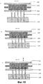
На фиг. 1 чертежей показаны основные компоненты устройства для изготовления щеток, предназначенного для изготовления зубных щеток. Одним из этих компонентов является пресс-форма, состоящая из первой неподвижной части 10 пресс-формы, второй подвижной части 12 пресс-формы и пары дополняющих частей 14a, 14b пресс-формы, вставляемых в выемку 16 первой или второй части 12 пресс-формы. Дополняющие части 14a, 14b пресс-формы присоединены к концам двухзахватного держателя 18, который установлен с возможностью поворотного и возвратно-поступательного смещения на оси 20 вдоль нее. Части 10, 12 и 14a (или 14b) пресс-формы ограничивают (образуют) формообразующую полость 22, имеющую форму корпуса зубной щетки, подлежащего изготовлению путем литья под давлением в пресс-форме. Дополняющие части 14a, 14b пресс-формы имеют поверхность, которая ограничивает полость и соответствует головке зубной щетки и, в частности, стороне головки, от которой после завершения процесса литья под давлением выступают щетинки. Таким образом, части 14a, 14b пресс-формы выполнены с множеством отверстий 24 для вставления пучков, причем эти отверстия проходят сквозь указанные части пресс-формы и выходят в часть 22a полости, образованную в указанных частях пресс-формы. Как можно видеть на фиг. 1, любую одну из дополняющих частей 14a, 14b пресс-формы можно сместить в положение, при котором она входит в выемку 16 части 12 пресс-формы, при этом другая дополняющая часть пресс-формы находится в положении, в котором она готова принять комплект пучков волокон для образования щетинок зубной щетки. In FIG. 1 of the drawings shows the main components of a device for the manufacture of brushes intended for the manufacture of toothbrushes. One of these components is a mold, consisting of a first stationary part 10 of the mold, a second movable part 12 of the mold and a pair of
Подача требуемых комплектов пучков к дополняющим частям 14a, 14b пресс-формы осуществляется устройством для подачи пучков, которое также схематично показано на фиг. 1. Устройство для подачи пучков содержит подвижную транспортирующую (несущую) кассету 30, в которой закреплен комплект трубок 32 для извлечения и перемещения пучков. Трубки 32 удерживаются в транспортирующей кассете 30 так, чтобы обеспечить возможность их относительных смещений в осевых направлениях трубок, но предусмотрен зажимной механизм с зажимной пластиной 34, чтобы зажимать трубки 32 в фиксированных положениях относительно транспортирующей кассеты 30. Схема расположения трубок 32, предназначенных для извлечения и перемещения пучков, в транспортирующей кассете 30 соответствует сетке отверстий 24 для вставки пучков в частях 14a, 14b пресс-формы. Схема расположения комплекта плунжерных элементов 36 также аналогична сетке отверстий 24, и указанный комплект связан с трубками 32, так что плунжерные элементы 36 могут проходить во внутренние каналы, образованные в трубках 32, и выталкивать вперед пучки щетинок, содержащиеся в них. The required bundle sets are supplied to the
Нагревательное устройство 40, например воздуходувка горячего дутья, предназначено для того, чтобы подавать струю горячего воздуха к концам волокон из пучков, вставленных через отверстия 24 и выступающих в часть 22a полости. Нагрев концов волокон выполняют для того, чтобы частично расплавить материал волокон для образования отдельных выпуклостей (утолщений) или, в конце концов, более или менее непрерывной (сплошной) основы из волокнистого материала, которая будет заделана в литьевую массу в процессе выполнения операции литья под давлением. A heating device 40, for example a hot blast blower, is designed to supply a stream of hot air to the ends of the fibers from bundles inserted through
Как видно также на фиг. 1, в качестве необязательного конструктивного элемента предусмотрена подвижная пластина 42, которая применяется как упор для пучков волокон, выталкиваемых через отверстия 24 с помощью плунжерных элементов 36. Пластине 42 может быть придана такая форма, которая обеспечивает желательный профиль пучков щетинок, выступающих из готовой зубной щетки. Если волокна, выступающие в формообразующую полость, имеют какую-либо избыточную длину, они могут быть подрезаны режущим инструментом 44. As can also be seen in FIG. 1, a movable plate 42 is provided as an optional structural element, which is used as an abutment for fiber bundles pushed through
Имеется оптическое контрольное устройство 50, такое, как видеокамера, которое предназначено для контроля отверстий 24 в процессе вставки пучков волокон в отверстия 24 или после указанной вставки. Если какие-либо из пучков отсутствуют, предпринимается соответствующее корректирующее действие. Несмотря на то, что показано оптическое контрольное устройство 50, можно использовать любую другую систему автоматического обнаружения, например, устройство для тактильного обнаружения. There is an optical monitoring device 50, such as a video camera, which is designed to control the
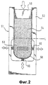
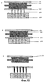
В устройстве для подачи пучков используется контейнер для щетинок, имеющий особую конструкцию. Контейнер для щетинок показан на фиг. 2. Как видно на фиг. 2, контейнер 51 содержит по существу U-образную раму 52, вертикальные стойки которой ограничивают по существу прямоугольное пространство для приема пачки параллельных предварительно обработанных щетинок (или волокон) 54. Гибкая лента 56 охватывает пачку щетинок 54. Верхние концы гибкой ленты 56 удерживаются на внутренних сторонах вертикальных стоек рамы 52. Гибкая лента 56 также имеет по существу U- образную форму с открытым верхним концом, который закрыт прижимным блоком 58. Прижимной блок 58 удерживает щетинки 54 по существу под постоянным давлением. Когда происходит извлечение пучков щетинок из пачки, прижимной блок 58 опускается для компенсации уменьшения объема пачки. Гибкая лента 56 обеспечивает возможность ограниченного бокового смещения пачки щетинок 54 в ее нижней части. Нижняя часть гибкой ленты 56 имеет дополнительную опору в виде трех упругих опорных элементов 60, таких, как пружины сжатия, установленные между наружной поверхностью ленты 56 и участком стенки рамы 52, в котором имеется выемка. The bundle feeder uses a bristle container having a special design. The bristle container is shown in FIG. 2. As seen in FIG. 2, the
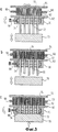
На фиг. 3A, B и C контейнер для щетинок показан в рабочем положении рядом с транспортирующей кассетой 30, имеющей трубки 32 для извлечения и транспортировки пучков. Пластина 62, выполненная со сквозными отверстиями, которые соосны с трубками 32, расположена между транспортирующей кассетой 30 и пачкой щетинок 54. Со стороны, противоположной пластине 62, задние концы щетинок 54 за счет трения входят в контакт с совершающей колебательное движение пластиной 64, колебательное движение которой параллельно плоскости пластины. In FIG. 3A, B and C, the bristle container is shown in the operational position next to the
Транспортирующая кассета 30 содержит размещенные на расстоянии друг от друга переднюю и заднюю стенки с соосными отверстиями, в которые входят трубки 32 с возможностью скольжения. В пространстве, образованном между передней и задней стенками транспортирующей кассеты 30, размещена зажимная пластина 34. Зажимная пластина 34 аналогичным образом выполнена с отверстиями, через которые проходят трубки 32. Обычно трубки 32 могут свободно скользить в транспортирующей кассете 30 в направлении своей длины. Однако когда боковое усилие, которое может создаваться за счет поворота зажимного винта 66, действует на зажимной элемент 34, происходит зажим трубок 32 и их фиксация в заданном положении относительно транспортирующей кассеты 30. The transporting
Как видно также на фиг. 3A, B и C предусмотрен толкающий блок 70. Толкающий блок 70 входит в контакт с задними концами трубок 32 и выполняет неоднократные (повторяющиеся) возвратно-поступательные толкающие ходы, чтобы подать передние концы трубок 32 немного вперед для небольшого проникновения в пачку щетинок 54. На начальной стадии процесса извлечения пучков толкающий блок 70 неоднократно толкает передние концы трубок 32, перемещая их на короткое расстояние порядка 1 или 2 мм в пачку щетинок 54. Некоторые из трубок 32 сразу смогут охватить пучок щетинок, прошедших во внутренний канал трубки, и при этом окружающие щетинки будут раздвинуты передним краем трубки. Когда толкающий блок 70 отходит назад от задних концов трубок 32, те трубки, в которые вошли пучки щетинок 54, останутся своими передними концами в пачке, а остальные трубки вернутся в свое исходное положение, поскольку они не смогли пройти в пачку из-за того, что передние концы щетинок уперлись в них. Как легко можно понять, такое возвратное смещение трубок 32 возможно, поскольку трубки могут свободно смещаться в отверстиях транспортирующей кассеты 30 независимо друг от друга. Чтобы способствовать проникновению трубок 32 в пачку щетинок 54, пластина 64 совершает колебательное движение, так что щетинки немного смещаются в пачке 54 в направлении, поперечном к их длине. As can also be seen in FIG. 3A, B, and C, a
На фиг. 3B показана начальная стадия процесса извлечения пучков, когда две из трубок 32 уже вошли в пачку щетинок 54, охватив соответствующие пучки щетинок, а три другие трубки 32 не вошли в пачку щетинок и вернулись в свои исходные положения. Тем не менее после ограниченного числа толкающих ходов толкающего блока 70 все трубки 32 проникнут на некоторое расстояние в пачку щетинок 54. В этот момент толкающий блок 70 выполняет последний дополнительный ход, тем самым осуществляется полное вталкивание трубок 32 в пачку щетинок 34 до тех пор, пока они не упрутся в концевую пластину 72, заменяющую теперь совершающую колебательное движение пластину 64. Зажимной винт 66 поворачивают таким образом, чтобы он вошел в контакт с зажимной пластиной 34, так что происходит зажим трубок 32 в заданном положении относительно транспортирующей кассеты 30. Толкающий блок 70 отводят, и трубки 32 могут быть вытянуты из пачки щетинок 54, при этом во внутренних каналах трубок 32 остаются пучки щетинок. In FIG. 3B shows the initial stage of the beam extraction process when two of the
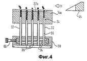
Транспортирующую кассету 30 с трубками 32 и захваченными ими пучками щетинок теперь смещают так, чтобы передние концы трубок 32 оказались выровненными относительно отверстий 24 для вставки пучков в дополняющей части 14a или 14b пресс-формы. Как показано на фиг. 4, плунжерные элементы 36 теперь введены в задние концы трубок 32, чтобы толкать пучки щетинок, содержащиеся в трубках, через отверстия 24 части 14a (или 14b) пресс-формы. Как также видно на фиг. 4, плунжерные элементы 36 можно подать вперед на различную длину, так что наружные концы пучков щетинок окажутся на различной высоте относительно ограничивающего полость участка поверхности части 14а пресс-формы. Если волокна из пучков, выступающие в полость, имеют какую-либо избыточную длину, они могут быть обрезаны, используя режущий инструмент 44. Кроме того, как также видно на фиг. 4, передним концам плунжерных элементов 36 может быть придана такая форма, которая позволяет придать наружным концам пучков желаемый профиль. The
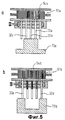
В альтернативном варианте осуществления изобретения, показанном на фиг. 5A и 5B, применяется пара различных толкающих блоков 70a и 70b. Толкающий блок 70a будет выборочно входить в контакт только с первым комплектом трубок, обозначенных поз. 32a, 32d и 32c на фиг. 5A. На последующей операции извлечения пучков толкающий блок 70b будет входить в контакт с остальными трубками 32d и 32e. На первой операции извлечения пучков, изображенной на фиг. 5A, из первого контейнера 51a для щетинок извлекают щетинки 54a первого типа, а на второй операции извлечения пучков, показанной на фиг. 5B, из второго контейнера 51b для щетинок извлекают щетинки 54b второго типа. Как легко можно понять, таким образом можно комбинировать любое число типов щетинок для получения широкого разнообразия зубных щеток. In an alternative embodiment of the invention shown in FIG. 5A and 5B, a pair of different pushing
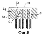
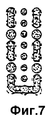
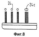
Другой способ комбинирования щетинок аналогичного или различного типа показан на фиг. 6, 7 и 8. Как видно на фиг. 6, часть 14a (или 14b) пресс-формы имеет ряд прямолинейных отверстий 24 для вставки пучков и пару отверстий 24a, 24b, сливающихся в общее выходное отверстие 24c на стороне участка 22a полости. Как показано на фиг. 8, выходное отверстие 24c может иметь вытянутую (удлиненную) форму при виде сверху, что позволяет получить более широкий пучок щетинок в готовой зубной щетке. За счет того, что по меньшей мере два отверстия для вставки пучков сливаются в общее выходное отверстие, можно получить различные типы схем расположения пучков. Пример показан на фиг. 7. Another method for combining bristles of a similar or different type is shown in FIG. 6, 7 and 8. As can be seen in FIG. 6, the
Как показывает фиг. 2, а также фиг. 9, когда пачка щетинок 54 постепенно опустошается и прижимной блок 58 опускается до некоторого уровня, такого как уровень L, показанный на фиг. 2, необходимо пополнить контейнер с волокнами. К этому моменту времени, возможно, уже изготовлено большое количество зубных щеток при использовании одного контейнера для щетинок. В этом случае контейнер для щетинок убирают от устройства подачи пучков и транспортируют к комбинированному устройству для обработки щетинок и повторного наполнения контейнера щетинками, которое показано на фиг.9, в то время как новый полный контейнер для щетинок перемещают к устройству подачи пучков. As shown in FIG. 2 as well as FIG. 9, when the pack of
Устройство, показанное на фиг. 9, содержит ступенчато поворачивающийся диск 80, который имеет ряд расположенных на некотором расстоянии друг от друга вдоль окружной поверхности диска гнезд 82 для размещения щетинок, причем эти гнезда выполнены в периферийной поверхности диска. Устройство 84 подачи необработанных волокон находится в первом положении вокруг диска 80 и предназначено для подачи пачки необработанных волокон в каждое из гнезд 82, проходящих мимо данного устройства спереди от него. Путем ступенчатого поворота диска 80 пачки волокон, содержащиеся в гнездах 82, поворачиваются в заданные положения, соответствующие ряду устройств 86 обработки, на которых свободные концы волокон подвергаются операции шлифования для округления концов волокон. За обрабатывающими устройствами 86 следуют одно или более обрабатывающих устройств 88, которые представляют собой устройства полирования концов волокон. В завершение, пачки с окончательно обработанными волокнами щетинок подаются к устройству 90 сбора, с помощью которого осуществляется повторное наполнение контейнера 51 для щетинок с его верхней открытой стороны, при этом прижимной блок 58 (см. фиг. 2) удален. The device shown in FIG. 9, comprises a stepwise
Устройство по фиг. 9 имеет производительность, значительно превышающую ту, которая необходима для одной пресс-формы типа, показанного на фиг. 1. Таким образом, используя одно комбинированное устройство для обработки щетинок и для наполнения (пополнения) контейнеров щетинками, можно обеспечивать множество установок для литья щеток под давлением вновь заполненными контейнерами со щетинками. The device of FIG. 9 has a productivity significantly higher than that required for one mold of the type shown in FIG. 1. Thus, using a single combined device for processing bristles and for filling (replenishing) containers with bristles, it is possible to provide many installations for molding brushes under pressure with newly filled containers with bristles.
Тем не менее, в альтернативном варианте осуществления изобретения устройство, аналогичное показанному на фиг. 9, может быть встроено в устройство для подачи пучков машины, изображенной на фиг. 1. However, in an alternative embodiment of the invention, a device similar to that shown in FIG. 9 can be integrated in the bundle feeder of the machine of FIG. 1.
Предпочтительный вариант осуществления устройства для извлечения пучков будет описан со ссылкой на фиг. 10 и 11. A preferred embodiment of the beam extraction device will be described with reference to FIG. 10 and 11.
На фиг. 10A, которая в основном соответствует фиг. 3A, рассмотренной выше, трубки 132, предназначенные для извлечения пучков, жестко закреплены в держателе 130. Пластина 162 удерживается с возможностью скольжения на держателе 130 так, что эта пластина 162, которая имеет сквозные отверстия для извлекающих трубок 132, может скользить относительно этих трубок таким образом, как видно из чертежей. В положении, показанном на фиг. 10A, пластина 162 упирается в передние концы щетинок 154, содержащихся в контейнере 151 для щетинок. Как и в ранее описанном варианте осуществления изобретения, задние концы щетинок 154 введены в контакт с совершающей колебательное движение пластиной 164. Передние края извлекающих трубок 132 выровнены в плоскости пластины 162. In FIG. 10A, which basically corresponds to FIG. 3A described above, the
Как видно на фиг. 10B, держатель 130 с извлекающими трубками 132 теперь подан вперед так, что передние концы извлекающих трубок 132 проникают в пачку щетинок на короткое расстояние, которое представляет собой малую часть длины щетинки, при этом пластина 164 непрерывно колеблется. Пластина 162 отведена от передних концов извлекающих трубок 132 путем скольжения по трубкам. Величина начального проникновения извлекающих трубок 132 в пачку щетинок 154 зависит от длины и толщины щетинок. При изготовлении зубных щеток соответствующее расстояние составляет от 2 до 3 мм. As seen in FIG. 10B, the
Извлекающие трубки 132 остаются в этом положении в течение короткого периода времени, например, от 0.5 до 5 секунд, в зависимости от размера и свойств щетинок, при этом пластина 164 продолжает колебаться. Как легко можно понять, на начальной стадии проникновения извлекающих трубок в пачку щетинок некоторые из щетинок будут упираться в передние края трубок и изгибаться. Тем не менее благодаря продолжающемуся колебательному движению пластины 164 большая часть щетинок окажется выровненной относительно отверстий в извлекающих трубках или внутри данных отверстий, или снаружи их. The
Чтобы гарантировать то, что все щетинки надлежащим образом выровнены и что не осталось никаких щетинок, упершихся в передние края извлекающих трубок, пластина 164 теперь совершает комбинированное колебательное (в горизонтальном направлении) и постукивающее (в вертикальном направлении) движение, как видно на фиг. 10C. Комбинированное колебательное и постукивающее движение пластины 104 выполняется в течение короткого периода времени, например в течение нескольких секунд. In order to ensure that all the bristles are properly aligned and that there are no bristles to rest on the front edges of the extraction tubes, the
Когда все щетинки выровнены надлежащим образом внутри или снаружи извлекающих трубок, колебательное и постукивающее движение пластины 164 прекращается, и эту пластину заменяют на противодействующую пластину 172, как видно на фиг. 10D. Противодействующая пластина 172 имеет гладкую выравнивающую поверхность, приложенную к задним концам щетинок 154 в пачке. When all the bristles are properly aligned inside or outside the extraction tubes, the oscillating and tapping movement of the
Теперь осуществляют дальнейшую подачу извлекающих трубок 132 вперед в пачку щетинок до тех пор, пока передние края трубок не упрутся в пластину 172 на последнем ходе извлечения, как показано на фиг. 10E. Now, the
После этого извлекающие трубки вытягивают из пачки щетинок с пучками щетинок, захваченными ими, как видно на фиг. 10F. Как также видно на этой фигуре, пластина 162 смещается вместе с держателем 130, оставляя передние концы щетинок 154 открытыми. After that, the extraction tubes are pulled from the bundle of bristles with tufts of bristles captured by them, as can be seen in FIG. 10F. As also seen in this figure, the
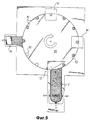
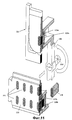
Устройство для извлечения пучков, показанное на фиг. 11, функционирует описанным выше образом. В данном варианте осуществления устройства для извлечения щетинок пара держателей 130a, 130b удерживается с возможностью смещения в двуруком захвате 200 для держателей, который может смещаться как вокруг горизонтальной оси 210, так и вдоль этой оси. Пока держатель 130а находится спереди от контейнера 151 для щетинок, чтобы заполнить свои извлекающие трубки пучками щетинок, другой держатель 130b находится спереди от пластины 220, предназначенной для сбора щетинок, которая имеет множество выполненных в ней групп отверстий 222 для размещения пучков. Более точно, передние концы трубок 132b, предназначенных для извлечения пучков, выровнены относительно одной группы отверстий 222 для размещения пучков. Чтобы переместить пучки щетинок, содержащиеся в извлекающих трубках 132b, в отверстия 222 для размещения пучков, имеющиеся в собирающей пластине 220, в задние концы извлекающих трубок 132b вводят плунжерные элементы 136. The beam extraction device shown in FIG. 11 operates in the manner described above. In this embodiment, the device for extracting the bristles of the pair of
В еще одном варианте осуществления изобретения плунжерные элементы 136 смещаются с извлекающими трубками 132. Таким образом, относительное смещение осуществляется только для того, чтобы переместить извлеченные пучки щетинок в сквозные отверстия в пластине 220, предназначенной для сбора пучков. In yet another embodiment, the
Когда комплект пучков перемещен из держателя 130b в группу отверстий 222 для размещения пучков, собирающую пластину 220 смещают в заданное положение, чтобы подать новую группу отверстий 222 для размещения пучков к извлекающим трубкам 132a держателя 130a, который после извлечения следующего комплекта пучков из контейнера 151 для щетинок перемещен в положение перед собирающей пластиной 220 за счет комбинированного поворота и осевого смещения захвата 200 для держателей. Одновременно происходит смещение пустых трубок 132b, предназначенных для извлечения пучков и имеющихся в держателе 130b, в положение перед контейнером 151 для щетинок, чтобы они извлекли следующий комплект пучков щетинок. When the bundle set is moved from the
Когда все группы отверстий 222 для размещения пучков в собирающей плите 220 будут заполнены пучками щетинок, извлеченными из одного и того же контейнера 151 для щетинок или из разных контейнеров для щетинок, собирающую пластину 220 смещают к пресс-форме таким образом, что отверстия для размещения пучков оказываются спереди от соответствующих отверстий для вставки пучков пресс-формы. Естественно, в данном варианте осуществления изобретения пресс-форма имеет часть пресс-формы, конфигурация которой соответствует конфигурации собирающей пластины 220 для одновременного изготовления множества зубных щеток путем литья под давлением. Перемещение пучков из собирающей пластины 220 в отверстия для вставки в части пресс-формы выполняется так же, как и в варианте осуществления изобретения по фиг. 1, путем ввода плунжерных элементов в задние концы отверстий 222 для размещения пучков, так что пучки будут обязательно вытолкнуты из отверстий 222 и введены в отверстия для вставки пучков в части пресс-формы. When all groups of
Claims (16)
Applications Claiming Priority (3)
| Application Number | Priority Date | Filing Date | Title |
|---|---|---|---|
| GB9406226A GB2287901B (en) | 1994-03-29 | 1994-03-29 | A brush making machine |
| GB9406226.2 | 1994-03-29 | ||
| PCT/EP1995/001150 WO1995026149A1 (en) | 1994-03-29 | 1995-03-28 | A brush-making machine |
Publications (2)
| Publication Number | Publication Date |
|---|---|
| RU96119756A RU96119756A (en) | 1998-11-20 |
| RU2124305C1 true RU2124305C1 (en) | 1999-01-10 |
Family
ID=10752703
Family Applications (1)
| Application Number | Title | Priority Date | Filing Date |
|---|---|---|---|
| RU96119756/12A RU2124305C1 (en) | 1994-03-29 | 1995-03-28 | Brush manufacture apparatus and bristle bundles extraction method |
Country Status (7)
| Country | Link |
|---|---|
| KR (1) | KR100353980B1 (en) |
| CO (1) | CO4410214A1 (en) |
| HK (1) | HK1009716A1 (en) |
| IN (1) | IN191066B (en) |
| MX (1) | MX9604407A (en) |
| MY (1) | MY111778A (en) |
| RU (1) | RU2124305C1 (en) |
Cited By (1)
| Publication number | Priority date | Publication date | Assignee | Title |
|---|---|---|---|---|
| RU2500319C2 (en) * | 2000-03-16 | 2013-12-10 | Джиллет Кэнада Компани | Toothbrush |
Families Citing this family (1)
| Publication number | Priority date | Publication date | Assignee | Title |
|---|---|---|---|---|
| KR102290562B1 (en) | 2020-12-23 | 2021-08-17 | 유문근 | Injection mold withdrawal device |
-
1995
- 1995-03-16 IN IN479DE1995 patent/IN191066B/en unknown
- 1995-03-27 MY MYPI95000753A patent/MY111778A/en unknown
- 1995-03-28 KR KR1019960705399A patent/KR100353980B1/en not_active IP Right Cessation
- 1995-03-28 MX MX9604407A patent/MX9604407A/en not_active IP Right Cessation
- 1995-03-28 RU RU96119756/12A patent/RU2124305C1/en not_active IP Right Cessation
- 1995-03-29 CO CO95012862A patent/CO4410214A1/en unknown
-
1998
- 1998-09-07 HK HK98110511A patent/HK1009716A1/en not_active IP Right Cessation
Cited By (1)
| Publication number | Priority date | Publication date | Assignee | Title |
|---|---|---|---|---|
| RU2500319C2 (en) * | 2000-03-16 | 2013-12-10 | Джиллет Кэнада Компани | Toothbrush |
Also Published As
| Publication number | Publication date |
|---|---|
| IN191066B (en) | 2003-09-13 |
| HK1009716A1 (en) | 1999-06-04 |
| MX9604407A (en) | 1997-07-31 |
| CO4410214A1 (en) | 1997-01-09 |
| KR100353980B1 (en) | 2003-01-24 |
| MY111778A (en) | 2000-12-30 |
| KR970702001A (en) | 1997-05-13 |
Similar Documents
| Publication | Publication Date | Title |
|---|---|---|
| US5728408A (en) | Molding apparatus with a tuft feeder for making a brush | |
| KR100362482B1 (en) | Brush manufacturing device | |
| US5344218A (en) | Apparatus for producing bristle bundles | |
| KR102104378B1 (en) | Feeder for supplying a batch of bristles to the bristle filament cassette | |
| RU2124305C1 (en) | Brush manufacture apparatus and bristle bundles extraction method | |
| TW201724990A (en) | Device and method for producing bristle arrays for brushes | |
| RU96119756A (en) | DEVICE FOR MAKING BRUSHES AND METHOD FOR REMOVING BRUSH BUNCHES | |
| EP0088469B1 (en) | Arrangement for filling cassettes with fibres | |
| KR102068542B1 (en) | Automatic capturing device for end of string | |
| US6880896B2 (en) | Device for manufacturing brush products | |
| KR100683533B1 (en) | Apparatus for arraying toothbrush head plate | |
| TWI803708B (en) | Brush plugging machine and method for plugging holes | |
| TWI791560B (en) | Verfahren und vorrichtung zum bearbeiten eingedrehter buersten | |
| JPH10257925A (en) | Manufacture of brush | |
| TW202344204A (en) | Device for compacting bristle bundles, bristle product production machine, and method for compacting bristle bundles | |
| JP2001513685A (en) | Hair transplanting method and device |
Legal Events
| Date | Code | Title | Description |
|---|---|---|---|
| MM4A | The patent is invalid due to non-payment of fees |
Effective date: 20040329 |