RU2121172C1 - Device and method for voice signal processing - Google Patents
Device and method for voice signal processing Download PDFInfo
- Publication number
- RU2121172C1 RU2121172C1 RU96122986A RU96122986A RU2121172C1 RU 2121172 C1 RU2121172 C1 RU 2121172C1 RU 96122986 A RU96122986 A RU 96122986A RU 96122986 A RU96122986 A RU 96122986A RU 2121172 C1 RU2121172 C1 RU 2121172C1
- Authority
- RU
- Russia
- Prior art keywords
- specified
- pulses
- amplitude
- target vector
- pulse
- Prior art date
Links
Images

Classifications
-
- G—PHYSICS
- G10—MUSICAL INSTRUMENTS; ACOUSTICS
- G10L—SPEECH ANALYSIS OR SYNTHESIS; SPEECH RECOGNITION; SPEECH OR VOICE PROCESSING; SPEECH OR AUDIO CODING OR DECODING
- G10L19/00—Speech or audio signals analysis-synthesis techniques for redundancy reduction, e.g. in vocoders; Coding or decoding of speech or audio signals, using source filter models or psychoacoustic analysis
- G10L19/04—Speech or audio signals analysis-synthesis techniques for redundancy reduction, e.g. in vocoders; Coding or decoding of speech or audio signals, using source filter models or psychoacoustic analysis using predictive techniques
- G10L19/08—Determination or coding of the excitation function; Determination or coding of the long-term prediction parameters
- G10L19/10—Determination or coding of the excitation function; Determination or coding of the long-term prediction parameters the excitation function being a multipulse excitation
- G10L19/113—Regular pulse excitation
-
- G—PHYSICS
- G10—MUSICAL INSTRUMENTS; ACOUSTICS
- G10L—SPEECH ANALYSIS OR SYNTHESIS; SPEECH RECOGNITION; SPEECH OR VOICE PROCESSING; SPEECH OR AUDIO CODING OR DECODING
- G10L19/00—Speech or audio signals analysis-synthesis techniques for redundancy reduction, e.g. in vocoders; Coding or decoding of speech or audio signals, using source filter models or psychoacoustic analysis
- G10L19/04—Speech or audio signals analysis-synthesis techniques for redundancy reduction, e.g. in vocoders; Coding or decoding of speech or audio signals, using source filter models or psychoacoustic analysis using predictive techniques
- G10L19/08—Determination or coding of the excitation function; Determination or coding of the long-term prediction parameters
- G10L19/10—Determination or coding of the excitation function; Determination or coding of the long-term prediction parameters the excitation function being a multipulse excitation
Landscapes
- Engineering & Computer Science (AREA)
- Computational Linguistics (AREA)
- Signal Processing (AREA)
- Health & Medical Sciences (AREA)
- Audiology, Speech & Language Pathology (AREA)
- Human Computer Interaction (AREA)
- Physics & Mathematics (AREA)
- Acoustics & Sound (AREA)
- Multimedia (AREA)
- Compression, Expansion, Code Conversion, And Decoders (AREA)
- Monitoring And Testing Of Transmission In General (AREA)
- Mobile Radio Communication Systems (AREA)
Abstract
Description
Настоящее изобретение имеет отношение главным образом к созданию системы обработки речевого сигнала и, в частности, многоимпульсной системы анализа. The present invention relates mainly to the creation of a speech signal processing system and, in particular, a multi-pulse analysis system.
Обработка речевого сигнала широко известна и часто применяется для сжатия поступающего речевого сигнала, как для его хранения, так и для последующей передачи. Обработка речевого сигнала обычно связана с делением входного речевого сигнала на блоки данных (кадры), с последующим анализом каждого блока данных для нахождения его компонентов. Затем полученные компоненты используются как для хранения, так и для последующей передачи. The processing of a speech signal is widely known and is often used to compress an incoming speech signal, both for its storage and for subsequent transmission. The processing of a speech signal is usually associated with dividing the input speech signal into data blocks (frames), followed by analysis of each data block to find its components. Then, the obtained components are used both for storage and for subsequent transmission.
Обычно анализатор кадра определяет кратковременные и долговременные характеристики речевого сигнала. Затем анализатор кадра может найти один или оба кратко- или долговременных компонента или "вклада" речевого сигнала. Например, анализ с линейным коэффициентом предсказания (LPC) позволяет получить кратковременные характеристики и вклады, а анализ основного тона и прогнозирование позволяют получить долговременные характеристики и долговременные вклады (компоненты). Typically, a frame analyzer determines the short-term and long-term characteristics of a speech signal. The frame analyzer can then find one or both short- or long-term components or the “contribution” of the speech signal. For example, analysis with linear prediction coefficient (LPC) allows you to get short-term characteristics and contributions, and pitch analysis and prediction allows you to get long-term characteristics and long-term contributions (components).
Обычно оба или один из долго- или кратковременных компонентов прогнозирования вычитают из входного кадра, после чего остается вектор цели, форму которого следует определить. Такое определение параметров (вектора цели) может быть осуществлено при помощи многоимпульсного анализа (МРА), который подробно описан в разделе 6. 4. 2. книги Цифровая обработка речи, синтез и распознавание, автора Садаоки Фуруи, издательство Марсель Деккер Инк., Нью-Йорк, 1989 г. Typically, both or one of the long- or short-term prediction components is subtracted from the input frame, after which the target vector remains, the shape of which should be determined. Such a determination of the parameters (target vector) can be carried out using multi-pulse analysis (MRA), which is described in detail in
При проведении МРА вектор цели, который образован множеством выборок, моделируется множеством импульсов (или пиков) одинаковой амплитуды, которые имеют различное местоположение и разные знаки (положительный или отрицательный). Для выбора каждого импульса его помещают в каждое местоположение выборки и находят отклик (эффект) при пропускании этого импульса через фильтр, параметры которого определены коэффициентами LPC. Выбирают импульс, который наиболее близко совпадает с вектором цели, и удаляют его отклик из вектора цели, в результате чего вырабатывается новый вектор цели. Процесс продолжают до получения заданного числа импульсов. Для целей хранения или передачи, результатом МРА анализа является набор импульсов местоположения и квантованные значения усиления. When conducting MPA, the target vector, which is formed by many samples, is modeled by many pulses (or peaks) of the same amplitude, which have different locations and different signs (positive or negative). To select each pulse, it is placed at each location of the sample and the response (effect) is found when this pulse is passed through a filter whose parameters are determined by the LPC coefficients. The impulse that most closely matches the target vector is selected and its response is removed from the target vector, as a result of which a new target vector is generated. The process continues until a given number of pulses is obtained. For storage or transmission purposes, the result of an MPA analysis is a set of location pulses and quantized gain values.
Усиление обычно определяют по первому импульсу, который найден. Это усиление затем используют для остальных импульсов. К несчастью величина усиления для первого импульса не всегда является показательной для средней величины усиления вектора цели, в результате чего совпадение с вектором цели не всегда точное. The gain is usually determined by the first pulse that is found. This gain is then used for the remaining pulses. Unfortunately, the gain for the first impulse is not always indicative of the average gain of the target vector, as a result of which the coincidence with the target vector is not always accurate.
В связи с изложенным, задачей настоящего изобретения является создание улучшенной системы анализа речевого сигнала. В соответствии с первым вариантом осуществления настоящего изобретения, указанная система включает в себя кратковременный анализатор, генератор вектора цели и блок многоимпульсного анализатора с максимальным правдоподобием квантования (MLQ). Кратковременный анализатор производит определение кратковременных характеристик входного речевого сигнала. Генератор вектора цели вырабатывает вектор цели по меньшей мере из определенного входного сигнала. Блок MLQ многоимпульсного анализа оперирует над результирующим вектором цели. In connection with the foregoing, the object of the present invention is to provide an improved speech signal analysis system. According to a first embodiment of the present invention, said system includes a short-term analyzer, a target vector generator, and a maximum pulse quantization (MLQ) multi-pulse analyzer unit. The short-term analyzer determines the short-term characteristics of the input speech signal. The target vector generator generates a target vector from at least a certain input signal. The multipulse analysis MLQ block operates on the resulting target vector.
Блок MLQ многоимпульсного анализа обычно производит определение уровня единичного усиления для многоимпульсной последовательности и осуществляет МРА с единичным усилением несколько раз, причем всякий раз с различным уровнем усиления. При этом уровни усиления находятся в диапазоне выше и ниже начального уровня усиления. Результирующие импульсы могут быть положительными или отрицательными. The multipulse analysis MLQ unit usually determines the unit gain level for the multipulse sequence and performs MPA with unit gain several times, each time with a different gain level. The gain levels are in the range above and below the initial gain level. The resulting impulses can be positive or negative.
Аналогично другим применениям с нахождением максимального правдоподобия, производят измерение качества полученного результата (в данном случае путем минимизации энергии вектора ошибки, который определяют как разницу между вектором цели и вектором оценки, полученным фильтрацией импульсной последовательности единичного усиления через распознающий фильтр со взвешиванием). Импульсная последовательность, которая минимизирует энергию вектора ошибки и его соответствующий уровень усиления (или коэффициент для уровня усиления), является выходным сигналом блока MLQ многоимпульсного анализа. Similarly to other applications with finding the maximum likelihood, the quality of the result is measured (in this case, by minimizing the energy of the error vector, which is defined as the difference between the target vector and the estimation vector obtained by filtering the unit amplification pulse sequence through a weighting recognition filter). The pulse sequence, which minimizes the energy of the error vector and its corresponding gain level (or coefficient for the gain level), is the output signal of the multi-pulse analysis unit MLQ.
В соответствии с альтернативным вариантом осуществления настоящего изобретения, система включает в себя долговременный анализатор прогнозирования, а блок MLQ многоимпульсного анализа заменен блоком многоимпульсного анализа пачки импульсов. В соответствии с этим вариантом в блоке многоимпульсного анализа пачки импульсов используется смещение основного тона от долговременного анализатора для создания пачки импульсов равной амплитуды и одинакового знака, причем каждый импульс имеет смещение основного тона от предыдущих импульсов в пачке. Блок многоимпульсного анализа позволяет получить на его выходе сигнал, отображающий последовательность пачек импульсов, которая включает в себя положительные и отрицательные пачки импульсов, наилучшим образом отображающие вектор цели. According to an alternative embodiment of the present invention, the system includes a long-term prediction analyzer, and the multi-pulse analysis unit MLQ is replaced with a multi-pulse pulse analysis unit. In accordance with this embodiment, in the multi-pulse analysis unit of the pulse train, the pitch shift from the long-term analyzer is used to create a pulse train of equal amplitude and same sign, with each pulse having a pitch shift from previous pulses in the packet. The multi-pulse analysis unit allows you to receive a signal at its output that displays a sequence of bursts of pulses, which includes positive and negative bursts of pulses that best represent the target vector.
В соответствии с еще одним альтернативным вариантом осуществления настоящего изобретения система включает в себя блок MLQ многоимпульсного анализа пачки импульсов, который объединяет в себе операции в соответствии с двумя предыдущими вариантами осуществления настоящего изобретения. Другими словами, задают диапазон усилений и для каждого усиления находят пачки импульсов. Выходным сигналом является последовательность, которая наиболее близко совпадает с вектором цели. In accordance with yet another alternative embodiment of the present invention, the system includes a multi-pulse burst analysis MLQ unit that combines operations in accordance with two previous embodiments of the present invention. In other words, the range of amplifications is set, and for each gain, bursts of pulses are found. The output signal is the sequence that most closely matches the target vector.
В соответствии с еще одним последним альтернативным вариантом осуществления настоящего изобретения, производят сравнение выходных сигналов блоков максимального правдоподобия и многоимпульсного анализа пачки импульсов; последовательность, которая наиболее близко совпадает с вектором цели, будет выходным сигналом. In accordance with another last alternative embodiment of the present invention, the output signals of the maximum likelihood blocks and the multi-pulse analysis of a pulse train are compared; the sequence that most closely matches the target vector will be the output.
Настоящее изобретение может быть более полно понятно и оценено из последующего подробного его описания, приведенного со ссылкой на чертежи. The present invention can be more fully understood and appreciated from the following detailed description given with reference to the drawings.
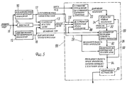
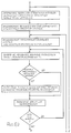
На фиг. 1 показана структурная схема, иллюстрирующая первый вариант осуществления системы обработки речевого сигнала в соответствии с настоящим изобретением. In FIG. 1 is a block diagram illustrating a first embodiment of a speech signal processing system in accordance with the present invention.
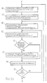
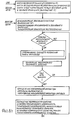
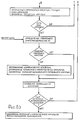
На фиг. 2 показана блок-схема, иллюстрирующая работу многоимпульсного блока, входящего в систему фиг. 1, в котором используется квантование с максимальным правдоподобием (MP-MLQ). In FIG. 2 is a flowchart illustrating the operation of the multi-pulse unit included in the system of FIG. 1, which uses maximum likelihood quantization (MP-MLQ).
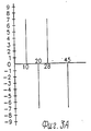
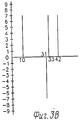
На фиг. 3A и 3B приведены графики, полезные для понимания работы блока фиг. 2. In FIG. 3A and 3B are graphs useful for understanding the operation of the block of FIG. 2.
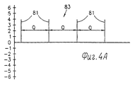
На фиг. 4A и 4B приведены графики, описывающие импульсные пачки и многоимпульсный анализ с использованием импульсных пачек, соответственно. In FIG. 4A and 4B are graphs describing impulse bursts and multipulse analysis using impulse bursts, respectively.
На фиг. 5 показана структурная схема, иллюстрирующая второй вариант осуществления системы обработки речевого сигнала в соответствии с настоящим изобретением, в котором используются импульсные пачки. In FIG. 5 is a block diagram illustrating a second embodiment of a speech signal processing system in accordance with the present invention, using pulse trains.
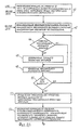
На фиг. 6 показана блок-схема, иллюстрирующая работу многоимпульсного блока анализа пачек импульсов, входящего в систему фиг. 5. In FIG. 6 is a flowchart illustrating the operation of the multi-pulse burst analysis unit included in the system of FIG. 5.
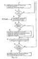
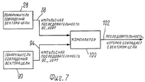
На фиг. 7 показана структурная схема, иллюстрирующая третий вариант, в котором производится сравнение выходных сигналов систем, показанных на фиг. 1 и 5. In FIG. 7 is a block diagram illustrating a third embodiment in which the output signals of the systems shown in FIG. 1 and 5.
Обратимся теперь к рассмотрению фиг. 1, 2, 3A и 3B, на которых показан первый вариант осуществления настоящего изобретения. Система обработки речевого сигнала в соответствии с настоящим изобретением включает в себя по меньшей мере один анализатор кратковременного прогнозирования 10, один анализатор долговременного прогнозирования 12, генератор вектора цели 13 и блок 14 многоимпульсного анализа с использованием квантования с максимальным правдоподобием (MP-MLQ). Turning now to the consideration of FIG. 1, 2, 3A and 3B, showing a first embodiment of the present invention. The speech signal processing system of the present invention includes at least one short-
Анализатор кратковременного прогнозирования 10 получает по входной линии 16 входной кадр речевого сигнала, образованный множеством оцифрованных речевых выборок. Обычно имеется 240 речевых выборок на кадр, причем кадры часто разделены на множество субкадров. Обычно используют 4 субкадра, каждый из которых имеет длину 60 речевых выборок. Входной кадр может представлять собой как исходный речевой сигнал, так и обработанную его версию. The short-
Анализатор кратковременного прогнозирования 10 получает по входной линии 16 входной кадр и выдает по выходной линии 17 кратковременные характеристики входного кадра. В соответствии с одним из вариантов анализатор 10 осуществляет линейный прогнозирующий анализ, в результате которого получают линейные коэффициенты прогнозирования (LPC), которые характеризуют входной кадр. The short-
Для целей настоящего изобретения анализатор 10 может осуществлять любой тип LPC анализа. Например, LPC анализ может быть осуществлен в соответствии с описанным в главе 6. 4. 2. книги Цифровая обработка речи, синтез и распознавание следующим образом: к окну из 180 выборок, центрированных на субкадре, прикладывается окно Хамминга (Hamming). Вырабатываются коэффициенты LPC десятого порядка с использованием рекурсивного метода Дурбина (Durbin). Процесс повторяют для каждого субкадра. For the purposes of the present invention,
Анализатор долговременного прогнозирования 12 может представлять собой устройство долговременного прогнозирования любого типа, которое работает с входными кадрами, поступающими по линии 16. Анализатор долговременного прогнозирования 12 производит анализ множества субкадров входного кадра для определения значения основного тона речевого сигнала внутри каждого субкадра, причем значение основного тона определяется как ряд выборок, после которых речевой сигнал приблизительно повторяет себя. Значения основного тона обычно лежат в диапазоне от 20 до 146, причем 20 отображает речь высокого тона, а 146 отображает речь низкого тона. The long-
Например, для каждых двух субкадров оценка основного тона может быть найдена максимизацией нормализованной функции кросс-корреляции субкадров s (n) в следующем виде:
![]()
В этом примере долговременный анализатор 12 выбирает коэффициент i, который максимизирует кросс-корреляцию C_ i в качестве значения основного тона для двух субкадров.For example, for every two subframes, a pitch estimate can be found by maximizing the normalized cross-correlation function of the subframes s (n) as follows:
![]()
In this example, the long-
После определения долговременным анализатором 12 основного тона этот основной тон используется для определения информации долговременного прогнозирования для субкадров, которая выдается по выходной линии 18. After determining the pitch by the long-
На генератор вектора цепи 13 поступают выходные сигналы долговременного анализатора 12 и кратковременного анализатора 10, также как и входной кадр от входной линии 16 через задержку 19. При поступлении указанных сигналов генератор 13 вырабатывает вектор цели из по меньшей мере одного субкадра входного кадра. Кратко- и долговременная информация может по желанию использоваться или не использоваться. Задержка 19 обеспечивает соответствие поступающего на генератор 13 входного кадра выходным сигналам анализаторов 10 и 12. На выходную линию 26 генератора 13 вектора цели, которая соединена с блоком MP-MLQ 14, подается выходной сигнал вектора цели. Вход блока MP-MLQ 14 обычно также соединен с выходной линией 17, на которой имеется кратковременный сигнал, вырабатываемый анализатором 10. Следует иметь в виду, что безо всякой потери общей применимости вектор цели блока MP-MLQ 14 может быть получен любым другим желательным образом. The output of the vector of the
В соответствии с первым предпочтительным вариантом осуществления настоящего изобретения блок MP-MLQ 14 включает в себя устройство 20 определения местоположения начального импульса, устройство 22 определения диапазона усиления, селектор уровня усиления 24, устройство 25 определения импульсной последовательности, обнаружитель совпадения вектора цели 28 и, опционно, кодирующее устройство 30. Конкретные операции, осуществляемые элементами 20 - 30, иллюстрируются на фиг. 2 и подробно описаны ниже. Далее следует описание работы блока 14. According to a first preferred embodiment of the present invention, the MP-MLQ block 14 includes an initial
На вход устройства 20 определения местоположения начального импульса по выходным линиям 17 и 26 поступают выходные сигналы генератора 13 вектора цели и кратковременного анализатора 10 соответственно. Устройство 20 производит определение местоположения в выборке первого импульса, в соответствии с техникой многоимпульсного анализа. The
На вход устройства 22 определения диапазона усиления с выхода устройства 20 поступает первый импульс; устройство 20 производит определение как амплитуды первого импульса, так и диапазона квантованных уровней усиления в окрестности абсолютного значения найденной амплитуды. Размер шага, именуемый MLQ_STEPS, для перемещения через диапазон квантованных уровней усиления, обычно имеет значение 3 раздельных уровня усиления. Размер шага MLQ_STEPS не определяется блоком MP-MLQ 14. The input of the
На вход селектора уровня усиления 24 поступает диапазон усиления, выработанный устройством 22 определения диапазона усиления; устройство 24 производит перемещение внутри диапазона усиления и выбирает значения усиления. На его выходе на линии 32 получают текущий уровень усиления, для которого должна быть определена последовательность импульсов равной амплитуды. At the input of the gain level selector 24, a gain range is generated by the gain
На вход устройства 25 определения импульсной последовательности по линии 26 поступает вектор цели и по линии 32 текущий уровень усиления; устройство 25 получает из них с использованием техники многоимпульсного анализа, описанной ниже, импульсную последовательность (как с положительными, так и с отрицательными импульсами), которая совпадает с вектором цели. Импульсная последовательность представляет собой ряд положительных и отрицательных импульсов, которые имеют текущий уровень усиления. At the input of the pulse sequence determination device 25, a target vector is received along
На вход обнаружителя совпадения вектора цели 28 по выходной линии 34 поступает выходной сигнал импульсной последовательности устройства 25 и по выходной линии 26 вектор цели. Устройство 28 определяет качество совпадения с использованием критерия типа максимального правдоподобия. Так как имеется диапазон уровней усиления, то устройство 28 подает сигнал управления на селектор 24 уровня усиления для выбора следующего уровня усиления. Этот сигнал показан стрелкой 36. Для каждого значения усиления обнаружитель совпадения 28 определяет качество совпадения и сохраняет параметры совпадения (коэффициент усиления и импульсную последовательность) только в том случае, если обеспечивается меньшее значение критерия, чем при предыдущем совпадении. At the input of the detector of coincidence of the
После того как селектор усиления 24 осуществит перебор всех значений усиления, коэффициент усиления и импульсная последовательность, которые запомнены в обнаружителе совпадения 28, будут иметь ближайшее совпадение с вектором цели. После этого обнаружитель совпадения 28 передает запомненную импульсную последовательность и коэффициент усиления по выходной линии 38 на опционное кодирующее устройство 30. Следует иметь в виду, что путем определения импульсной последовательности для каждого из нескольких уровней усиления, MP-MLQ блок 14 может выбрать такую последовательность, которая наиболее близко совпадает с вектором цели. After the gain selector 24 enumerates all the gain values, the gain and pulse sequence, which are stored in the
Опционное кодирующее устройство 30 производит кодирование выходной импульсной последовательности и коэффициента усиления для хранения и передачи.
Конкретные операции MP-MLQ блока 14 отображены на фиг. 2. В шаге инициализации 40 блок 14 вырабатывает следующие сигналы:
а) весовая функция (импульсная характеристика) h[n] для входного кадра из кратковременных характеристик a-i, которая определена как
h[n] = Σa-i*h[n-i]+δ[n]; 0≤n≤N-1; 1≤i≤P; (2)
h[-n] = 0, n = 1...P,
где P представляет собой число кратковременных характеристик, а N представляет собой число выборок речевого сигнала в субкадре.Specific MP-MLQ operations of block 14 are shown in FIG. 2. In the
a) the weight function (impulse response) h [n] for the input frame from the short-term characteristics a - i, which is defined as
h [n] = Σa - i * h [ni] + δ [n]; 0≤n≤N-1; 1≤i≤P; (2)
h [-n] = 0, n = 1 ... P,
where P is the number of short-term characteristics, and N is the number of samples of the speech signal in the subframe.
б) результат автокорреляции r-hh [l] весовой функции для каждого положения выборки в следующем виде:
r-hh[l] = Σh[n]*h[n-l]; 0≤l≤N-1; 1≤n≤N-1; (3)
в) результат кросс-корреляции r-th [l] между весовой функцией h [n] и вектором цели t[n] для каждого положения выборки в следующем виде:
r-th[l] = Σt[n]*h[n-l]; 0≤l≤N-1; 1≤n≤N-1. (4)
Следует иметь в виду, что весовая функция является функцией кратковременных характеристик a-i, которые поступают по линии 17 от анализатора 10. Весовая функция, которая вырабатывается при шаге инициализации 40, соответствует упомянутому выше анализу LPC Дурбина.b) the result of autocorrelation r - hh [l] of the weight function for each position of the sample in the following form:
r - hh [l] = Σh [n] * h [nl]; 0≤l≤N-1; 1≤n≤N-1; (3)
c) the result of cross-correlation r - th [l] between the weight function h [n] and the target vector t [n] for each position of the sample in the following form:
r - th [l] = Σt [n] * h [nl]; 0≤l≤N-1; 1≤n≤N-1. (4)
It should be borne in mind that the weight function is a function of the short-term characteristics a - i, which are received via
В MP-MLQ блоке 14 используется локальный критерий LC-kj[l] для определения величины квантования для каждого положения выборки l, каждого импульса k и каждого уровня усиления j. Как будет показано далее, уровень локального критерия зависит от значения к (то есть от числа уже определенных импульсов).MP-MLQ block 14 uses the local criterion LC - kj [l] to determine the quantization value for each sample position l, each pulse k, and each gain level j. As will be shown below, the level of the local criterion depends on the value of k (i.e., on the number of impulses already determined).
В шаге 42 локальный критерий LC-O, j[l] для определения характеристик первого импульса инициирован функцией кросс- корреляции r-th[l] в следующем виде:
LC-O[l] = LC-O, j[l] = r-th[l], 0 ≤ l ≤ N-1, j-min ≤ j ≤ j-max. (5)
Максимальное локальное значение локального критерия установлено также для некоторых отрицательных значений. Коэффициент положения l также инициирован для 0.In step 42, the local criterion LC - O, j [l] for determining the characteristics of the first pulse is initiated by the cross-correlation function r - th [l] in the following form:
LC - O [l] = LC - O, j [l] = r - th [l], 0 ≤ l ≤ N-1, j - min ≤ j ≤ j - max. (5)
The maximum local value of the local criterion is also established for some negative values. The position coefficient l is also triggered for 0.
При осуществлении операций (шагов) 44 - 50 определяют положение первого импульса k = 1. Для этого абсолютное значение локального критерия LC-0, j[l] сравнивают с максимальным локальным значением (операция 44). Если LC-0, j[l] шире, то положение l занимают, максимальное локальное значение устанавливают равным абсолютной величине локального критерия LC-0, j[l] (шаг 46) и показатель положения l увеличивают на 1 (шаг 48). Операцию повторяют до тех пор, пока не будут просмотрены все положения l. Положение выборки l-opt, которое запомнено после просмотра всех положений, является выбранным положением выборки l-opt. Шаги 40 - 50 осуществляют при помощи устройства определения местоположения импульса 20.When performing operations (steps) 44–50, the position of the first pulse k = 1 is determined. For this, the absolute value of the local criterion LC - 0, j [l] is compared with the maximum local value (operation 44). If LC - 0, j [l] is wider, then the position l is occupied, the maximum local value is set equal to the absolute value of the local criterion LC - 0, j [l] (step 46) and the position indicator l is increased by 1 (step 48). The operation is repeated until all positions l have been reviewed. The sample position l - opt, which is remembered after viewing all the positions, is the selected sample position l - opt.
Операцию 52 осуществляют при помощи устройства определения диапазона усиления 22. При проведении операции 52 максимальная амплитуда A-max положения l, при которой получают самый широкий локальный критерий LC-0, j[l], вырабатывается следующим образом:
A-max = A-max-j = |LC-0,j[l-opt]|/r-hh[0]; j-min ≤ j ≤ j-max, (6)
где l-opt - положение первого импульса.
A - max = A - max - j = | LC - 0, j [l - opt] | / r - hh [0]; j - min ≤ j ≤ j - max, (6)
where l - opt is the position of the first pulse.
Затем производят аппроксимацию максимального значения A-max при помощи одного из заданных наборов уровней усиления. Например, если ожидаемые уровни амплитуды лежат в диапазоне от 0,1 до 2,0 единиц, то уровни усиления могут идти через каждые 0,1 единицы. Так, например, если A-max = 0,756, то его округляют до 0,8.Then, the maximum value A - max is approximated using one of the given sets of gain levels. For example, if the expected amplitude levels are in the range from 0.1 to 2.0 units, then the gain levels can go every 0.1 units. So, for example, if A - max = 0.756, then it is rounded to 0.8.
Операции 54 - 58 осуществляют в селекторе усиления 24. При операции 54 селектор усиления 24 определяет как коэффициент усиления j, связанный с определенным уровнем усиления, так и диапазон показателей усиления в окрестности коэффициента усиления j. Диапазон уровней усиления может иметь любой размер, в зависимости от заданных значений MLQ-STEPS. При проведении операции 54 селектор усиления 24 устанавливает минимальное значение коэффициента усиления. Для предыдущего примера 0,1 может иметь показатель 1 и MLQ-STEPS может быть равен 3. При этом найденный коэффициент усиления равен 8, а диапазон соответствует 5 - 11. При проведении операции 54 также устанавливают минимальное глобальное значение для любого очень большого значения, например, такого как 1013.
В соответствии с настоящим изобретением для каждого коэффициента усиления первый импульс имеет местоположение, определенное устройством определения местоположения импульса 20 (в шагах 44 - 50). Остальные импульсы могут быть расположены в любом месте внутри субкадра; они могут иметь как положительные, так и отрицательные значения усиления. При проведении операции 56 селектор усиления 24 запоминает положение первого импульса и его амплитуду. При проведении операции 58 производят инициализацию локального критерия LC-k, j[l] для текущего показателя k импульса и коэффициента усиления j, обычно в соответствии с уравнением 5.In accordance with the present invention, for each gain, the first pulse has a location determined by the location device of the pulse 20 (in steps 44-50). The remaining pulses can be located anywhere inside the subframe; they can have both positive and negative gain values. In
Устройство определения импульсной последовательности 25 осуществляет операции 60 - 74. При проведении операции 60 устройство 25 устанавливает максимальное локальное значение, равное самому большому значению, как это было сделано ранее, и устанавливает коэффициент положения 1 на 0. The pulse sequence determination device 25 performs
При проведении операции 62 устройство 25 обновляет локальный критерий при использовании информации предыдущего импульса следующим образом:
LC-k, j[l] = LC-k-l, j[l] - A-k-l, j*r-hh[l-l-opt-k-l, j], (7)
где
j - коэффициент усиления;
k - показатель импульса;
l - показатель положения.In
LC - k, j [l] = LC - kl, j [l] - A - kl, j * r - hh [ll - opt - kl, j], (7)
Where
j is the gain;
k is the momentum indicator;
l - position indicator.
При проведении совокупности операций 64 - 70 устройство определения импульсной последовательности 25 производит определение местоположения импульса аналогично тому, как это было сделано при проведении операций 44 - 50 (поэтому здесь не приводится дополнительное объяснение работы устройства). При проведении операции 72 устройство определения импульсной последовательности 25 запоминает выбранный импульс, а при проведении операции 74 обновляет значение импульса. Операции 62 - 74 повторяют для каждого импульса в последовательности, в результате чего получают на выходе устройства 25 выходную импульсную последовательность. Следует иметь в виду, что при проведении операции 62 обновляется локальный критерий для каждого найденного импульса. When conducting a set of operations 64 - 70, the pulse sequence determination device 25 determines the location of the pulse in the same way as it was done during operations 44 - 50 (therefore, no further explanation of the operation of the device is given here). In
На фиг. 3A и 3B показаны два примера различных импульсных последовательностей на выходе устройства 25. Показанная на фиг. 3A последовательность имеет коэффициент усиления 7, а показанная на фиг. 3B последовательность имеет коэффициент усиления 8. Обе последовательности имеют одинаковое положение первой выборки 10, однако остальные импульсы имеют различные положения. Следует иметь в виду, что импульсы могут быть положительными или отрицательными. In FIG. 3A and 3B show two examples of different pulse sequences at the output of device 25. Shown in FIG. 3A, the sequence has a gain of 7, and the one shown in FIG. 3B, the sequence has a gain of 8. Both sequences have the same position of the
При проведении операции 76 обнаружитель совпадения вектора цели 28 определяет величину глобального критерия GC-j для каждого уровня усиления j. В качестве глобального критерия GC-j может быть использован любой подходящий критерий; обычно используется критерий типа максимального правдоподобия. Например, глобальный критерий может измерять энергию в векторе ошибки, который определен как различие между вектором цели и ожидаемым вектором, полученным фильтрацией импульсной последовательности единичного усиления при помощи распознающего фильтра со взвешиванием, который в данном случае определен кратковременными характеристиками. В случае такого критерия обнаружитель совпадения вектора цели 28 включает в себя распознающий фильтр со взвешиванием.In
Следует иметь в виду, что сама по себе импульсная последовательность не совпадает с вектором цели; импульсная последовательность отображает функцию, которая совпадает с вектором цели. It should be borne in mind that the pulse sequence itself does not coincide with the target vector; The pulse sequence displays a function that matches the target vector.
Как это показано в выражениях 8a - 8e, приведенных ниже, глобальный критерий GC-j включает в себя два элемента, а именно, p-j и d-j, которые оба являются функциями сигнала x-j [n], который представляет собой серии импульсов для уровня усиления j, отфильтрованные кратковременной весовой функцией h[n]. Что касается p-j, то этот элемент представляет собой кросс-корреляцию между вектором цели t[n] и x[n], а элемент d-j представляет собой энергию x-j[n].As shown in expressions 8a - 8e below, the global criterion GC - j includes two elements, namely, p - j and d - j, which are both functions of the signal x - j [n], which is a series of pulses for gain level j, filtered by a short-term weight function h [n]. As for p - j, this element is a cross-correlation between the target vector t [n] and x [n], and the element d - j represents the energy x - j [n].
GC - j = -2p-j + d - j; (8a)

v-j[n] = A-k,j для n = l-opt-k,j, 0 ≤ k ≤ K - 1,0 ≤ n ≤ N - 1 (8e)
0 в других случаях.GC - j = -2p - j + d - j; (8a)
v - j [n] = A - k, j for n = l - opt - k, j, 0 ≤ k ≤ K - 1,0 ≤ n ≤ N - 1 (8e)
0 in other cases.
При проведении операции 78 глобальный критерий GC-j для текущего коэффициента усиления j сравнивается с текущим минимальным глобальным значением. Если он меньше минимального текущего глобального значения, что проверяется при операции 78, то обнаружитель совпадения вектора цели 28 запоминает (операция 80) коэффициент усиления и объединенную с ним импульсную последовательность.In
При проведении операции 82 селектор уровня усиления 24 обновляет коэффициент усиления и при проведении операции 84 проверяет, определены ли импульсные последовательности для всех уровней усиления. Если это так, то запомненные импульсная последовательность и коэффициент усиления являются теми, которые наилучшим образом совпадают с вектором цели в соответствии с глобальным критерием GX-j.In
При проведении 86 опционное кодирующее устройство 30 производит кодирование в соответствии с любым подходящим способом кодирования, импульсной последовательности и коэффициента усиления, которые в качестве выходных сигналов используются для последующей передачи или хранения. Если есть такое желание, то вектор цели может быть восстановлен (реконструирован) с использованием x-j[n] , где opt представляет собой коэффициент усиления, полученный при операции 84.At 86, the
Следует иметь в виду, что MP - MLQ блок 14 в соответствии с настоящим изобретением вырабатывает в качестве выходных сигналов по меньшей мере выбранную импульсную последовательность и уровень усиления. It should be borne in mind that the MP - MLQ block 14 in accordance with the present invention generates at least a selected pulse sequence and gain level as output signals.
Обратимся теперь к рассмотрению фиг. 4A, 4B, 5 и 6, на которых показан альтернативный вариант осуществления настоящего изобретения, в котором используются пачки импульсов. Пачка импульсов 83 показана на фиг. 4A. Она содержит серии импульсов 81, разделенных расстоянием Q, которое является основным тоном. Turning now to the consideration of FIG. 4A, 4B, 5, and 6, an alternative embodiment of the present invention is shown in which pulse trains are used. The
В системе, показанной на фиг. 5, находят последовательность пачек импульсов, которая наиболее близко совпадает с вектором цели. На фиг. 4B показан пример последовательности трех пачек импульсов 83a, 83b и 83c, которая может быть найдена. Каждая пачка импульсов 83 начинается с различного положения выборки. Пачка импульсов 83a является первой и содержит четыре импульса. Пачка импульсов 83b начинается позже и содержит три импульса, а пачка импульсов 83c, которая начинается еще позже, содержит два импульса. In the system shown in FIG. 5, find the sequence of bursts of pulses that most closely matches the target vector. In FIG. 4B shows an example of a sequence of three bursts of
Показанная на фиг. 5 система аналогична системе, показанной на фиг. 1; различия заключаются в следующем: а) устройство определения местоположения импульса 20 и устройство определения импульсной последовательности 25 фиг. 1 заменены устройством определения положения пачки импульсов 88 и устройством определения последовательности пачки импульсов 89; б) обнаружитель совпадения вектора цели 90 работает скорее с последовательностями пачек импульсов, а не с импульсными последовательностями; и в) устройства принятия решений (детерминаторы) 88 и 89 получают по выходной линии 18 значение основного тона Q. Кроме того, выходные линии 34 и 38 заменены выходными линиями 92 и 94, по которым идут сигналы, отображающие скорее последовательности пачек импульсов, чем импульсные последовательности. Shown in FIG. 5, the system is similar to the system shown in FIG. one; the differences are as follows: a) a
Детерминатор пачки импульсов 88 работает аналогично устройству 20, за исключением того, что детерминатор 88 использует весовую функцию пачки импульсов h-T[n], а не весовую функцию импульса h[n]. Функция h-T[n] может быть определена следующим образом:
h-T[n] = Σh[n-k-Q], 0≤n≤N-1, 0≤k≤(N-1)/Q, (9)
где Q представляет собой значение основного тона.The determinant of the
h - T [n] = Σh [nkQ], 0≤n≤N-1, 0≤k≤ (N-1) / Q, (9)
where Q is the pitch value.
Как можно заметить, пачки импульсов в последних местоположениях обычно имеют меньше импульсов. As you can see, bursts of pulses in the last locations usually have fewer pulses.
Автокорреляция выражения (3) весовой функции пачки импульсов дает
r-hh[l] = Σh-T[n]*h-T[n-l], 0≤l≤N-1,1≤n≤N-1.(10)
Кросс-корреляция r-th[l] между весовой функцией h-T[n] и вектором цели t[n] для каждого положения выборки l дает
r-th[l] = Σt[n]*h-T[n], 0≤l≤N-1, 1≤n≤N-1. (11)
Детерминатор последовательности пачек импульсов 89 работает аналогично устройству 25, однако детерминатор 89 вырабатывает последовательности пaчек импульсов.The autocorrelation of expression (3) of the weight function of the pulse train gives
r - hh [l] = Σh - T [n] * h - T [nl], 0≤l≤N-1,1≤n≤N-1. (10)
Cross-correlation r - th [l] between the weight function h - T [n] and the target vector t [n] for each sample position l gives
r - th [l] = Σt [n] * h - T [n], 0≤l≤N-1, 1≤n≤N-1. (eleven)
The determinant of the sequence of bursts of
Обнаружитель совпадения вектора цели 90 работает аналогично обнаружителю совпадения вектора цели 28; однако в обнаружителе совпадения 90 используется весовая функция пачки импульсов h-T[n], а не h[n]. При этом выражение 8d будет выглядеть следующим образом:
x-j[n] = Σv-j[i]*h-T[i-n], 0≤i≤n, 0≤n≤N-1. (12)
Конкретные операции блока 86 многоимпульсного анализа пачек импульсов описаны со ссылкой на фиг. 6. Эти операции эквивалентны операциям, отображенным на фиг. 2; однако операции производятся скорее над пачками импульсов, а не над индивидуальными импульсами. Так, например, в выражении (9) находят весовую функцию пачки импульсов h-T[n] , которая содержит импульсы через каждый Q шагов. Пачки импульсов в более поздних положениях обычно содержит меньше импульсов.The target
x - j [n] = Σv - j [i] * h - T [in], 0≤i≤n, 0≤n≤N-1. (12)
The specific operations of the
Остальные выражения аналогичны за тем исключением, что они оперируют с весовой функцией h-T[n].The rest of the expressions are similar except that they operate with the weight function h - T [n].
Если есть такое желание, то диапазон усиления, который определен устройство определения диапазона усиления 22, можно иметь только один коэффициент усиления. При таком варианте блок 86 многоимпульсного анализа пачек импульсов находит последовательность пачек импульсов, которая имеет уровень усиления первой последовательности пачек импульсов. При таком варианте обнаружитель совпадения вектора цели 90 не работает, причем нет никакого повторения операций селектора уровня усиления 24 и детерминатора последовательности пачек импульсов 89. If there is such a desire, then the gain range, which is determined by the device for determining the
Следует также иметь в виду, что выходные сигналы обнаружителей совпадения вектора цели 28 и 90 могут быть сравнены. Это иллюстрируется фиг. 7, на которой выходные сигналы обнаружителей совпадения вектора цели 28 и 90, которые отображают последовательности и глобальные критерии, поступают по выходным линиям 38 и 94 на компаратор 100. Компаратор 100 производит сравнение глобальных критериев GC-j opt обнаружителей совпадения 28 и 90 и выбирает меньший из них. Выходной сигнал, который отображает результирующую последовательность, импульс или пачку импульсов, получают на выходной линии 102.It should also be borne in mind that the output signals of the coincidence vector detectors of the
Следует иметь в виду, что показанные на фиг. 1, 5 и 7 системы могут быть реализованы в виде микросхемы цифровой обработки сигнала либо в виде программы. В соответствии с одним из вариантов при программировании используется язык программирования C++, а при другом варианте используется язык Ассемблер.It should be borne in mind that shown in FIG. 1, 5 and 7 of the system can be implemented as a digital signal processing chip or in the form of a program. In accordance with one of the options for programming, the C ++ programming language is used, and with another option, the Assembler language is used.
Несмотря на то что был описан предпочтительный вариант осуществления изобретения, совершенно ясно, что в него специалистами в данной области могут быть внесены изменения и дополнения, которые не выходят, однако, за рамки приведенной далее формулы изобретения. Despite the fact that the preferred embodiment of the invention has been described, it is very clear that it will be modified and supplemented by those skilled in the art that do not, however, go beyond the scope of the following claims.
Claims (17)
начальной пачки импульсов, так и диапазона квантованных уровней амплитуды, сгруппированных вокруг абсолютного значения указанной амплитуды; селектор уровня амплитуды для пошагового прохождения указанного диапазона квантованных ровней амплитуды в соответствии с заданной величиной шага, причем на выходе селектора уровня амплитуды получают выбранную квантованную амплитуду для каждого шага; устройство определения последовательности пачек импульсов для выработки для каждой из выбранных квантованных амплитуд множества пачек импульсов переменного знака и равной амплитуды с равномерным размещением импульсов, которые соответствуют указанному вектору цели, причем внутри каждой пачки расположение импульсов соответствует значению основного тона, при этом импульсы внутри каждой пачки имеют одинаковый знак, а импульсы всех пачек имеют одинаковую амплитуду, причем указанная одинаковая амплитуда соответствует указанной выбранной квантованной амплитуде; и обнаружитель совпадения вектора цели для нахождения вектора ошибки, который соответствует качеству совпадения между указанным множеством последовательностей пачек импульсов равной амплитуды и разного знака, имеющих равномерное расположение, и указанным вектором цели, причем указанный вектор ошибки находят для каждой выбранной квантованной амплитуды, а на выходе обнаружителя совпадения вектора цели получают указанную последовательность пачек импульсов равной амплитуды и разного знака, имеющих равномерное расположение, которая соответствует минимальному вектору ошибки.9. The speech signal processing system, which includes a short-term analyzer, which generates short-term characteristics when analyzing the input speech signal using a linear prediction coefficient, and a long-term analyzer, which generates long-term characteristics and the value of the fundamental tone from the input speech signal, characterized in that it includes a target vector generator that generates a target vector from at least the specified speech signal and additionally from the indicated short-term and long-term characteristics; a device for determining the location of the initial burst of pulses, which determines the location of the initial burst of pulses in accordance with the multi-pulse analysis technique, based on the specified target vector, on short-term characteristics and on the value of the main current; an amplitude range determining device, which is intended to determine how the amplitude of the specified
the initial burst of pulses and the range of quantized amplitude levels grouped around the absolute value of the specified amplitude; an amplitude level selector for step-by-step passage of a specified range of quantized amplitude equalities in accordance with a predetermined step size, and at the output of an amplitude level selector, a selected quantized amplitude is obtained for each step; a device for determining the sequence of bursts of pulses for generating for each of the selected quantized amplitudes a plurality of bursts of pulses of variable sign and equal amplitude with a uniform distribution of pulses that correspond to the specified target vector, and within each burst, the location of the pulses corresponds to the value of the fundamental tone, while the pulses inside each burst have the same sign, and the pulses of all the packs have the same amplitude, and the specified same amplitude corresponds to the selected th quantized amplitude; and a coincidence detector of the target vector for finding an error vector that corresponds to the quality of the match between the specified set of sequences of bursts of pulses of equal amplitude and different signs, having a uniform location, and the specified target vector, and the specified error vector is found for each selected quantized amplitude, and at the detector output coincidence of the target vector get the indicated sequence of bursts of pulses of equal amplitude and different signs, having a uniform arrangement, which with sponds to the minimum error vector.
пачек импульсов равной амплитуды и разного знака, имеющих равномерное размещение, и устройство определения количества энергии в указанном векторе ошибки для каждой из указанных выбранных квантованных амплитуд, при этом указанный вектор ошибки определен как различие между указанным вектором цели и выходом указанного фильтра, причем указанный распознающий фильтр со взвешиванием имеет характеристики, соответствующие кратковременным характеристикам.10. The system of claim 9, wherein said target vector coincidence detector includes a global criterion determining device, said global criterion determining device comprising a weighting recognition filter for filtering said sequence
bursts of pulses of equal amplitude and different signs, with uniform distribution, and a device for determining the amount of energy in the specified error vector for each of the selected quantized amplitudes, the specified error vector is defined as the difference between the specified target vector and the output of the specified filter, the specified recognition filter with weighing has characteristics corresponding to short-term characteristics.
Applications Claiming Priority (2)
| Application Number | Priority Date | Filing Date | Title |
|---|---|---|---|
| US08/236,764 US5568588A (en) | 1994-04-29 | 1994-04-29 | Multi-pulse analysis speech processing System and method |
| US08/236,764 | 1994-04-29 |
Publications (2)
| Publication Number | Publication Date |
|---|---|
| RU2121172C1 true RU2121172C1 (en) | 1998-10-27 |
| RU96122986A RU96122986A (en) | 1999-02-10 |
Family
ID=22890857
Family Applications (2)
| Application Number | Title | Priority Date | Filing Date |
|---|---|---|---|
| RU96122985A RU2121173C1 (en) | 1994-04-29 | 1995-04-27 | Method for post-filtration of fundamental tone of synthesized speech and fundamental tone post-filter |
| RU96122986A RU2121172C1 (en) | 1994-04-29 | 1995-04-27 | Device and method for voice signal processing |
Family Applications Before (1)
| Application Number | Title | Priority Date | Filing Date |
|---|---|---|---|
| RU96122985A RU2121173C1 (en) | 1994-04-29 | 1995-04-27 | Method for post-filtration of fundamental tone of synthesized speech and fundamental tone post-filter |
Country Status (11)
| Country | Link |
|---|---|
| US (1) | US5568588A (en) |
| EP (1) | EP0784846B1 (en) |
| JP (1) | JP3068196B2 (en) |
| KR (1) | KR100257775B1 (en) |
| CN (1) | CN1112672C (en) |
| AU (1) | AU683750B2 (en) |
| BR (1) | BR9507571A (en) |
| CA (1) | CA2189142C (en) |
| DE (1) | DE69521622T2 (en) |
| RU (2) | RU2121173C1 (en) |
| WO (1) | WO1995030222A1 (en) |
Cited By (1)
| Publication number | Priority date | Publication date | Assignee | Title |
|---|---|---|---|---|
| WO2003005344A1 (en) * | 2001-07-03 | 2003-01-16 | Intel Zao | Method and apparatus for dynamic beam control in viterbi search |
Families Citing this family (15)
| Publication number | Priority date | Publication date | Assignee | Title |
|---|---|---|---|---|
| JP3094908B2 (en) * | 1996-04-17 | 2000-10-03 | 日本電気株式会社 | Audio coding device |
| CA2213909C (en) * | 1996-08-26 | 2002-01-22 | Nec Corporation | High quality speech coder at low bit rates |
| JP3147807B2 (en) * | 1997-03-21 | 2001-03-19 | 日本電気株式会社 | Signal encoding device |
| US7272553B1 (en) | 1999-09-08 | 2007-09-18 | 8X8, Inc. | Varying pulse amplitude multi-pulse analysis speech processor and method |
| SE0004818D0 (en) * | 2000-12-22 | 2000-12-22 | Coding Technologies Sweden Ab | Enhancing source coding systems by adaptive transposition |
| EP1513137A1 (en) * | 2003-08-22 | 2005-03-09 | MicronasNIT LCC, Novi Sad Institute of Information Technologies | Speech processing system and method with multi-pulse excitation |
| BRPI0808202A8 (en) * | 2007-03-02 | 2016-11-22 | Panasonic Corp | CODING DEVICE AND CODING METHOD. |
| KR101525185B1 (en) | 2011-02-14 | 2015-06-02 | 프라운호퍼 게젤샤프트 쭈르 푀르데룽 데어 안겐반텐 포르슝 에. 베. | Apparatus and method for coding a portion of an audio signal using a transient detection and a quality result |
| BR112012029132B1 (en) | 2011-02-14 | 2021-10-05 | Fraunhofer - Gesellschaft Zur Förderung Der Angewandten Forschung E.V | REPRESENTATION OF INFORMATION SIGNAL USING OVERLAY TRANSFORMED |
| JP5849106B2 (en) | 2011-02-14 | 2016-01-27 | フラウンホーファー−ゲゼルシャフト・ツール・フェルデルング・デル・アンゲヴァンテン・フォルシュング・アインゲトラーゲネル・フェライン | Apparatus and method for error concealment in low delay integrated speech and audio coding |
| JP5625126B2 (en) | 2011-02-14 | 2014-11-12 | フラウンホーファー−ゲゼルシャフト・ツール・フェルデルング・デル・アンゲヴァンテン・フォルシュング・アインゲトラーゲネル・フェライン | Linear prediction based coding scheme using spectral domain noise shaping |
| PL3239978T3 (en) * | 2011-02-14 | 2019-07-31 | Fraunhofer-Gesellschaft zur Förderung der angewandten Forschung e.V. | Encoding and decoding of pulse positions of tracks of an audio signal |
| CA2827249C (en) | 2011-02-14 | 2016-08-23 | Fraunhofer-Gesellschaft Zur Foerderung Der Angewandten Forschung E.V. | Apparatus and method for processing a decoded audio signal in a spectral domain |
| EP2980799A1 (en) | 2014-07-28 | 2016-02-03 | Fraunhofer-Gesellschaft zur Förderung der angewandten Forschung e.V. | Apparatus and method for processing an audio signal using a harmonic post-filter |
| CN110660396A (en) * | 2018-06-13 | 2020-01-07 | 江苏德新科智能传感器研究院有限公司 | Language processing system and method based on MEMS |
Family Cites Families (7)
| Publication number | Priority date | Publication date | Assignee | Title |
|---|---|---|---|---|
| US4710959A (en) * | 1982-04-29 | 1987-12-01 | Massachusetts Institute Of Technology | Voice encoder and synthesizer |
| NL8500843A (en) * | 1985-03-22 | 1986-10-16 | Koninkl Philips Electronics Nv | MULTIPULS EXCITATION LINEAR-PREDICTIVE VOICE CODER. |
| US5007094A (en) * | 1989-04-07 | 1991-04-09 | Gte Products Corporation | Multipulse excited pole-zero filtering approach for noise reduction |
| DE69029120T2 (en) * | 1989-04-25 | 1997-04-30 | Toshiba Kawasaki Kk | VOICE ENCODER |
| US5060269A (en) * | 1989-05-18 | 1991-10-22 | General Electric Company | Hybrid switched multi-pulse/stochastic speech coding technique |
| US5293449A (en) * | 1990-11-23 | 1994-03-08 | Comsat Corporation | Analysis-by-synthesis 2,4 kbps linear predictive speech codec |
| CA2084323C (en) * | 1991-12-03 | 1996-12-03 | Tetsu Taguchi | Speech signal encoding system capable of transmitting a speech signal at a low bit rate |
-
1994
- 1994-04-29 US US08/236,764 patent/US5568588A/en not_active Expired - Lifetime
-
1995
- 1995-04-27 WO PCT/US1995/005014 patent/WO1995030222A1/en active IP Right Grant
- 1995-04-27 JP JP7528321A patent/JP3068196B2/en not_active Expired - Lifetime
- 1995-04-27 CA CA002189142A patent/CA2189142C/en not_active Expired - Fee Related
- 1995-04-27 KR KR1019960706061A patent/KR100257775B1/en not_active IP Right Cessation
- 1995-04-27 BR BR9507571A patent/BR9507571A/en not_active IP Right Cessation
- 1995-04-27 DE DE69521622T patent/DE69521622T2/en not_active Expired - Lifetime
- 1995-04-27 CN CN95193454A patent/CN1112672C/en not_active Expired - Fee Related
- 1995-04-27 RU RU96122985A patent/RU2121173C1/en active
- 1995-04-27 RU RU96122986A patent/RU2121172C1/en active
- 1995-04-27 AU AU23948/95A patent/AU683750B2/en not_active Ceased
- 1995-04-27 EP EP95917134A patent/EP0784846B1/en not_active Expired - Lifetime
Non-Patent Citations (2)
| Title |
|---|
| JP 2-10900A (NEC.CORP), 11.06.90. SU 1316030AI (Акустический Ин-т им. акад. Н.Н.Андреева), 07.06.87. * |
| US 4890327A (ITTCOPP), 26.12.89. US 4472832A (AT&BELLCOPP), 18.09.84. * |
Cited By (1)
| Publication number | Priority date | Publication date | Assignee | Title |
|---|---|---|---|---|
| WO2003005344A1 (en) * | 2001-07-03 | 2003-01-16 | Intel Zao | Method and apparatus for dynamic beam control in viterbi search |
Also Published As
| Publication number | Publication date |
|---|---|
| BR9507571A (en) | 1997-08-05 |
| CN1112672C (en) | 2003-06-25 |
| EP0784846A1 (en) | 1997-07-23 |
| WO1995030222A1 (en) | 1995-11-09 |
| CA2189142C (en) | 2001-06-05 |
| JP3068196B2 (en) | 2000-07-24 |
| US5568588A (en) | 1996-10-22 |
| DE69521622T2 (en) | 2003-07-10 |
| EP0784846A4 (en) | 1997-07-30 |
| KR100257775B1 (en) | 2000-06-01 |
| DE69521622D1 (en) | 2001-08-09 |
| CA2189142A1 (en) | 1995-11-09 |
| JPH09512645A (en) | 1997-12-16 |
| AU683750B2 (en) | 1997-11-20 |
| EP0784846B1 (en) | 2001-07-04 |
| CN1153566A (en) | 1997-07-02 |
| AU2394895A (en) | 1995-11-29 |
| MX9605179A (en) | 1998-06-30 |
| RU2121173C1 (en) | 1998-10-27 |
Similar Documents
| Publication | Publication Date | Title |
|---|---|---|
| RU2121172C1 (en) | Device and method for voice signal processing | |
| US5127053A (en) | Low-complexity method for improving the performance of autocorrelation-based pitch detectors | |
| KR0134158B1 (en) | Speech recognition apparatus | |
| US6594626B2 (en) | Voice encoding and voice decoding using an adaptive codebook and an algebraic codebook | |
| EP0236349B1 (en) | Digital speech coder with different excitation types | |
| USRE43190E1 (en) | Speech coding apparatus and speech decoding apparatus | |
| US7146311B1 (en) | CELP encoding/decoding method and apparatus | |
| US5884251A (en) | Voice coding and decoding method and device therefor | |
| EP0450064B1 (en) | Digital speech coder having improved sub-sample resolution long-term predictor | |
| JPS62159199A (en) | Voice message processing apparatus and method | |
| CA2132006C (en) | Method for generating a spectral noise weighting filter for use in a speech coder | |
| JPH08179795A (en) | Voice pitch lag coding method and device | |
| JPH1097294A (en) | Voice coding device | |
| US5854998A (en) | Speech processing system quantizer of single-gain pulse excitation in speech coder | |
| JP3168238B2 (en) | Method and apparatus for increasing the periodicity of a reconstructed audio signal | |
| US6041298A (en) | Method for synthesizing a frame of a speech signal with a computed stochastic excitation part | |
| MXPA96005179A (en) | A system and method of processing of voice deanalisis of impulses multip | |
| JP3065638B2 (en) | Audio coding method | |
| JP3103108B2 (en) | Audio coding device | |
| USRE43209E1 (en) | Speech coding apparatus and speech decoding apparatus | |
| IL115698A (en) | Quantizer of single-gain pulse excitation in speech coder | |
| Xue et al. | A Multipulse Speech Coding Model via ℓ1/2-norm Minimization based Linear Prediction and Sparse Decomposition | |
| JP2003029798A (en) | Methods, devices, programs and recording media for encoding and decoding acoustic signal | |
| US8050913B2 (en) | Method and apparatus for implementing fixed codebooks of speech codecs as common module | |
| JP3236851B2 (en) | Sound source vector generating apparatus and sound source vector generating method |