RU2110373C1 - Apparatus for finishing and repairing grooves, slots, chamfers and so on portions in flanges of shapes - Google Patents
Apparatus for finishing and repairing grooves, slots, chamfers and so on portions in flanges of shapes Download PDFInfo
- Publication number
- RU2110373C1 RU2110373C1 RU97103104A RU97103104A RU2110373C1 RU 2110373 C1 RU2110373 C1 RU 2110373C1 RU 97103104 A RU97103104 A RU 97103104A RU 97103104 A RU97103104 A RU 97103104A RU 2110373 C1 RU2110373 C1 RU 2110373C1
- Authority
- RU
- Russia
- Prior art keywords
- tool
- screws
- tool holder
- housing
- elements
- Prior art date
Links
- 238000006073 displacement reaction Methods 0.000 claims description 2
- 238000005096 rolling process Methods 0.000 claims description 2
- 230000036316 preload Effects 0.000 claims 1
- 238000012544 monitoring process Methods 0.000 abstract description 2
- 230000000712 assembly Effects 0.000 abstract 3
- 238000000429 assembly Methods 0.000 abstract 3
- 230000000694 effects Effects 0.000 abstract 1
- 239000000126 substance Substances 0.000 abstract 1
- 238000005520 cutting process Methods 0.000 description 7
- 238000009434 installation Methods 0.000 description 3
- 238000004381 surface treatment Methods 0.000 description 3
- 239000011324 bead Substances 0.000 description 1
- 238000003754 machining Methods 0.000 description 1
- 238000011089 mechanical engineering Methods 0.000 description 1
- 239000002184 metal Substances 0.000 description 1
- 238000005555 metalworking Methods 0.000 description 1
- 238000003825 pressing Methods 0.000 description 1
- 238000007670 refining Methods 0.000 description 1
- 238000007665 sagging Methods 0.000 description 1
- 238000007789 sealing Methods 0.000 description 1
- 238000009941 weaving Methods 0.000 description 1
Images
Landscapes
- Milling Processes (AREA)
Abstract
Description
Изобретение может использоваться в машиностроении и предназначено для обработки, доработки и ремонта поверхностей, кромок, пазов, уплотнительных канавок, фасок и других подобных элементов профиля во фланцах, преимущественно крупногабаритных изделий. Устройство может быть использовано при ремонте шпангоутов, котлов, специальных контейнеров, реакторов и других подобных изделий. The invention can be used in mechanical engineering and is intended for the processing, refinement and repair of surfaces, edges, grooves, sealing grooves, chamfers and other similar profile elements in flanges, mainly of large-sized products. The device can be used in the repair of frames, boilers, special containers, reactors and other similar products.
Известны устройства для обработки поверхностей, содержащие корпус, резцедержатель с винтами режущий инструмент, элементы, регулирующие положение резца, например [1]. Known devices for surface treatment, comprising a housing, a tool holder with screws, a cutting tool, elements that control the position of the cutter, for example [1].
Однако эти устройства не содержат элементов, позволяющих устанавливать режущий инструмент (резец, нож) точно в место обработки и проконтролировать ход этой обработки. However, these devices do not contain elements that allow you to install the cutting tool (cutter, knife) exactly in the place of processing and to monitor the progress of this processing.
Известно устройство, используемое для обработки рельсов в части удаления в них заусенцев, наплывов, неровностей и придания головке, рельса номинальной формы, содержащее корпус, резцедержатель для крепления инструмента, элементы, регулирующие и контролирующие положение резцедержателя, направляющие (базирующие) элементы в виде роликов, привод [2]. A device is known that is used for processing rails in terms of removing burrs, sagging, irregularities and giving the head a rail of a nominal shape, comprising a housing, a tool holder for holding the tool, elements that regulate and control the position of the tool holder, guiding (basing) elements in the form of rollers, drive [2].
Данное устройство позволяет выставлять режущий инструмент в соответствующее место и положение относительно обрабатываемой поверхности (в данном случае головки рельса), однако оно работает только в парном виде (одновременно на два рельса пути). This device allows you to set the cutting tool in the appropriate place and position relative to the surface being machined (in this case, the rail head), however, it only works in pairs (simultaneously on two track rails).
Устройство позволяет контролировать ход обработки поверхности, однако средства контроля выставления и обработки поверхности монтированы на другом фактически агрегате, очень сложны и не позволяют мобильно использовать режущий инструмент для обработки других сложных поверхностей, внутренних углов пазов, выемок и других подобных изделий автономно, вручную. The device allows you to control the progress of surface treatment, however, controls for setting and surface treatment are mounted on another actually unit, they are very complex and do not allow mobile use of cutting tools for processing other complex surfaces, internal corners of grooves, recesses and other similar products independently, manually.
Задачей изобретения является создание устройства, позволяющего мобильно, вручную использовать режущий инструмент в труднодоступных местах крупногабаритных изделий из металла для обработки вручную сложных поверхностей, ремонта, доработки радиусов, внутренних углов пазов, четвертей и тому подобных элементов, с возможностью контролирования заданного положения режущего инструмента относительно обрабатываемого изделия, фиксации его во время работы в нужном положении с высокой точностью обработки и непрерывного контроля ведения обработки, ремонта или доработки крупногабаритных изделий, что позволяет также существенно расширить арсенал технических средств, применяемых в промышленности, в частности при доводке, например, крупногабаритных фланцев адаптеров ракет, корпусов атомных реакторов и других крупногабаритных изделий, которые трудно, порой и просто невозможно в силу их габаритности или вредности снять со своего рабочего места и подать к крупным металлообрабатывающим станкам. The objective of the invention is to provide a device that allows mobile, manual use of a cutting tool in hard-to-reach places of large metal products for manual processing of complex surfaces, repair, refinement of radii, internal angles of grooves, quarters and the like, with the ability to control the specified position of the cutting tool relative to the machined products, fixing it during operation in the desired position with high precision processing and continuous monitoring of the processing weaving, repairing or refining large-sized products, which also allows us to significantly expand the arsenal of technical means used in industry, in particular, for fine-tuning, for example, large-sized flanges of rocket adapters, nuclear reactor shells, and other large-sized products, which are difficult, sometimes simply impossible due to remove their dimensions or harmfulness from their workplace and submit to large metalworking machines.
Решение этой задачи достигается тем, что в устройстве, содержащем корпус с базовой поверхностью, резцедержатель для крепления инструмента, элементы, регулирующие и контролирующие положение резцедержателя и резца, направляющие элементы, в соответствии с изобретением, установлен дополнительный резцедержатель, установлены дополнительно кронштейны под установку них индикатора для установки резца на устройстве и самого устройства на обрабатываемое изделие, и втулка под установку индикатора для контроля качества точности обработки изделия, резец в каждом резцедержателе зафиксирован винтами, с возможностью перемещения, а сам резцедержатель установлен в направляющих между двумя винтами, регулирующим его смещение и фиксирующими в поперечном направлении. Опорная поверхность корпуса выполнена в соответствии с формой обрабатываемого изделия, базирующие корпус в радиальном направлении, элементы выполнены в форме подшипников качения и установлены на кронштейнах в виде трех боковых опор с возможностью регулировки их положения, при этом две опоры установлены по концам длинной выпуклой стороны корпуса и третья - в средней части вогнутой стороны корпуса, причем одиночная подшипниковая опора выполнена с возможностью поджатия к продольной стороне обрабатываемого изделия пружиной. The solution to this problem is achieved by the fact that in the device containing the housing with the base surface, a tool holder for mounting the tool, elements that regulate and control the position of the tool holder and the tool, guide elements, in accordance with the invention, an additional tool holder is installed, additional brackets are installed for installing the indicator for installing the cutter on the device and the device itself on the workpiece, and a sleeve for installing the indicator to control the quality of the accuracy of processing the product Iya, the cutter in each tool holder is fixed with screws, with the ability to move, and the tool holder itself is installed in the guides between the two screws that regulate its displacement and fixing in the transverse direction. The supporting surface of the housing is made in accordance with the shape of the workpiece, the housing is based in the radial direction, the elements are made in the form of rolling bearings and mounted on the brackets in the form of three side supports with the ability to adjust their position, while two supports are installed at the ends of the long convex side of the housing and the third - in the middle part of the concave side of the housing, with a single bearing support made with the possibility of pressing against the longitudinal side of the workpiece by a spring.
При обработке длинных пазов или буртиков на установочной поверхности устройства могут быть выполнены или продольный направляющий выступ вдоль всего корпуса устройства, или продольная направляющая канавка соответственно продольной канавке или продольному выступу или буртику на обрабатываемой поверхности изделия. When processing long grooves or beads on the mounting surface of the device, either a longitudinal guide protrusion along the entire body of the device, or a longitudinal guide groove, respectively, a longitudinal groove or a longitudinal protrusion or shoulder on the workpiece surface can be made.
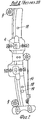
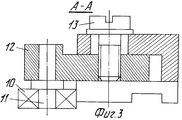
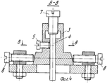
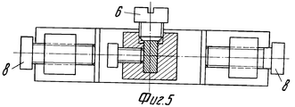
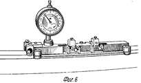
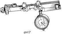
На фиг. 1 показан общий вид устройства, вид сверху и сбоку; на фиг.2 - вид снизу (со стороны опорной поверхности); на фиг.3 - сечение А-А фиг.1, на фиг. 4 - сечение Б-Б фиг.1, на фиг.5 сечение В-В фиг.В-В фиг.4; на фиг.6 - предлагаемое устройство в рабочем положении на адаптере, на фиг.7 - установка резца по индикатору. In FIG. 1 shows a general view of the device, a top view and a side view; figure 2 is a bottom view (from the supporting surface); figure 3 is a section aa of figure 1; 4 is a section BB of FIG. 1, FIG. 5 is a section BB of FIG. BB of FIG. 4; in Fig.6 - the proposed device in operating position on the adapter, Fig.7 - installation of the cutter on the indicator.
Устройство для доработки и ремонта пазов, канавок, фасок и других тому подобных элементов профиля во фланцах изделий содержит корпус 1 с базовой поверхностью 2, резцедержатели 3 крепления инструментов (резцов) 4 для обработки требуемых поверхностей. Инструмент крепится винтами 5,6 в гнезде резцедержателя. Винтами 7 резец может перемещаться (регулироваться) относительно базовой поверхности 2. Сам резцедержатель с помощью винтов 8 может выставляться в поперечном к направлению обработки направлении. Опорная (базовая) поверхность корпуса устройства выполнена в соответствии с формой обрабатываемого изделия. Корпус имеет базирующий его в радиальном направлении элементы (направляющие элементы) в виде боковых опор с возможностью их регулирования в форме подшипников 9, 10. Из них два подшипника 9 установлены на осях по концам длинной выпуклой стороны корпуса с внешней стороны, а третья опора - подшипник 10 монтирован на оси 11, закрепленной в кронштейне 12. При этом сам кронштейн 12 установлен в корпусе с внутренней, вогнутой стороны, (со стороны, противоположной двум другим подшипникам в средней его части), с возможностью его регулировки и закрепления винтом 13, который может смещаться в овальном отверстии корпуса. Тем самым есть возможность закреплять кронштейн со средним подшипником ближе или дальше от его продольной оси корпуса. Кроме того, кронштейн среднего подшипника (средней опоры) постоянно дополнительно поджимается пружиной 14 в стороны корпуса устройства, обеспечивая всегда надежный контакт опор подшипников с обрабатываемой деталью. Подшипники монтированы ниже уровня базовой поверхности. A device for finalizing and repairing grooves, grooves, chamfers and other similar profile elements in the product flanges comprises a housing 1 with a base surface 2, tool holders 3 for fastening tools (cutters) 4 for processing the required surfaces. The tool is fastened with screws 5.6 in the socket of the tool holder. Screws 7, the cutter can be moved (adjusted) relative to the base surface 2. The tool holder itself can be set with
На одном из концов корпуса монтирован хомут 15 с двумя гнездами 16 под установку в них индикатора 17. Между крайними подшипниками и ближними к ним резцедержателями выполнены сквозные отверстия (гнезда) 18,19. Гнезда 18 - под установку индикатора через кронштейны 20 для выставления резца в рабочее положение, а гнездо 19 - под установку индикатора для контроля неровностей обрабатываемой поверхности и обработки изделий. A clamp 15 with two sockets 16 is mounted at one end of the housing for mounting indicator 17. Through holes (sockets) 18,19 are made between the extreme bearings and the toolholders closest to them. Sockets 18 - for the installation of the indicator through the brackets 20 for setting the cutter in the working position, and socket 19 - for the installation of the indicator to control the unevenness of the processed surface and processing products.
Работа устройства происходит следующим образом. The operation of the device is as follows.
Устанавливается предлагаемое устройство без резца и индикатора на обрабатываемое изделие, например, шпангоут, расположив подшипники на нужных диаметрах опорных направляющих, (базовых сторонах), обрабатываемого изделия и проверяется ход устройства по изделию. Устанавливается индикатор поочередно в каждое из гнезд 16 и, перемещая устройство вдоль обрабатываемого изделия контролируется (определяется) состояние обрабатываемой поверхности или кромки перед началом обработки. Далее устанавливается индикатор на устройство через кронштейн 20 и выставляется резец в нужное положение на нужную глубину, обеспечивая подачу резца в зону резания винтом 7 и винтами 8. Установив устройство в рабочее положение, доводку обрабатываемой поверхности до необходимого размера (например, имеющегося радиуса полки шпангоута) производят путем перемещения устройства вручную (например, по полке шпангоута как по направляющей с одновременным контролем обработки индикатора, установленным в кронштейн 21. The proposed device is installed without a cutter and indicator on the workpiece, for example, a frame, placing the bearings on the desired diameters of the support rails (base sides) of the workpiece and checking the progress of the device on the product. The indicator is installed alternately in each of the sockets 16 and, moving the device along the workpiece, the state of the surface or edge to be processed is monitored (determined) before the start of processing. Next, the indicator is mounted on the device through the bracket 20 and the cutter is set to the desired position to the desired depth, ensuring the supply of the cutter to the cutting area with screw 7 and
Claims (3)
Priority Applications (1)
| Application Number | Priority Date | Filing Date | Title |
|---|---|---|---|
| RU97103104A RU2110373C1 (en) | 1997-02-28 | 1997-02-28 | Apparatus for finishing and repairing grooves, slots, chamfers and so on portions in flanges of shapes |
Applications Claiming Priority (1)
| Application Number | Priority Date | Filing Date | Title |
|---|---|---|---|
| RU97103104A RU2110373C1 (en) | 1997-02-28 | 1997-02-28 | Apparatus for finishing and repairing grooves, slots, chamfers and so on portions in flanges of shapes |
Publications (2)
| Publication Number | Publication Date |
|---|---|
| RU2110373C1 true RU2110373C1 (en) | 1998-05-10 |
| RU97103104A RU97103104A (en) | 1998-10-10 |
Family
ID=20190365
Family Applications (1)
| Application Number | Title | Priority Date | Filing Date |
|---|---|---|---|
| RU97103104A RU2110373C1 (en) | 1997-02-28 | 1997-02-28 | Apparatus for finishing and repairing grooves, slots, chamfers and so on portions in flanges of shapes |
Country Status (1)
| Country | Link |
|---|---|
| RU (1) | RU2110373C1 (en) |
Citations (2)
| Publication number | Priority date | Publication date | Assignee | Title |
|---|---|---|---|---|
| US4492011A (en) * | 1981-01-16 | 1985-01-08 | Antoine Zaragoza | Scraper to rough down the surfaces of a coated finish |
| US4583895A (en) * | 1980-01-17 | 1986-04-22 | Franz Plasser Bahnbaumaschinen-Industriegesellschaft M.B.H | Mobile machine for removing surface irregularities from a rail head of a railroad track |
-
1997
- 1997-02-28 RU RU97103104A patent/RU2110373C1/en not_active IP Right Cessation
Patent Citations (2)
| Publication number | Priority date | Publication date | Assignee | Title |
|---|---|---|---|---|
| US4583895A (en) * | 1980-01-17 | 1986-04-22 | Franz Plasser Bahnbaumaschinen-Industriegesellschaft M.B.H | Mobile machine for removing surface irregularities from a rail head of a railroad track |
| US4492011A (en) * | 1981-01-16 | 1985-01-08 | Antoine Zaragoza | Scraper to rough down the surfaces of a coated finish |
Similar Documents
| Publication | Publication Date | Title |
|---|---|---|
| RU2358850C2 (en) | Method and device to process panels | |
| JPH08215960A (en) | Machine tools for drilling and milling | |
| JPH08215961A (en) | Machine tools for drilling and milling | |
| RU96109213A (en) | RAIL GRINDING DEVICE | |
| CN100387392C (en) | machine tool | |
| CA2624817C (en) | Method and apparatus for weld profiling | |
| CN110774063A (en) | Gear hob sharpening machine with adjustable sharpening angle | |
| JPH0885011A (en) | Cutter with guide roller, cutting device and processing machine | |
| CN111922644A (en) | Groove plate machining method and cutter for machining | |
| RU2110373C1 (en) | Apparatus for finishing and repairing grooves, slots, chamfers and so on portions in flanges of shapes | |
| JPH08262181A (en) | Reactor pressure vessel flange seal face processing repair device | |
| KR20130082242A (en) | Hole drilling apparatus for work piece | |
| JP3038083B2 (en) | Nozzle changing device in laser beam machine | |
| CN113523945B (en) | Device for removing inner and outer burrs of straight welded pipe | |
| CN117464559B (en) | Machining fixture structure for double-end face grinder | |
| US6352194B1 (en) | Method and apparatus for cutting pieces from, and welding pieces into, sheet metal | |
| CN209647779U (en) | Electric discharge machine tool and production line including the same | |
| US4448340A (en) | Apparatus for replacing bolster rings | |
| CN218080592U (en) | Automatic chamfering device for turnout steel rail piece | |
| US3889575A (en) | Device for profiling the rail head of vignoles rails | |
| US4209910A (en) | Auxiliary device for vertical turning and boring machine tools | |
| CN114905092A (en) | Sawing machine for machining gear blank | |
| US4330076A (en) | Method for replacing bolster rings | |
| CN219113329U (en) | Welding fixture | |
| JP2000084848A (en) | Grinder |
Legal Events
| Date | Code | Title | Description |
|---|---|---|---|
| MM4A | The patent is invalid due to non-payment of fees |
Effective date: 20160229 |