RU2108248C1 - Automobile brake with booster - Google Patents
Automobile brake with booster Download PDFInfo
- Publication number
- RU2108248C1 RU2108248C1 RU95110940A RU95110940A RU2108248C1 RU 2108248 C1 RU2108248 C1 RU 2108248C1 RU 95110940 A RU95110940 A RU 95110940A RU 95110940 A RU95110940 A RU 95110940A RU 2108248 C1 RU2108248 C1 RU 2108248C1
- Authority
- RU
- Russia
- Prior art keywords
- cylinder
- movable
- force
- piston
- pneumatic piston
- Prior art date
Links
Images
Classifications
-
- B—PERFORMING OPERATIONS; TRANSPORTING
- B60—VEHICLES IN GENERAL
- B60T—VEHICLE BRAKE CONTROL SYSTEMS OR PARTS THEREOF; BRAKE CONTROL SYSTEMS OR PARTS THEREOF, IN GENERAL; ARRANGEMENT OF BRAKING ELEMENTS ON VEHICLES IN GENERAL; PORTABLE DEVICES FOR PREVENTING UNWANTED MOVEMENT OF VEHICLES; VEHICLE MODIFICATIONS TO FACILITATE COOLING OF BRAKES
- B60T13/00—Transmitting braking action from initiating means to ultimate brake actuator with power assistance or drive; Brake systems incorporating such transmitting means, e.g. air-pressure brake systems
- B60T13/10—Transmitting braking action from initiating means to ultimate brake actuator with power assistance or drive; Brake systems incorporating such transmitting means, e.g. air-pressure brake systems with fluid assistance, drive, or release
- B60T13/24—Transmitting braking action from initiating means to ultimate brake actuator with power assistance or drive; Brake systems incorporating such transmitting means, e.g. air-pressure brake systems with fluid assistance, drive, or release the fluid being gaseous
- B60T13/46—Vacuum systems
- B60T13/52—Vacuum systems indirect, i.e. vacuum booster units
- B60T13/573—Vacuum systems indirect, i.e. vacuum booster units characterised by reaction devices
-
- B—PERFORMING OPERATIONS; TRANSPORTING
- B60—VEHICLES IN GENERAL
- B60T—VEHICLE BRAKE CONTROL SYSTEMS OR PARTS THEREOF; BRAKE CONTROL SYSTEMS OR PARTS THEREOF, IN GENERAL; ARRANGEMENT OF BRAKING ELEMENTS ON VEHICLES IN GENERAL; PORTABLE DEVICES FOR PREVENTING UNWANTED MOVEMENT OF VEHICLES; VEHICLE MODIFICATIONS TO FACILITATE COOLING OF BRAKES
- B60T13/00—Transmitting braking action from initiating means to ultimate brake actuator with power assistance or drive; Brake systems incorporating such transmitting means, e.g. air-pressure brake systems
- B60T13/10—Transmitting braking action from initiating means to ultimate brake actuator with power assistance or drive; Brake systems incorporating such transmitting means, e.g. air-pressure brake systems with fluid assistance, drive, or release
- B60T13/24—Transmitting braking action from initiating means to ultimate brake actuator with power assistance or drive; Brake systems incorporating such transmitting means, e.g. air-pressure brake systems with fluid assistance, drive, or release the fluid being gaseous
- B60T13/46—Vacuum systems
- B60T13/52—Vacuum systems indirect, i.e. vacuum booster units
- B60T13/565—Vacuum systems indirect, i.e. vacuum booster units characterised by being associated with master cylinders, e.g. integrally formed
-
- B—PERFORMING OPERATIONS; TRANSPORTING
- B60—VEHICLES IN GENERAL
- B60T—VEHICLE BRAKE CONTROL SYSTEMS OR PARTS THEREOF; BRAKE CONTROL SYSTEMS OR PARTS THEREOF, IN GENERAL; ARRANGEMENT OF BRAKING ELEMENTS ON VEHICLES IN GENERAL; PORTABLE DEVICES FOR PREVENTING UNWANTED MOVEMENT OF VEHICLES; VEHICLE MODIFICATIONS TO FACILITATE COOLING OF BRAKES
- B60T13/00—Transmitting braking action from initiating means to ultimate brake actuator with power assistance or drive; Brake systems incorporating such transmitting means, e.g. air-pressure brake systems
- B60T13/10—Transmitting braking action from initiating means to ultimate brake actuator with power assistance or drive; Brake systems incorporating such transmitting means, e.g. air-pressure brake systems with fluid assistance, drive, or release
- B60T13/24—Transmitting braking action from initiating means to ultimate brake actuator with power assistance or drive; Brake systems incorporating such transmitting means, e.g. air-pressure brake systems with fluid assistance, drive, or release the fluid being gaseous
- B60T13/46—Vacuum systems
- B60T13/52—Vacuum systems indirect, i.e. vacuum booster units
- B60T13/569—Vacuum systems indirect, i.e. vacuum booster units characterised by piston details, e.g. construction, mounting of diaphragm
Abstract
Description
Изобретение относится к тормозному устройству с усилителем, которое предназначено для автомобиля и включает в себя, в одной стороны, главный цилиндр, заполненный тормозной жидкостью и снабженный главным гидравлическим поршнем для восприятия воздействующего усилия, состоящего из подводимого усилия и добавочного усилия, действующих оба в осевом направлении, и, с другой стороны, пневматический усилитель, способный приводиться в действие путем приложения указанного подводимого усилия к тяге управления для открывания клапана, чтобы создавать указанное воздействующее усилие на главный гидравлический поршень. Усилитель включает в себя жесткий корпус, герметически разделенный на две камеры по крайней мере одной подвижной перегородкой, способной подвергаться напряжению под действием перепада давлений между двумя камерами, возникающего при открывании клапана, и приводить в движение пневматический поршень, который может двигаться относительно корпуса, несет на себе указанный клапан и способствует, по крайней мере, передаче указанного добавочного усилия. Сам главный гидравлический поршень главного цилиндра представляет собой полый подвижный цилиндр, который сообщается с главным цилиндром, воспринимает по крайней мере часть добавочного усилия и внутри которого герметичным образом в осевом направлении перемещается вспомогательный гидравлический поршень, способный воспринимать по крайней мере, указанное подводимое усилие. The invention relates to a brake device with an amplifier, which is intended for a car and includes, on the one hand, a master cylinder filled with brake fluid and equipped with a main hydraulic piston for receiving an acting force consisting of an applied force and an additional force acting both in the axial direction and, on the other hand, a pneumatic amplifier capable of being driven by applying said applied force to the control rod to open the valve to create amb said acting force on the main hydraulic piston. The amplifier includes a rigid housing, hermetically divided into two chambers by at least one movable partition, capable of undergoing stress under the action of the pressure differential between the two chambers that occurs when the valve is opened, and actuating a pneumatic piston that can move relative to the housing carries the specified valve and contributes, at least, to the transmission of the indicated additional force. The main hydraulic piston of the main cylinder itself is a hollow movable cylinder that communicates with the main cylinder, receives at least part of the additional force, and inside which the auxiliary hydraulic piston is able to absorb at least the specified applied force in the axial direction.
Устройство этого типа хорошо известно в технике и описано, например, в патенте США N 4491058 или в документе FR-A-2558126. A device of this type is well known in the art and is described, for example, in US Pat. No. 4,491,058 or in FR-A-2558126.
Такое тормозное устройство имеет преимущество, проистекающее из использования пневматического поршня, который может двигаться по отношению к жесткому корпусу, при этом общая длина хода, доступная для тяги управления и, следовательно, для педали тормоза, сравнительно большая, что представляет собой условие, необходимое для обеспечения оптимального управления замедлением транспортного средства при торможении. Such a braking device has the advantage resulting from the use of a pneumatic piston, which can move relative to the rigid body, while the total stroke length available for the control rod and, therefore, for the brake pedal is relatively large, which is a condition necessary to ensure optimal control of vehicle deceleration during braking.
Однако это условие, хотя и необходимое, является недостаточным, в современных тормозных устройствах с усилителем это управление ослаблено из-за того, что для достижения минимального давления, необходимого для начала торможения, требуется очень большая первоначальная длина хода тяги управления. However, this condition, although necessary, is insufficient; in modern brake devices with an amplifier, this control is weakened because in order to achieve the minimum pressure required to start braking, a very large initial stroke length of the control rod is required.
Целью настоящего изобретения является оптимизация управления водителем транспортного средства замедлением последнего путем предложенного усилителем тормозного устройства с гидравлическим противодействием, способного создавать силу торможения, которая увеличивается намного более равномерно как функция длины хода тяги управления и, следовательно, педали тормоза, чем в современных устройствах. The aim of the present invention is to optimize the control of a vehicle driver by slowing down the latter by means of a hydraulic braking device proposed by the booster capable of generating braking force that increases much more uniformly as a function of the stroke length of the control rod and, therefore, the brake pedal than in modern devices.
В конечном счете, устройство по настоящему изобретению по существу отличается тем, что подвижная перегородка скользяще установлена на пневматическом поршне с тем, чтобы быть способной передвигаться относительно него в направлении к главному цилиндру от первоначального относительного положения, в котором она упирается в пневматический поршень в направлении, противоположном тому, которое указывает к главному цилиндру, и что эта подвижная перегородка, когда она находится в напряженном состоянии под действием перепада давлений, давит по крайней мере косвенно на подвижный цилиндр в направлении к главному цилиндру. Ultimately, the device of the present invention is essentially characterized in that the movable baffle is slidably mounted on the pneumatic piston so as to be able to move relative to it towards the main cylinder from the initial relative position in which it abuts the pneumatic piston in the direction opposite to that which points to the main cylinder, and that this movable partition, when it is in a stressed state under the action of a pressure differential, presses at least indirectly onto the movable cylinder towards the master cylinder.
Согласно предпочтительному варианту осуществления изобретения между пневматическим поршнем и подвижной перегородкой расположено упругое средство, чтобы создавать силу упругости, противоположную свободному относительному передвижению этой подвижной перегородки и этого пневматического поршня, причем этим упругим средством, например, является спиральная пружина. According to a preferred embodiment of the invention, elastic means are arranged between the pneumatic piston and the movable baffle to create an elastic force opposite to the free relative movement of this movable baffle and this pneumatic piston, this elastic means, for example, being a coil spring.
Другие особенности и преимущества изобретения будут ясны из описания, которое приводится ниже с целью указания и без какого-либо ограничения со ссылкой на прилагаемые чертежи. Other features and advantages of the invention will be apparent from the description that is given below for the purpose of indicating and without any limitation with reference to the accompanying drawings.
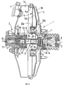
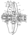
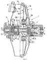
На фиг. 1 изображен вид при частичном разрезе устройства согласно настоящему изобретению; на фиг. 2 и 3 - виды при частичном разрезе устройства согласно одному варианту настоящего изобретения, показанного в различных стадиях работы; на фиг. 4 - вид при частичном разрезе устройства согласно другому варианту настоящего изобретения. In FIG. 1 is a partial sectional view of a device according to the present invention; in FIG. 2 and 3 are partial sectional views of a device according to one embodiment of the present invention, shown in various stages of operation; in FIG. 4 is a partial sectional view of a device according to another embodiment of the present invention.
Поскольку изобретение относится только к усовершенствованию, сделанному в тормозных системах с пневматическим усилием, и общая конструкция и работа последних хорошо известна специалисту, то эти системы здесь будут упоминаться только вскользь, чтобы дать общее представление об усовершенствовании, которое представляет собой изобретение. Since the invention relates only to the improvement made in brake systems with pneumatic force, and the general design and operation of the latter is well known to the specialist, these systems will be mentioned here only in passing to give an overview of the improvement that the invention represents.
Схематически устройство этого типа состоит из усилителя 1 и главного цилиндра 2. Schematically, a device of this type consists of an
Сам усилитель имеет жесткий корпус 3, герметично разделенный на две камеры 3a и 3b подвижной перегородки 4, состоящей из диафрагмы 4a и жесткой юбки 4b и способной двигать пневматический поршень 5, который может перемещаться внутри корпуса 3. The amplifier itself has a
Передняя камера 3a, которая с передней стороны герметично закрыта главным цилиндром 2, постоянно соединена с источником разрежения (не показан) через обратный клапан 6. Давление в задней камере 3b регулируется трехходовым клапаном 7, контролируемым тягой управления 8, которая соединена с педалью тормоза (не показана). The
Когда тяга управления 8 находится в положении покоя, т.е. в этом случае втянутой вправо, клапан 7 устанавливает сообщение между двумя карманами 3a и 3b усилителя или выходит из положения, в котором это сообщение установлено. When the
Поскольку задняя камера 3b находится, таким образом, при таком же разрежении, как и передняя камера 3a, то поршень 5 пружиной 9 отодвинут вправо в положение покоя. Since the
Перемещение тяги управления 8 влево имеет результатом, в первую очередь, движение клапана 7 с тем, чтобы он изолировал камеры 3a и 3b одну от другой, и затем, во вторую очередь, движение этого клапана с тем, чтобы он открыл заднюю камеру 3b для сообщения с атмосферой. Moving the
Перепад давлений между двумя камерами, воспринимаемый, следовательно, диафрагмой 4a, вызывает действие осевого давления на подвижную перегородку 4, которое стремится перемещать ее влево и позволяет ей двигать поршень 5, который, в свою очередь, перемещается, сжимая таким образом пружину 9. The pressure difference between the two chambers, which is therefore perceived by the diaphragm 4a, causes axial pressure on the
Следовательно, усилие торможения приложенное к тяге управления 8, или "подводимое усилие" и добавочное усилие тормоза или "добавочное усилие", вызываемое давлением на подвижную перегородку 4, прилагаются вместе вдоль оси 10 толкателя 21 в направлении к главному цилиндру 2 и объединяются для образования усилия, воздействующего на последний. Therefore, the braking force applied to the
Точнее, воздействующего усилие прилагается к главному гидравлическому поршню 11 главного цилиндра и вызывает его движение влево (фиг. 1), которое приводит к увеличению давления тормозной жидкости, находящейся во внутреннем объеме 12 главного цилиндра, и срабатывание тормоза, соединенного с последним. More precisely, the acting force is applied to the main
Главный гидравлический поршень 11 в действительности является и содержит, с одной стороны, подвижный и полый цилиндр 13 и, с другой стороны, вспомогательный гидравлический поршень 14. The main
Внутренний объем 15 подвижного цилиндра 13 сообщается с внутренним объемом 12 главного цилиндра через отверстия, например, 16 и 17, сделанные в подвижном цилиндре в осевом направлении. Не говоря уже о прохождении жидкости через отверстия 16 и 17 между внутренним объемом 12 главного цилиндра 2 и внутренним объемом подвижного цилиндра 13, этот подвижный цилиндр 13 может при сохранении герметичности передвигаться в главный цилиндр 3, при этом герметичность достигается посредством по крайней мере кольцевого уплотнения 18. The
Вспомогательный гидравлический поршень 14, в свою очередь, передвигается внутри подвижного цилиндра 13, в котором он герметически изолирован посредством кольцевого уплотнения 19. The auxiliary
Подвижный цилиндр 13 посредством кольца 20 соединен с жесткой юбкой 4b, с тем чтобы воспринимать по крайней мере часть добавочного усилия, прилагаемого этой юбкой. The
Вспомогательный гидравлический поршень 14 расположен вдоль оси и обращен к толкателю 21, способному передавать ему по крайней мере подводимое усилие, прилагаемое к тяге управления 8. The auxiliary
Описанное до сих пор устройство действует следующим образом. The device described so far operates as follows.
Когда к тяге управления 8 прилагается подводимое усилие, то после заранее заданного хода этой тяги управления 8 клапан 7 открывает заднюю камеру 3b усилителя, заранее изолированную от передней камеры 3b, для ее соединения с атмосферой, и жесткой юбкой 4b через кольцо 20 прилагается добавочное усилие к подвижному цилиндру 13. When an applied force is applied to the
Такой заранее заданный ход тяги управления 8 возможен благодаря определенному зазору между передним концом толкателя 21 и задний концом вспомогательного гидравлического поршня, постоянно смещенного к главному цилиндру пружиной, расположенной между заплечиком кольца 20 и заплечиком вспомогательного гидравлического поршня 14. Such a predetermined stroke of the
Гидравлическое давление во внутреннем объеме 12 главного цилиндра повышается и становится установившимся благодаря потоку гидравлической жидкости через отверстия 16 и 17 во внутренний объем 15 подвижного цилиндра, что таким образом вызывает появление противодействующей силы на вспомогательный гидравлический поршень 14, зависящий от добавочного усилия, противоположной подводимому усилию и, следовательно, позволяющей регулировать первое усилие посредством второго. The hydraulic pressure in the
Согласно изобретению подвижная перегородка 4 с помощью, предпочтительно, ее жесткой юбки 4b скользяще установлена на пневматическом поршне 5 и может передвигаться по отношению к нему в направлении к главному цилиндру 2 из положения покоя, соответствующего положению покоя усилителя, представленного на фиг. 1, в котором юбка 4b упирается в пневматический поршень 5 под действием пружин возврата главного цилиндра 2 в направлении, противоположном тому, которое указывает на главный цилиндр 2. According to the invention, the
С другой стороны, юбка 4b и пневматический поршень 5 имеют соответствующие упоры 22a и 22b, обращенные один к другому, которые позволяют юбке 4b приводить в движение пневматический поршень 5 только после определенного хода и которые, возможно, позволяют вставлять спиральную пружину 23 или любое другое средство для предотвращения свободного скольжения этой юбки по этому пневматическому поршню по всей длине перемещения, возможного между этими деталями, и резкого приведения в движение одной другого. On the other hand, the
Благодаря этим особенностям изобретенное тормозное устройство позволяет достигнуть внутри главного цилиндра 2 сравнительно высокого давления по сравнению с теми, которые обычно достигаются в известных устройствах при любой малой длине хода тяги управления 8. Owing to these features, the invented braking device makes it possible to achieve a relatively high pressure inside the master cylinder 2 compared to those that are usually achieved in known devices for any short stroke of the
Этот результат можно объяснить следующим образом. This result can be explained as follows.
Добавочное усилие, развиваемое усилителем, зависит от перепада давлений между камерами 3a и 3b, причем последний сам зависит от отверстия клапана 7. The additional force developed by the amplifier depends on the pressure difference between the
Отверстие этого клапана зависит от относительного движения между тягой управления 8 и пневматическим поршнем 5, который сам также является подвижным и несет на себе клапан 7. The hole of this valve depends on the relative movement between the
Допуская в начале работы усилителя движение подвижной перегородки 4 вперед к главному цилиндру 2 и, следовательно, увеличение внутреннего давления в последнем без полного и немедленного приведения в движение пневматического поршня 5, изобретение делает возможным относительное движение тяги управления 8 по отношению к этому поршню для приближения к абсолютному движению этой тяги (8), соотнесенному к фиксированной точке в пространстве, с которой при одинаковой длине хода тяги управления 8 начинается появление более высокого давления в главном цилиндре 2. Assuming at the beginning of the operation of the amplifier the movement of the
Когда упоры 22a и 22b соприкоснутся друг с другом, то при дальнейшей работе усилителя не происходит больше никакого относительного движения между юбкой 4b и поршнем 5, которые затем движутся вместе, как и в обычном усилителе, при этом поддерживается перепад давлений в главном цилиндре 2, соответствующий известной технике. When the
Как можно затем видеть, изобретение предоставляет тормозное устройство с усилителем, в котором часть хода юбки 4b и главного гидравлического поршня 11 главного цилиндра является скрытой по отношению к ходу тяги управления 8, чтио при работе дает более высокое давление в главном цилиндре. As you can then see, the invention provides a brake device with an amplifier, in which part of the stroke of the
Другое важное преимущество, предоставляемое изобретением, заключается в том, что кольцо 20, расположенное между жесткой юбкой 4b и подвижным цилиндром 13, позволяет путем его регулировки, например, завинчиванием или вывинчиванием изменять расстояние в покое между передним концом толкателя 21 и задним концом вспомогательного гидравлического поршня 13 и таким образом регулировать величину резкого изменения в работе усилителя, которая является важным параметром его работы. Another important advantage provided by the invention is that the
На фиг. 2 и 3 показаны два рабочих положения усилителя согласно вышеописанному варианту осуществления изобретения. На этих рисунках детали, идентичные или аналогичные тем, которые показаны на фиг. 1, имеют одинаковые числовые обозначения. In FIG. 2 and 3 show two operating positions of an amplifier according to the above-described embodiment of the invention. In these figures, parts identical or similar to those shown in FIG. 1 have the same numerical designations.
Согласно этому варианту вспомогательный гидравлический поршень 14 имеет удлинение в осевом направлении в виде штока 21, способного передавать ему, с одной стороны, подводимое усилие, прилагаемое к тяге управления 8, и, с другой стороны, часть добавочного усилия, создаваемого пневматическим поршнем 5, причем эти силы передаются способом, известным по существу посредством опорного диска 26, с одной стороны которого примыкают этот пневматический поршень и прокладка 24, на которую воздействует тяга управления, а с другой стороны - чашка 25, которая прочно прикреплена к штоку 21. According to this embodiment, the auxiliary
Работа этого усилителя полностью сходна с работой усилителя на фиг. 1. Когда к тяге управления 8 приложено подводимое усилие, то после заранее заданной длины хода тяги управления 8 клапан 7 открывает заднюю камеру 3b усилителя, заранее изолированную от передней камеры 3a, для ее соединения с атмосферой, и добавочное усилие прикладывается к подвижному цилиндру 13 посредством жесткой юбки 4b через кольцо 20. The operation of this amplifier is completely similar to the operation of the amplifier in FIG. 1. When an applied force is applied to the
Гидравлическое давление во внутреннем объеме 12 главного цилиндра явно повышается и становится установившимся благодаря потоку гидравлической жидкости через каналы 16 и 17 во внутренний объем 15 подвижного цилиндра, что таким образом, вызывает появление противодействующей силы на вспомогательный гидравлический поршень 14, зависящий от добавочного усилия, противоположной усилию, передаваемому через опорный диск 23, и позволяющей регулировать добавочное усилие подводимым усилием посредством комбинированного противодействия, т.е. одновременно гидравлического и механического. The hydraulic pressure in the
Как описано ранее, подвижная перегородка 4 с помощью предпочтительно ее жесткой юбки 4b скользяще установлена на пневматическом поршне 4 и может передвигаться по отношению к нему в направлении к главному цилиндру 2. As previously described, the
Точнее, относительное передвижение происходит из положения покоя, которое соответствует положению покоя усилителя, как это представлено на фиг. 2, и в котором юбка 4b упирается в пневматический поршень 5 (в данном случае через кольцо 20) под действием пружин возврата главного цилиндра 2 в направлении, противоположном тому, которое указывает на главный цилиндр 2, в положение, представленное на фиг. 3, в котором юбка 4b двигает пневматический поршень 5 к главному цилиндру. More precisely, the relative movement comes from the resting position, which corresponds to the resting position of the amplifier, as shown in FIG. 2, and in which the
Соответствующие упоры 22a, 22b, обращенные друг к другу, гарантируют, что юбка 4b будет двигать пневматический поршень 5 только заранее заданной относительной длины хода, соответствующей расстоянию, которое разделяет эти упоры в положении покоя. The
Этот вариант осуществления изобретения также делает возможным достижение внутри главного цилиндра 2 сравнительно высокого давления по отношению к тем, которые обычно достигаются в известных устройствах, при любой малой длине хода тяги управления 8 и использовании опорного диска. This embodiment of the invention also makes it possible to achieve a relatively high pressure inside the master cylinder 2 with respect to those that are usually achieved in known devices, for any small stroke length of the
На фиг. 4 показан другой вариант осуществления изобретения, который может быть использован в усилителе, описанном на фиг. 1, а также в усилителе, описанном на фиг. 2 и 3. In FIG. 4 shows another embodiment of the invention that can be used in the amplifier described in FIG. 1, as well as in the amplifier described in FIG. 2 and 3.
Действительно, при включении в действие тормозного устройства было показано, что после первой рабочей стадии сборка из жесткой юбки 4b и пневматического поршня 5 целиком движется влево (при рассмотрении чертежей) в относительное положение, показанное на фиг. 3, при этом прогрессивно увеличивается давление в задней камере 3b. Indeed, when the braking device was activated, it was shown that after the first working stage, the assembly of the
Когда это давление сравняется с атмосферным давлением, усилитель действует в так называемой фазе насыщения и добавочное усилие больше не увеличивается и остается постоянным, в то время как подводимое усилие можно по-прежнему увеличивать водителем транспортного средства. When this pressure is equal to atmospheric pressure, the amplifier operates in the so-called saturation phase and the additional force no longer increases and remains constant, while the applied force can still be increased by the driver of the vehicle.
Следовательно, в начале этой стадии насыщения равновесие сил показывает, что любое увеличение подводимого усилия на тягу управления 8 приводит только к движению вперед пневматического поршня 5 и движению назад жесткой юбки 4b до тех пор, пока они не войдут во взаимное соприкосновение, с тем чтобы пневматический поршень 5 двигал юбку 4b к главному цилиндру. Therefore, at the beginning of this saturation stage, the balance of forces shows that any increase in the applied force to the
При перемещении поршня 5 и, следовательно, тяги управления 8 и соединенной с ней педали тормоза не происходит никакого увеличения давления во внутреннем объеме 12 главного цилиндра. Это явление может неприятно ощущаться водителем, и вариант, показанный на фиг. 4, устраняет это явление. When moving the
Как можно видеть на фиг. 4, внутренний объем 15 подвижного цилиндра 13 сообщается с внутренним объемом 12 главного цилиндра 2 по крайней мере через одно отверстие для замедления потока жидкости, как, например, ограничитель объемной скорости потока, расположенный в отверстии 16, и по крайней мере через один обратный клапан, например, расположенный в отверстии 17, который допускает только поток тормозной жидкости из главного цилиндра в подвижный цилиндр. As can be seen in FIG. 4, the
Таким образом, сборка из ограничителя и обратного клапана представляет собой селективный понизитель объемной скорости потока, который не оказывает сколько-нибудь заметного влияния на работу усилителя до стадии насыщения, но который допускает в начале последней движение вперед подвижного цилиндра 13, когда пневматический поршень движется вперед, и таким образом, достижение непрерывного увеличения давления в главном цилиндре, когда водитель транспортного средства продолжает нажимать на педаль тормоза. Thus, the assembly of the restrictor and non-return valve is a selective volumetric flow rate reducer that does not have any noticeable effect on the operation of the amplifier until the saturation stage, but which allows the
Claims (4)
Applications Claiming Priority (5)
| Application Number | Priority Date | Filing Date | Title |
|---|---|---|---|
| FR9211623A FR2696141B1 (en) | 1992-09-30 | 1992-09-30 | Assisted braking system with hydraulic reaction and concealed stroke. |
| FR9211623 | 1992-09-30 | ||
| FR9300571A FR2700513B1 (en) | 1993-01-21 | 1993-01-21 | Assisted braking system with mixed reaction and concealed stroke. |
| FR9300571 | 1993-01-21 | ||
| PCT/FR1993/000917 WO1994007723A1 (en) | 1992-09-30 | 1993-09-22 | Power braking system with a shortened stroke |
Publications (2)
| Publication Number | Publication Date |
|---|---|
| RU95110940A RU95110940A (en) | 1997-02-10 |
| RU2108248C1 true RU2108248C1 (en) | 1998-04-10 |
Family
ID=26229760
Family Applications (1)
| Application Number | Title | Priority Date | Filing Date |
|---|---|---|---|
| RU95110940A RU2108248C1 (en) | 1992-09-30 | 1993-09-22 | Automobile brake with booster |
Country Status (15)
| Country | Link |
|---|---|
| US (1) | US5475978A (en) |
| EP (1) | EP0662895B1 (en) |
| JP (1) | JP3393257B2 (en) |
| KR (1) | KR100298465B1 (en) |
| CN (1) | CN1035867C (en) |
| AU (1) | AU671297B2 (en) |
| BR (1) | BR9307074A (en) |
| CZ (1) | CZ79395A3 (en) |
| DE (1) | DE69301612T2 (en) |
| ES (1) | ES2085797T3 (en) |
| PL (1) | PL172201B1 (en) |
| RU (1) | RU2108248C1 (en) |
| TR (1) | TR28122A (en) |
| TW (1) | TW241233B (en) |
| WO (1) | WO1994007723A1 (en) |
Families Citing this family (13)
| Publication number | Priority date | Publication date | Assignee | Title |
|---|---|---|---|---|
| FR2724354A1 (en) * | 1994-09-08 | 1996-03-15 | Alliedsignal Europ Services | ASSISTED BRAKING DEVICE WITH MASKED TRAVEL AND INCREASED SAFETY |
| FR2729354B1 (en) * | 1995-01-18 | 1997-05-16 | Alliedsignal Europ Services | ASSISTED BRAKING DEVICE WITH REDUCED TRAVEL |
| JP3528991B2 (en) * | 1995-05-29 | 2004-05-24 | 株式会社ボッシュオートモーティブシステム | Brake booster |
| US5802852A (en) * | 1997-06-20 | 1998-09-08 | Robert Bosch Technology Corporation | Brake booster with an integrated master cylinder |
| DE19802846A1 (en) * | 1998-01-26 | 1999-08-05 | Lucas Ind Plc | Manually and automatically operated braking force amplifier or main cylinder unit with defined manual actuator element rest position |
| US7279198B1 (en) * | 2001-10-16 | 2007-10-09 | Thilmany Llc | Method for extrusion coating a lightweight web |
| FR2860472B1 (en) * | 2003-10-06 | 2006-01-20 | Bosch Gmbh Robert | PNEUMATIC BRAKE ASSIST SERVOMOTOR COMPRISING A SERRATED DIAPHRAGM |
| FR2897820B1 (en) * | 2006-02-27 | 2009-01-16 | Bosch Gmbh Robert | SERVOFREIN AND MOUNTING METHOD |
| FR2940948B1 (en) * | 2009-01-15 | 2010-12-31 | Bosch Gmbh Robert | RESTRAINING GAME SIMULATOR FOR VEHICLE BOOSTER |
| CN103496364B (en) * | 2013-09-03 | 2016-03-30 | 广东中博汽车零部件有限公司 | Pre-brake type vacuum booster and having brake master cylinder assembly thereof |
| CN105799678B (en) * | 2014-12-30 | 2019-05-28 | 罗伯特·博世有限公司 | The brake booster and motor vehicle braking system of hydraulic braking power-assisted are provided |
| JP6428661B2 (en) * | 2016-01-25 | 2018-11-28 | 株式会社アドヴィックス | Negative pressure booster |
| CN108501919A (en) * | 2018-05-09 | 2018-09-07 | 广东中博汽车零部件有限公司 | A kind of vacuum booster of adjustable idle stroke |
Family Cites Families (13)
| Publication number | Priority date | Publication date | Assignee | Title |
|---|---|---|---|---|
| US3222868A (en) * | 1963-02-08 | 1965-12-14 | Kelsey Hayes Co | Brake operating mechanism |
| US3293849A (en) * | 1963-10-11 | 1966-12-27 | Chrysler Corp | Vehicle braking system |
| US3350882A (en) * | 1964-10-06 | 1967-11-07 | Chrysler Corp | Vehicle braking system |
| BE676228A (en) * | 1965-07-23 | 1966-06-16 | ||
| US3470695A (en) * | 1967-09-18 | 1969-10-07 | Teves Gmbh Alfred | Vacuum-assist power brake |
| US3613506A (en) * | 1969-07-17 | 1971-10-19 | Bendix Corp | Servomotor having improved no-power operation |
| US4110985A (en) * | 1976-04-09 | 1978-09-05 | General Motors Corporation | Dual power brake booster |
| AU507295B2 (en) * | 1976-05-19 | 1980-02-07 | Automotive Products Limited | Servo-assisted hydraulic master cylinder |
| FR2532084A1 (en) * | 1982-08-20 | 1984-02-24 | Dba | STOP KEY FOR ASSISTANCE SERVOMOTOR VALVE DIVER AND ASSISTANCE SERVOMOTOR EQUIPPED WITH SUCH KEY |
| JPS5992243A (en) * | 1982-11-17 | 1984-05-28 | Jidosha Kiki Co Ltd | Booster for braking force |
| DE3401402C2 (en) * | 1984-01-17 | 1993-09-30 | Teves Gmbh Alfred | Vacuum brake booster |
| DE8622758U1 (en) * | 1986-08-25 | 1987-12-23 | Lucas Industries P.L.C., Birmingham, West Midlands, Gb | |
| DE8805017U1 (en) * | 1988-04-15 | 1989-08-10 | Lucas Industries P.L.C., Birmingham, West Midlands, Gb |
-
1993
- 1993-09-03 TW TW082107194A patent/TW241233B/zh not_active IP Right Cessation
- 1993-09-22 CZ CZ95793A patent/CZ79395A3/en unknown
- 1993-09-22 BR BR9307074A patent/BR9307074A/en not_active Application Discontinuation
- 1993-09-22 RU RU95110940A patent/RU2108248C1/en active
- 1993-09-22 WO PCT/FR1993/000917 patent/WO1994007723A1/en not_active Application Discontinuation
- 1993-09-22 JP JP50876494A patent/JP3393257B2/en not_active Expired - Lifetime
- 1993-09-22 ES ES93920913T patent/ES2085797T3/en not_active Expired - Lifetime
- 1993-09-22 EP EP93920913A patent/EP0662895B1/en not_active Expired - Lifetime
- 1993-09-22 AU AU48237/93A patent/AU671297B2/en not_active Expired
- 1993-09-22 DE DE69301612T patent/DE69301612T2/en not_active Expired - Lifetime
- 1993-09-22 PL PL93308220A patent/PL172201B1/en unknown
- 1993-09-22 KR KR1019950701227A patent/KR100298465B1/en not_active IP Right Cessation
- 1993-09-27 TR TR00861/93A patent/TR28122A/en unknown
- 1993-09-28 CN CN93118206A patent/CN1035867C/en not_active Expired - Lifetime
- 1993-09-30 US US08/122,553 patent/US5475978A/en not_active Expired - Lifetime
Also Published As
| Publication number | Publication date |
|---|---|
| ES2085797T3 (en) | 1996-06-01 |
| DE69301612D1 (en) | 1996-03-28 |
| TR28122A (en) | 1996-01-16 |
| RU95110940A (en) | 1997-02-10 |
| EP0662895A1 (en) | 1995-07-19 |
| KR950703460A (en) | 1995-09-20 |
| BR9307074A (en) | 1999-08-24 |
| KR100298465B1 (en) | 2001-10-24 |
| JPH08501751A (en) | 1996-02-27 |
| DE69301612T2 (en) | 1996-07-04 |
| PL172201B1 (en) | 1997-08-29 |
| JP3393257B2 (en) | 2003-04-07 |
| CN1035867C (en) | 1997-09-17 |
| US5475978A (en) | 1995-12-19 |
| CN1088530A (en) | 1994-06-29 |
| EP0662895B1 (en) | 1996-02-21 |
| AU671297B2 (en) | 1996-08-22 |
| TW241233B (en) | 1995-02-21 |
| PL308220A1 (en) | 1995-07-24 |
| AU4823793A (en) | 1994-04-26 |
| WO1994007723A1 (en) | 1994-04-14 |
| CZ79395A3 (en) | 1995-11-15 |
Similar Documents
| Publication | Publication Date | Title |
|---|---|---|
| RU2108248C1 (en) | Automobile brake with booster | |
| US5475977A (en) | Brake-booster device with slowed hydraulic reaction | |
| US5921084A (en) | Power-assisted braking device with a variable assistance ratio | |
| US6014862A (en) | Emulator damping mechanism | |
| JP3940960B2 (en) | Boost brake system with reduced hysteresis and variable boost ratio | |
| JP3823257B2 (en) | Boost brake system with hidden process and increased safety | |
| US5487271A (en) | Brake-booster with hydraulic reaction and adjustable kick | |
| JP4207170B2 (en) | Improved master cylinder with dynamically releasable fluid reaction force | |
| USRE27784E (en) | Master cylindhi) kok hydraulic: xhak inc, sy.stkm | |
| JP4061603B2 (en) | Boost type brake device with improved safety and fluid reaction force | |
| JP3774870B2 (en) | Pneumatic brake booster | |
| JP4022692B2 (en) | Booster device with simplified compensation volume | |
| RU2155686C2 (en) | Servo-operated brake with reduced working stroke | |
| JP2002527293A (en) | Master cylinder with fluid reaction force and increased input | |
| US6904753B2 (en) | Servobrake comprising a reduced-reaction master cylinder | |
| RU2217334C2 (en) | Master cylinder with dynamic reaction adjustable by cross-section difference | |
| US5572870A (en) | Boosted brake device with concealed travel and guaranteed gain | |
| JP4131423B2 (en) | Boost brake system with improved fluid reaction force | |
| US5782159A (en) | Pneumatic booster with inertial valve | |
| JP2004515415A (en) | Boost brake device with emergency valve with high jump and booster for this device | |
| US6195993B1 (en) | Master cylinder with hydraulic reaction and selective self-powering | |
| KR20030055328A (en) | Brake booster device for motor vehicle | |
| RU2273571C2 (en) | Car brake with booster with improved operating characteristics | |
| US20020084690A1 (en) | Brake pedal feel emulator and method | |
| JP2002522290A (en) | Master cylinder with fluid reaction force that changes with pressure |