RU2105373C1 - Vacuum arc-control chamber contact - Google Patents
Vacuum arc-control chamber contact Download PDFInfo
- Publication number
- RU2105373C1 RU2105373C1 RU94010714A RU94010714A RU2105373C1 RU 2105373 C1 RU2105373 C1 RU 2105373C1 RU 94010714 A RU94010714 A RU 94010714A RU 94010714 A RU94010714 A RU 94010714A RU 2105373 C1 RU2105373 C1 RU 2105373C1
- Authority
- RU
- Russia
- Prior art keywords
- contact
- arc
- section
- resistant
- copper
- Prior art date
Links
Images

Landscapes
- Contacts (AREA)
Abstract
Description
Изобретение относится к области электротехники, в частности к контактам для вакуумных дугогасительных камер. The invention relates to the field of electrical engineering, in particular to contacts for vacuum interrupter chambers.
Известен контакт для вакуумной дугогасительной камеры, содержащий контакт - деталь с нанесенным плазменно порошковым напылением покрытия из дугостойкого материала с последующим уплотнением покрытия ионной полировкой (авт.св. СССР N 1394258, H 01 H 33/66, 1986 г.). A contact is known for a vacuum interrupter chamber containing a contact — a part with a plasma-powder spray coating of an arc-resistant material, followed by compaction of the coating by ion polishing (ed. St. USSR N 1394258, H 01 H 33/66, 1986).
Недостатками известного контакта являются низкая плотность покрытия и, как следствие, невысокая отключающая способность, в связи с чем он используется в слаботочных электрических цепях. The disadvantages of this contact are the low density of the coating and, as a consequence, the low breaking capacity, in connection with which it is used in low-current electrical circuits.
Наиболее близким по технической сущности и достигаемому результату к изобретению является контакт для вакуумной дугогасительной камеры, выполненный из одного материала в форме ветрового колеса, содержащего круглый центральный плоский участок, который окружен выполненным с ним заодно конусообразным участком с дугообразными пазами (патент США N 4324960, 13.04.82 г. ). The closest in technical essence and the achieved result to the invention is a contact for a vacuum interrupter chamber made of one material in the form of a wind wheel containing a circular central flat section, which is surrounded by a conical section made with it with arcuate grooves (US patent N 4324960, 13.04 .82 g.).
Недостатками известного устройства, принятого за прототип, являются низкая стабильность гашения дуги в режиме короткого замыкания на токах 25-35 кА, а также большой расход дорогостоящего дугостойкого материала. The disadvantages of the known device adopted for the prototype are the low stability of arc extinction in the short circuit mode at currents of 25-35 kA, as well as the high consumption of expensive arc-resistant material.
Целью настоящего изобретения является повышение отключающей способности в режиме короткого замыкания, а также уменьшение нормы расхода дорогостоящего дугогасительного контактного материала. The aim of the present invention is to increase the breaking capacity in the short circuit mode, as well as reducing the consumption rate of expensive interrupter contact material.
Указанная цель обеспечивается тем, что в качестве основной массы контакта используется медь - материал с высокой теплоемкостью, электро- и теплопроводностью, а для обеспечения дугостойкости контакт имеет жестко соединенную с ним фигурную накладку из дугостойкого материала, толщина которой в 1,2-3 раза превышает величину износа контактов, а по конфигурации повторяет поверхность контакта. This goal is ensured by the fact that the main mass of the contact is copper - a material with high heat capacity, electrical and thermal conductivity, and to ensure arc resistance, the contact has a rigidly shaped figured cover made of arc-resistant material, the thickness of which is 1.2-3 times greater the amount of wear of the contacts, and by configuration repeats the contact surface.
В процессе коммутации медный контакт обеспечивает отбор тепла от дугостойкой накладки, а так как толщина накладки небольшая, уменьшается и суммарное сопротивление контакта. Технология изготовления контакта дополнительно уплотняет дугостойкий материал. Исходя из этого создаются благоприятные условия для повышения стабильности гашения дуги, а также экономится дугостойкий материал. During the switching process, the copper contact provides heat removal from the arc-resistant lining, and since the lining thickness is small, the total contact resistance also decreases. Contact manufacturing technology further compacts the arc-resistant material. On this basis, favorable conditions are created to increase the stability of arc extinction, and also arc-resistant material is saved.
Экспериментально установлено, что наибольший эффект достигается при минимальной толщине накладки, практически толщина накладки должна находиться в пределах 1,2-3 величин износа. It was experimentally established that the greatest effect is achieved with a minimum thickness of the lining, practically the thickness of the lining should be in the range of 1.2-3 wear values.
Сопоставительный анализ с прототипом показывает, что заявленный контакт отличается тем, что состоит из контактной и дугогасительной части, изготовленной в виде накладки из дугостойкого материала и медного основания контакта, жестко соединенных между собой. Причем толщина дугостойкой накладки в 1,2-3 раза превышает величину износа контактов, а по конфигурации повторяет поверхности контакта. В известных источниках информации не обнаружено технических решений контактов с дугообразными пазами, в которых тонкослойная дугостойкая накладка повторяла бы контактные и дугогасящие поверхности контакта, изготавливалась формовкой после образования соединения. Comparative analysis with the prototype shows that the claimed contact is different in that it consists of a contact and an arcing part made in the form of a lining from an arc-resistant material and a copper contact base, rigidly interconnected. Moreover, the thickness of the arc-resistant lining is 1.2-3 times higher than the wear of the contacts, and in terms of configuration it repeats the contact surfaces. In the known sources of information, no technical solutions have been found for contacts with arcuate grooves in which a thin-layer arc-resistant pad would repeat contact and arc-extinguishing contact surfaces, made by molding after the formation of the joint.
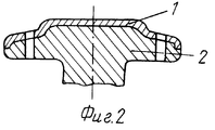
На фиг. 1 изображен разрез контакта с плоским дугогасящим участком; на фиг. 2 изображен разрез контакта с конусообразным дугогасящим участком; на фиг.3 изображен общий вид контакта с дугообразными пазами. In FIG. 1 shows a section through a contact with a flat arc suppression section; in FIG. 2 shows a section through contact with a cone-shaped arc suppression section; figure 3 shows a General view of the contact with arched grooves.
Поз. 1 - дугостойкая накладка; поз. 2 - медное основание контакта. Pos. 1 - arc-resistant pad; pos. 2 - copper base of the contact.
Использование изобретения по сравнению с прототипом позволяет повысить отключающую способность вакуумных дугогасительных камер и снизить норму расхода дорогостоящего дугогасительного материала. The use of the invention in comparison with the prototype allows to increase the breaking capacity of the vacuum interrupter chambers and reduce the consumption rate of expensive interrupter material.
Claims (1)
Priority Applications (1)
| Application Number | Priority Date | Filing Date | Title |
|---|---|---|---|
| RU94010714A RU2105373C1 (en) | 1994-03-25 | 1994-03-25 | Vacuum arc-control chamber contact |
Applications Claiming Priority (1)
| Application Number | Priority Date | Filing Date | Title |
|---|---|---|---|
| RU94010714A RU2105373C1 (en) | 1994-03-25 | 1994-03-25 | Vacuum arc-control chamber contact |
Publications (2)
| Publication Number | Publication Date |
|---|---|
| RU94010714A RU94010714A (en) | 1995-10-27 |
| RU2105373C1 true RU2105373C1 (en) | 1998-02-20 |
Family
ID=20154037
Family Applications (1)
| Application Number | Title | Priority Date | Filing Date |
|---|---|---|---|
| RU94010714A RU2105373C1 (en) | 1994-03-25 | 1994-03-25 | Vacuum arc-control chamber contact |
Country Status (1)
| Country | Link |
|---|---|
| RU (1) | RU2105373C1 (en) |
Cited By (1)
| Publication number | Priority date | Publication date | Assignee | Title |
|---|---|---|---|---|
| RU2156514C1 (en) * | 1999-11-05 | 2000-09-20 | Малаховский Сергей Иванович | Vacuum arc chute |
Citations (1)
| Publication number | Priority date | Publication date | Assignee | Title |
|---|---|---|---|---|
| SU1394258A1 (en) * | 1986-01-13 | 1988-05-07 | Организация П/Я Р-6308 | Method of applying contact coating onto the contact-part of vacuum high-voltage ferreed switch |
-
1994
- 1994-03-25 RU RU94010714A patent/RU2105373C1/en active
Patent Citations (1)
| Publication number | Priority date | Publication date | Assignee | Title |
|---|---|---|---|---|
| SU1394258A1 (en) * | 1986-01-13 | 1988-05-07 | Организация П/Я Р-6308 | Method of applying contact coating onto the contact-part of vacuum high-voltage ferreed switch |
Non-Patent Citations (1)
| Title |
|---|
| US, патент, 4324960, кл.200 - 144, 1982. * |
Cited By (1)
| Publication number | Priority date | Publication date | Assignee | Title |
|---|---|---|---|---|
| RU2156514C1 (en) * | 1999-11-05 | 2000-09-20 | Малаховский Сергей Иванович | Vacuum arc chute |
Similar Documents
| Publication | Publication Date | Title |
|---|---|---|
| GB1104674A (en) | Circuit breaker apparatus | |
| US4438307A (en) | Electric vacuum switch | |
| CA1239180A (en) | Axial magnetic field vacuum-type circuit interrupter | |
| RU2105373C1 (en) | Vacuum arc-control chamber contact | |
| US3156803A (en) | Circuit interrupter having uniformly spaced spiral arc runners in a confined atmosphere for improved arc voltage control | |
| US3281563A (en) | Vacuum switch having an improved electrode tip | |
| JPH04312715A (en) | Electric contact of switch | |
| US3348012A (en) | Contact structure for an electric vacuum switch | |
| RU94010714A (en) | CONTACT VACUUM ARMOR CAMERA AND METHOD OF ITS MANUFACTURE | |
| US4142081A (en) | Contact system for high-voltage power circuit breakers | |
| SU964765A1 (en) | Vacuum switching apparatus contact | |
| RU2158035C2 (en) | Contact system of vacuum arc chute | |
| EP0865057B1 (en) | Vacuum switching device | |
| CN1331173C (en) | Low voltage circuit breaker | |
| PL118529B1 (en) | System of contacts for low voltage vacuum contactorora | |
| SU1201916A1 (en) | Fuse | |
| SU828243A1 (en) | Liquid-metal contact assembly | |
| SU1647680A1 (en) | Self-restoring current limiter | |
| RU1778804C (en) | Vacuum arc blow-out chamber | |
| RU2105374C1 (en) | Vacuum switch | |
| JP2883754B2 (en) | Gas circuit breaker for electric power | |
| RU2092926C1 (en) | Vacuum switch | |
| EP0057452B1 (en) | Arc restricting device for a circuit breaker | |
| JPS63313441A (en) | circuit breaker | |
| JPH0479090B2 (en) |