RU2105103C1 - Filter - Google Patents
Filter Download PDFInfo
- Publication number
- RU2105103C1 RU2105103C1 RU95117363A RU95117363A RU2105103C1 RU 2105103 C1 RU2105103 C1 RU 2105103C1 RU 95117363 A RU95117363 A RU 95117363A RU 95117363 A RU95117363 A RU 95117363A RU 2105103 C1 RU2105103 C1 RU 2105103C1
- Authority
- RU
- Russia
- Prior art keywords
- plate
- drain hole
- mesh
- strip
- filter according
- Prior art date
Links
Images

Landscapes
- Sink And Installation For Waste Water (AREA)
Abstract
Description
Изобретение относится к санитарно-техническому оборудованию, в частности, к устройствам, обеспечивающим устранение попадания мусора через сливное отверстие умывальника, ванны, кухонной мойки и т.п. в трубопровод. The invention relates to sanitary equipment, in particular, to devices for eliminating the ingress of debris through the drain hole of the washbasin, bathtub, kitchen sink, etc. into the pipeline.
Известна вставка в сливное отверстие, предотвращающая попадание в сливные трубы раковин и ванн мелких загрязнений. Вставка содержит сборник для удержания мусора, стенки которого имеют прорези и основные центрирующие элементы, и связанный со сборником опорный элемент с прорезями для удержания сборника в отверстии сливного устройства. Сборник вставки снабжен дополнительными упругодеформируемыми центрирующими элементами для обеспечения самоустановки в отверстии сливного устройства, при этом часть прорезей опорного элемента сообщена с прорезями сборника с образованием каналов для выхода жидкости, а опорный элемент выполнен в виде диска. Указанное устройство является наиболее близким аналогом данного изобретения. Known insert in the drain hole, preventing ingress into the drain pipes of sinks and bathtubs of small contaminants. The insert contains a collector for holding debris, the walls of which have slots and main centering elements, and a support element connected with the collector with slots for holding the collector in the opening of the drain device. The insert collector is equipped with additional elastically deformable centering elements for self-installation in the hole of the drain device, while some of the slots of the support element are in communication with the slots of the collector with the formation of channels for fluid outlet, and the support element is made in the form of a disk. The specified device is the closest analogue of the present invention.
Недостатком известной фильтрующей вставки является то, что она пропускает волосы, которые могут образовывать в трубопроводе пробки. A disadvantage of the known filter insert is that it passes hair that can form plugs in the conduit.
Задача изобретения состоит в том, чтобы устранить недостатки, присущие известным фильтрам и обеспечить исключение засорения сливного отверстия и образование пробок из волос и т.п. в трубопроводе. The objective of the invention is to eliminate the disadvantages inherent in known filters and to ensure that clogging of the drain hole and the formation of plugs from the hair, etc. in the pipeline.
Эта задача достигается тем, что фильтр для улавливания мусора в сливных устройствах, включающий перфорированную пластинку для пропуска воды, соединенную с разрезной в продольном направлении трубкой, установленной с возможностью изменения ее диаметра в соответствии с диаметром сливного отверстия, снабжен дополнительной сеткой, отверстия которой меньше отверстий пластинки, причем пластинка выполнена с зажимами для крепления сетки, а трубка жестко прикреплена к пластинке в одной или двух точках и выполнена в верхней части с вырезами для стока воды между трубкой и пластинкой. This task is achieved in that the filter for trash collection in drainage devices, including a perforated plate for water passage, connected to a longitudinally split pipe installed with the possibility of changing its diameter in accordance with the diameter of the drain hole, is equipped with an additional mesh, the holes of which are smaller than the holes the plate, and the plate is made with clamps for attaching the mesh, and the tube is rigidly attached to the plate at one or two points and is made in the upper part with cutouts for water flow between the tube and the plate.
При этом, пластинка выполнена из металлической фольги, а зажим выполнен в виде отгиба краев пластинки на 180o в направлении наружной поверхности пластинки.Moreover, the plate is made of metal foil, and the clamp is made in the form of a limb of the edges of the plate 180 o in the direction of the outer surface of the plate.
При этом, пластинка выполнена из резины, а зажим для крепления сетки выполнен в виде изогнутой вдвое стальной полоски. At the same time, the plate is made of rubber, and the clamp for attaching the mesh is made in the form of a double-curved steel strip.
При этом, дополнительная сетка закреплена по периметру пластинки со стороны сливного отверстия. At the same time, an additional mesh is fixed around the perimeter of the plate from the side of the drain hole.
При этом, пластинка выполнена с вертикальными ребрами жесткости для образования зазора между пластинкой и поверхностью мойки. Moreover, the plate is made with vertical stiffeners to form a gap between the plate and the surface of the sink.
При этом, между пластинкой и сеткой закреплены стойки с образованием зазора для стока воды в сливное отверстие. At the same time, racks are fixed between the plate and the grid with the formation of a gap for the drain of water into the drain hole.
Перфорированная пластина выполняется из металлической фольги или резины. Площадь отверстий пластинки по размеру превышает сливное отверстие спускного устройства. Пластина выполнена с двумя зажимами, расположенными друг против друга. За счет отгиба краев пластинки дополнительно вниз и создания вертикальных ребер жесткости под ней из материала, не вырезанного из пластинки при изготовлении отверстий, создается зазор между пластинкой и поверхностью мойки. Вследствие этого размер пластинки с сеткой неограниченно можно увеличивать, увеличивая тем самым площадь задержания мусора. Дополнительная сетка закреплена по периметру пластинки со стороны сливного отверстия. Отверстия сетки меньше отверстия пластинки и сливного отверстия спускного устройства. Между пластинкой и сеткой закреплены стойки с образованием зазора для стока воды в сливное отверстие. Сетка задерживает даже волосы, легко вынимается, чистится или заменяется, защищает трубопровод от попадания в него волос, ветоши, мелкого и т.д., а наличие большей плоскости перфорированной пластинки с сеткой обеспечивает быстрый сток воды, причем чем больше площади пластины и сетки, тем больше не требуется чистка или замена последней. Сетка изготовлена из синтетического или металлического материала, причем края синтетической сетки могут быть оплавлены во избежание отсоединения волокон. The perforated plate is made of metal foil or rubber. The area of the holes of the plate in size exceeds the drain hole of the drain device. The plate is made with two clamps located opposite each other. By bending the edges of the plate further down and creating vertical stiffeners under it from material not cut from the plate when making holes, a gap is created between the plate and the washing surface. As a result of this, the size of the plate with the mesh can be increased unlimitedly, thereby increasing the area of garbage collection. An additional mesh is fixed around the perimeter of the plate from the side of the drain hole. The mesh holes are smaller than the plate hole and drain outlet of the drain device. Between the plate and the grid, racks are fixed with a gap for the drainage of water into the drain hole. The mesh even retains hair, can be easily removed, cleaned or replaced, protects the pipeline from hair, rags, small, etc., and the presence of a larger plane of a perforated plate with a mesh ensures a quick flow of water, and the larger the area of the plate and mesh, the more cleaning or replacement of the latter is not required. The mesh is made of synthetic or metallic material, and the edges of the synthetic mesh can be melted to prevent the fibers from detaching.
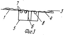
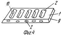
Изобретение иллюстрируется чертежами. На фиг. 1 изображен фильтр, общий вид (в аксонометрии), на фиг. 2 изображена перфорированная пластинка (в аксонометрии), на фиг. 3 изображен узел крепления разрезной трубки перфорированной пластинки с дополнительной сеткой над сливным отверстием, на фиг. 4 изображен вариант выполнения перфорированной пластинки. The invention is illustrated by drawings. In FIG. 1 shows a filter, a general view (in perspective view), in FIG. 2 shows a perforated plate (in a perspective view), in FIG. 3 shows the attachment site of a split tube of a perforated plate with an additional mesh over a drain hole, FIG. 4 shows an embodiment of a perforated plate.
Фильтр состоит из перфорированной пластины 1, перфорации или отверстия 2 в пластинке 1 могут быть выполнены разной формы в виде щелей или круглые. Пластинка 1 выполнена с отгибом краев на 180o с двух противоположных сторон с образованием зажимов 3 выполняющих роль держателей дополнительной сетки 4. Снизу к пластинке 1 прикреплена трубка 5 с разрезом 6 в продольном направлении, позволяющим изменять диаметр трубки по размеру сливного отверстия. Трубка 5 прикреплена к пластинке 1 жестко в двух или более точках 7 и имеет вырезы 8 в верхней части для стока воды между трубкой и пластинкой.The filter consists of a perforated plate 1, perforations or
На фиг. 4 изображен вариант пластинки 1. Все края пластинки отогнуты вниз и выполнены с боковыми отверстиями на отогнутых участках 9. Кроме этого, пластинка 1 дополнена вертикальными ребрами жесткости 10 для образования зазора между пластинкой и поверхностью мойки, ванны, умывальника для свободного стока воды в сливное отверстие. Ребра жесткости эффективно располагать радиально к сливному отверстию, а в параллельных ребрах жесткости 10 на фиг. 4 должны быть сквозные отверстия (проволочная щетка и т.п.). Пластинка 1 своей сплошной поверхностью не должна прилегать к краю сливного отверстия. С этой же целью в трубке 5 сделаны вырезы 8 или к пластинке 1 в местах 7 осуществлено соединение с трубкой 5 с помощью прочных стоек (проволок) для создания зазора для стока воды в сливное отверстие, чтобы избежать торможения потока стенками трубки-кольца 5 и прижима пластинки 1 столбом жидкости к сливному отверстию раковины. In FIG. 4 shows a variant of the plate 1. All edges of the plate are bent down and made with side holes in the
Возможно использование сеток размером, соответствующим размеру мойки. При этом, сетка крепится к мойке липкой лентой. Края ее приподняты вдоль стенок мойки и по углам скреплены. В таком случае вода со всех сторон свободно перемещается к сливному отверстию, а мусор задерживается в любых местах сетки. Сетки из более жестких материалов удобны тем, что не требуют крепления к мойке липкой лентой, легко вынимаются для чистки. It is possible to use nets with a size corresponding to the size of the sink. At the same time, the grid is attached to the sink with adhesive tape. Its edges are raised along the walls of the sink and fastened at the corners. In this case, water from all sides freely moves to the drain hole, and debris is retained in any place of the grid. Grids made of more rigid materials are convenient in that they do not require attachment to the sink with adhesive tape, they are easily removed for cleaning.
Для сеток меньшего размера между синтетической сеткой и перфорированной пластинкой целесообразно устройство металлической редкой сетки, при этом металлическая сетка может быть гофрированной. For smaller grids between the synthetic mesh and the perforated plate, it is advisable to arrange a rare metal mesh, while the metal mesh can be corrugated.
В случае, когда пластинка 1 изготавливается из резины, стали в роли зажимов используют изогнутые стальные полоски, изгибающие края пластины с внешней стороны. In the case when the plate 1 is made of rubber, steel in the role of clamps use curved steel strips, bending the edges of the plate from the outside.
При использовании изобретения сливное отверстие не засоряется, исключается образование пробок из волос в трубопроводах. When using the invention, the drain hole is not clogged, the formation of plugs from the hair in the pipelines is excluded.
Claims (6)
Priority Applications (1)
| Application Number | Priority Date | Filing Date | Title |
|---|---|---|---|
| RU95117363A RU2105103C1 (en) | 1995-10-06 | 1995-10-06 | Filter |
Applications Claiming Priority (1)
| Application Number | Priority Date | Filing Date | Title |
|---|---|---|---|
| RU95117363A RU2105103C1 (en) | 1995-10-06 | 1995-10-06 | Filter |
Publications (2)
| Publication Number | Publication Date |
|---|---|
| RU95117363A RU95117363A (en) | 1997-10-27 |
| RU2105103C1 true RU2105103C1 (en) | 1998-02-20 |
Family
ID=20172765
Family Applications (1)
| Application Number | Title | Priority Date | Filing Date |
|---|---|---|---|
| RU95117363A RU2105103C1 (en) | 1995-10-06 | 1995-10-06 | Filter |
Country Status (1)
| Country | Link |
|---|---|
| RU (1) | RU2105103C1 (en) |
Cited By (1)
| Publication number | Priority date | Publication date | Assignee | Title |
|---|---|---|---|---|
| US10874960B2 (en) | 2018-09-06 | 2020-12-29 | Dallas Michael Wagener | Waste pipe material capturing device |
Citations (2)
| Publication number | Priority date | Publication date | Assignee | Title |
|---|---|---|---|---|
| SU1747617A1 (en) * | 1990-11-19 | 1992-07-15 | И.М. Брутер и B.C. Фарбер | Inserted attachment for collecting garbage in liquid discharge systems |
| US5297299A (en) * | 1992-10-16 | 1994-03-29 | Wilson Mary A | Drain hair net |
-
1995
- 1995-10-06 RU RU95117363A patent/RU2105103C1/en active
Patent Citations (2)
| Publication number | Priority date | Publication date | Assignee | Title |
|---|---|---|---|---|
| SU1747617A1 (en) * | 1990-11-19 | 1992-07-15 | И.М. Брутер и B.C. Фарбер | Inserted attachment for collecting garbage in liquid discharge systems |
| US5297299A (en) * | 1992-10-16 | 1994-03-29 | Wilson Mary A | Drain hair net |
Cited By (1)
| Publication number | Priority date | Publication date | Assignee | Title |
|---|---|---|---|---|
| US10874960B2 (en) | 2018-09-06 | 2020-12-29 | Dallas Michael Wagener | Waste pipe material capturing device |
Similar Documents
| Publication | Publication Date | Title |
|---|---|---|
| US6387261B1 (en) | Serviceable filter with bypass | |
| US6797162B2 (en) | Catch basin filter for stormwater runoff | |
| US5397464A (en) | Trough type strainer box | |
| US7725960B2 (en) | Disposable drain filter | |
| US5069781A (en) | Combined floor sink and strainer | |
| US3465885A (en) | Debris collector for water drainage pipes | |
| US5855774A (en) | Storm drain filter | |
| US7005061B1 (en) | Drain filter device | |
| US20210277640A1 (en) | Drain assembly to prevent clogs | |
| US6467995B2 (en) | Self-flushing pipe | |
| RU2105103C1 (en) | Filter | |
| US5437789A (en) | Washing machine lint strainer | |
| US6303032B1 (en) | Portable multi-strainer | |
| JP4984141B2 (en) | Simple installation type filtration device in waterway | |
| JP2003328418A (en) | Drainage piping | |
| US4250037A (en) | Plumbing fixture with integral strainer | |
| KR101933045B1 (en) | Filtering device for drain sewage | |
| KR20080105855A (en) | Trash filter | |
| KR20170079458A (en) | Simple rainwater filter hanging under a grating | |
| KR101116660B1 (en) | A Waste Water Screen Apparatus For A Dainage Pipe | |
| JP3048215B2 (en) | Net bag for grease interceptor | |
| CN207761017U (en) | A kind of rain perforaled strainer device | |
| JPH07286348A (en) | Garbage collecting tool for drain port | |
| JP6984810B2 (en) | Drainage port mesh member | |
| JP4027815B2 (en) | Easy to disassemble and clean |