RU2097339C1 - Method and apparatus for periodically cleaning polluted or waste waters - Google Patents
Method and apparatus for periodically cleaning polluted or waste waters Download PDFInfo
- Publication number
- RU2097339C1 RU2097339C1 RU94027693/35A RU94027693A RU2097339C1 RU 2097339 C1 RU2097339 C1 RU 2097339C1 RU 94027693/35 A RU94027693/35 A RU 94027693/35A RU 94027693 A RU94027693 A RU 94027693A RU 2097339 C1 RU2097339 C1 RU 2097339C1
- Authority
- RU
- Russia
- Prior art keywords
- reactor
- water
- separator
- reactor tank
- tank
- Prior art date
Links
Images
Classifications
-
- C—CHEMISTRY; METALLURGY
- C02—TREATMENT OF WATER, WASTE WATER, SEWAGE, OR SLUDGE
- C02F—TREATMENT OF WATER, WASTE WATER, SEWAGE, OR SLUDGE
- C02F3/00—Biological treatment of water, waste water, or sewage
- C02F3/02—Aerobic processes
- C02F3/12—Activated sludge processes
- C02F3/1236—Particular type of activated sludge installations
- C02F3/1242—Small compact installations for use in homes, apartment blocks, hotels or the like
-
- B—PERFORMING OPERATIONS; TRANSPORTING
- B01—PHYSICAL OR CHEMICAL PROCESSES OR APPARATUS IN GENERAL
- B01D—SEPARATION
- B01D21/00—Separation of suspended solid particles from liquids by sedimentation
- B01D21/24—Feed or discharge mechanisms for settling tanks
- B01D21/2444—Discharge mechanisms for the classified liquid
-
- B—PERFORMING OPERATIONS; TRANSPORTING
- B01—PHYSICAL OR CHEMICAL PROCESSES OR APPARATUS IN GENERAL
- B01D—SEPARATION
- B01D21/00—Separation of suspended solid particles from liquids by sedimentation
- B01D21/24—Feed or discharge mechanisms for settling tanks
- B01D21/245—Discharge mechanisms for the sediments
-
- B—PERFORMING OPERATIONS; TRANSPORTING
- B01—PHYSICAL OR CHEMICAL PROCESSES OR APPARATUS IN GENERAL
- B01D—SEPARATION
- B01D21/00—Separation of suspended solid particles from liquids by sedimentation
- B01D21/30—Control equipment
- B01D21/302—Active control mechanisms with external energy, e.g. with solenoid valve
-
- B—PERFORMING OPERATIONS; TRANSPORTING
- B01—PHYSICAL OR CHEMICAL PROCESSES OR APPARATUS IN GENERAL
- B01D—SEPARATION
- B01D21/00—Separation of suspended solid particles from liquids by sedimentation
- B01D21/30—Control equipment
- B01D21/34—Controlling the feed distribution; Controlling the liquid level ; Control of process parameters
-
- B—PERFORMING OPERATIONS; TRANSPORTING
- B09—DISPOSAL OF SOLID WASTE; RECLAMATION OF CONTAMINATED SOIL
- B09C—RECLAMATION OF CONTAMINATED SOIL
- B09C1/00—Reclamation of contaminated soil
-
- B—PERFORMING OPERATIONS; TRANSPORTING
- B09—DISPOSAL OF SOLID WASTE; RECLAMATION OF CONTAMINATED SOIL
- B09C—RECLAMATION OF CONTAMINATED SOIL
- B09C1/00—Reclamation of contaminated soil
- B09C1/10—Reclamation of contaminated soil microbiologically, biologically or by using enzymes
-
- C—CHEMISTRY; METALLURGY
- C02—TREATMENT OF WATER, WASTE WATER, SEWAGE, OR SLUDGE
- C02F—TREATMENT OF WATER, WASTE WATER, SEWAGE, OR SLUDGE
- C02F1/00—Treatment of water, waste water, or sewage
- C02F1/006—Water distributors either inside a treatment tank or directing the water to several treatment tanks; Water treatment plants incorporating these distributors, with or without chemical or biological tanks
-
- Y—GENERAL TAGGING OF NEW TECHNOLOGICAL DEVELOPMENTS; GENERAL TAGGING OF CROSS-SECTIONAL TECHNOLOGIES SPANNING OVER SEVERAL SECTIONS OF THE IPC; TECHNICAL SUBJECTS COVERED BY FORMER USPC CROSS-REFERENCE ART COLLECTIONS [XRACs] AND DIGESTS
- Y02—TECHNOLOGIES OR APPLICATIONS FOR MITIGATION OR ADAPTATION AGAINST CLIMATE CHANGE
- Y02W—CLIMATE CHANGE MITIGATION TECHNOLOGIES RELATED TO WASTEWATER TREATMENT OR WASTE MANAGEMENT
- Y02W10/00—Technologies for wastewater treatment
- Y02W10/10—Biological treatment of water, waste water, or sewage
Abstract
Description
Изобретение относится к способу и устройству для чередующейся обработки загрязненной и/или сточной воды путем биологической очистки и, если необходимо также с помощью химической очистки. The invention relates to a method and apparatus for alternating treatment of contaminated and / or waste water by biological treatment and, if necessary, also by chemical treatment.
Устройство для этой цели состоит из обычного сепаратора отстоя или уравнительного резервуара и реакционного оборудования, называемого реактором. Процесс очистки основывается на современной технологии, которая в литературе называется системой последовательных периодических реакторов (SBR) (Sequencing Batch Reactor Technology). A device for this purpose consists of a conventional sludge separator or surge tank and reaction equipment called a reactor. The cleaning process is based on modern technology, which is called the Sequencing Batch Reactor Technology (SBR) in the literature.
SBR осуществляется таким образом, что в реакционное оборудование, содержащее активный осадок, загружается загрязненная или сточная вода для ее обработки по определенному циклу, после чего цикл повторяют с новой загрузкой загрязненной воды. В соответствии с известной технологией рабочий цикл обычно можно представить следующим образом:
заполнение оборудования загрязненной водой;
обработка загрязненной воды воздухом (аэрация);
осаждение;
отвод чистой воды; и
отвод избытка осадка (не обязательно при каждом цикле).SBR is carried out in such a way that contaminated or waste water is loaded into the reaction equipment containing the active sludge to treat it according to a specific cycle, after which the cycle is repeated with a new load of contaminated water. In accordance with the known technology, the duty cycle can usually be represented as follows:
filling equipment with contaminated water;
air pollution treatment (aeration);
precipitation;
drainage of clean water; and
removal of excess sediment (not necessary with each cycle).
В соответствии с изобретением технология SBR модифицирована таким образом, что сепаратор для отделения осадка или любой другой уравнительный резервуар, выполнен в сочетании с реактором, посредством чего он должен удерживать вышеуказанный реактор при некотором повышенном давлении. Для этих целей используется воздуходувное оборудование, например, некоторые виды компрессора, или боковой вентилятор. Вышеуказанное воздуходувное оборудование используется:
для обработки активного осадка в реакторном резервуаре воздухом (для аэрации);
для создания повышенного давления в реакторном резервуаре, и это повышенное давление используется для отвода чистой (очищенной) воды из резервуара, а также для отвода активного осадка, например, при рецикле вышеуказанного осадка в сепаратор для осаждения;
для закрывания сливного вентиля между осаждающим сепаратором и реактором;
для смешения дозированных количеств флокулирующих и/или осаждающих химикатов.In accordance with the invention, SBR technology is modified so that a separator for separating sludge or any other equalization tank is made in combination with a reactor, whereby it must hold the above reactor at some elevated pressure. For these purposes, blower equipment is used, for example, some types of compressor, or a side fan. The above blower equipment is used:
for treating active sludge in a reactor vessel with air (for aeration);
to create increased pressure in the reactor tank, and this increased pressure is used to drain clean (purified) water from the tank, as well as to drain active sludge, for example, by recycling the above sludge to a separator for precipitation;
to close the drain valve between the precipitating separator and the reactor;
for mixing dosage amounts of flocculating and / or precipitating chemicals.
Таким образом вышеуказанное воздуходувное оборудование представляет собой основной источник энергии для всей системы и это является основой для простоты и безопасности работы всего процесса и причиной, почему этот процесс приемлем для небольших установок, за которыми только изредка наблюдают. Thus, the above blower equipment is the main source of energy for the entire system and this is the basis for the simplicity and safety of the entire process and the reason why this process is acceptable for small installations, which are only occasionally observed.
Путь, которым в реакторе устанавливают и используют повышенное давление, составляет основу изобретения. В соответствии с настоящим способом в реакторном резервуаре монтируют одну или более напорных труб для отвода чистой (очищенной воды). Нижнее отверстие вышеуказанной трубы или труб устанавливают на уровне, который находится ниже уровня чистой воды после осаждения загрязненной, а верхнее отверстие вышеуказанных труб монтируют вместе с выходным отверстием из реактора, например, вместе с переливным выходным отверстием. Высокий уровень выходного отверстия для чистой воды представляет собой преимущество, которое состоит в том, что чистая вода может стекать к месту окончательной выгрузки без необходимости использования насоса. Кратковременное повышение столба воды в напорной трубе выше уровня жидкости в реакторном резервуаре соответствует необходимому давлению в реакторном резервуаре для выдавливания чистой воды. При последующем открывании соединения между реактором и сепаратором или другим сосудом имеющаяся остаточная разность давлений достаточна для передавливания части избыточного отстоя назад в сепаратор или какое-либо другое место, приемлемое для хранения. The way in which the pressure is set and used in the reactor is the basis of the invention. In accordance with the present method, one or more pressure pipes are mounted in the reactor vessel to drain clean (purified water). The lower hole of the above pipe or pipes is set at a level that is below the level of clean water after sedimentation of contaminated, and the upper hole of the above pipes is mounted together with the outlet from the reactor, for example, together with an overflow outlet. The high level of the clean water outlet is an advantage that clean water can drain to the final discharge site without the need for a pump. A short-term increase in the column of water in the pressure pipe above the liquid level in the reactor vessel corresponds to the required pressure in the reactor vessel to squeeze out clean water. When the connection between the reactor and the separator or another vessel is subsequently opened, the residual pressure difference that is present is sufficient to push part of the excess sludge back into the separator or some other place suitable for storage.
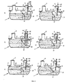
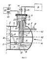
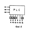
На фиг. 1 схематично показано вертикальное поперечное сечение установки, выполненной в соответствии с изобретением; на фиг. 2 a f поперечное сечение рабочей последовательности, состоящей из шести различных стадий рабочего цикла в установке, выполненной в соответствии с изобретением, которая включает сепаратор для отделения отстоя и реакторный резервуар; на фиг. 3 - устройство реакторного резервуара указанной выше установки, более детально; на фиг. 4 контролирующий элемент установки, схематично; на фиг. 5 - оборудование дозирующее химикаты, которое используется в установке изобретения; на фиг. 6 дозирующее устройство на фиг. 5, в увеличенном масштабе; на фиг. 7 альтернативное исполнение установки на фиг. 1, 2; на фиг 8. альтернативное исполнение устройства на фиг. 3. In FIG. 1 schematically shows a vertical cross section of an apparatus made in accordance with the invention; in FIG. 2 a f is a cross-sectional view of an operating sequence consisting of six different stages of the operating cycle in a plant according to the invention, which includes a separator for separating sludge and a reactor vessel; in FIG. 3 - the device of the reactor tank of the above installation, in more detail; in FIG. 4 control element of the installation, schematically; in FIG. 5 - chemical dosing equipment, which is used in the installation of the invention; in FIG. 6 the metering device of FIG. 5, on an enlarged scale; in FIG. 7 an alternative embodiment of the apparatus of FIG. 12; FIG. 8. An alternative embodiment of the device of FIG. 3.
В простом, но предпочтительном выполнении изобретения установка очистки состоит из единственного резервуара, который с помощью внутренней стенки 2 разделен на две части, большая из которых в этом случае называется сепаратором для отделения осадка 3, а меньшая часть 4 представляет собой реактор 4. В случае больших установок, которые показаны на фиг. 7, может быть предпочтительным использование двух разделительных резервуаров, установленных рядом. Для еще больших установок или для установок другого типа может быть приемлемо использование применявшегося ранее в таких процессах сепаратора для отделения осадка с устройствами для декантирования, причем слив осуществляется в рассматриваемую установку, и установленный далее резервуар будет выполнять функцию уравнительного резервуара. Такие большие установки могут быть смонтированы с использованием нескольких реакторов 4, присоединенных к одному и тому же уравнительному резервуару. Ниже определение "сепаратор для отделения осадка" относится к сепараторному резервуару для отделения осадка/уравнительному резервуару. In a simple but preferred embodiment of the invention, the treatment plant consists of a single tank, which is divided into two parts with the help of the
На фиг. 2 a f схематично показано поперечное сечение предпочтительного воплощения очистительной установки, работающей по заранее определенным стадиям процесса очистки. В представленном простом воплощении изобретения сепаратор для отделения осадка 3 и реактор 4 составляют общий резервуар 1 и отделены друг от друга с помощью внутренней стенки 2. Сепаратор предпочтительно снабжают крышкой 5 для того, чтобы обеспечить возможность откачивания осадка и проведения ремонтно-профилактических работ. Реактор должен иметь плотно прилегающую крышку для создания в реакторе избыточного давления и проведения ремонтно-профилактических работ. Сепаратор для отделения осадка 3 имеет входное отверстие 7 для загрязненной воды из нескольких мест для ее хранения и выходное отверстие в виде шланга или трубы, направленного в реакторную часть 4. Уровень выходного отверстия сепаратора для отделения осадка 3 соответствует предпочтительному объему в резервуаре. Также предпочтительным является наличие расположенного на более высоком уровне выходного отверстия в виде сливного отверстия (не показано), которое может обеспечить прохождение загрязненной воды через реактор в случае очень большого потока загрязненной воды или тогда, когда реактор должен быть опорожнен или очищен. Выходное отверстие 8 реактора 4 выполняется на уровне, который соответствует объему активного осадка, который всегда должен оставаться в реакторе 4 в качестве гарантии безопасной очистки. Выходное отверстие 8 реактора 4 выполняется на уровне, которые соответствует объему активного осадка, который всегда должен оставаться в реакторе 4 в качестве гарантии безопасной очистки. Выходное отверстие выполняется с вентилем V1, который будет описан ниже.In FIG. 2 af schematically shows a cross section of a preferred embodiment of a treatment plant operating in predetermined stages of a cleaning process. In the presented simple embodiment of the invention, the separator for separating
В реакторной части 4 находится напорная труба, которая в изобретении выполняет важную функцию. Следует подчеркнуть, что вышеуказанная напорная труба 9 устанавливается преимущественно вертикально и ее открытый нижний конец находится на уровне, на котором будет находиться чистая (очищенная) вода после стадии осаждения. Верхнее отверстие трубы может быть выполнено в виде сливного отверстия 10, направленного к выходному отверстию 11, через которое чистая вода выходит из установки. Если необходимо, то вышеуказанное выходное отверстие 11 может быть выполнено с вентиляционной трубой 12. При осуществлении воплощения изобретения необходимо верхнее уплотнение напорной трубы 9 и сливного выходного отверстия 10, через которое предпочтительно может проходить выходное отверстие для воздуха 13, регулируемое вентилем V6. С другой стороны, конечно может быть выполнено воздушное выходное отверстие для окружающего воздуха через стенку реактора. В этом случае вентиляционная труба 12 на выходном отверстии для чистой воды может отсутствовать.In the
В еще одном воплощении изобретения, которое не приведено на чертежах, напорная труба 9 может быть выведена наружу. В этом случае нет необходимости предусматривать герметизирующее выходное отверстие 13. In another embodiment of the invention, which is not shown in the drawings, the
Обработка загрузки загрязненной или сточной воды в соответствии с технологией SBR, используемой в изобретении, может быть осуществлена в соответствии с шестью стадиями, показанными на фиг. 2 a f. The treatment of the loading of contaminated or waste water in accordance with the SBR technology used in the invention can be carried out in accordance with the six stages shown in FIG. 2 a f.
Стадия 1.
На фиг. 2 a показано как реактор, содержащий активный осадок 14, наполняется загрязненной водой 15 из сепаратора 3. Вентиль V1 открывается для того, чтобы загрязненная вода попала в реактор, а вентиль V6 открывается для того, чтобы в процессе подачи загрязненной воды из реактора 4 выходил воздух.In FIG. 2 a shows how a reactor containing
Стадия 2.
На следующей стадии, приведенной на фиг. 2 b, показано введение воздуха в реактор 4, который предпочтительно вводится с помощью известного оборудования для аэрации 16 с резиновой мембраной. Процесс подачи воздуха более подробно описывается ниже. Вентиль V6 все еще остается открытым для того, чтобы воздух мог выходить из реактора 4. Вентиль V1 может быть закрыт, или его можно закрыть позднее, например, приблизительно за 15 мин до прекращения аэрации. В последнем случае, который показан на фиг. 2 b, во время рабочего цикла в реактор может поступить больше загрязненной воды. Обычно осаждающее и флокулирующее вещество добавляется в реактор, предпочтительно одновременно с закрытием вентиля V1.In the next step of FIG. 2 b, the introduction of air into the
Стадия 3.
На фиг. 2 c показана следующая стадия цикла, которая представляет собой стадию седиментации. В заявляемых условиях активный осадок 14 оседает на дне реактора 4. In FIG. 2 c shows the next stage of the cycle, which is the stage of sedimentation. In the claimed conditions, the
Стадия 4.
На фиг. 2 d показано каким образом сжатый воздух вводится через вентиль V5 для обеспечения выгрузки уже обработанной воды. Вентиль V6 закрывается и в реакторе 4 создается повышенное давление. Уровень чистой воды в напорной трубе 9 поднимается в зависимости от величины давления в реакционной камере и вытекает через отверстие 11.In FIG. 2 d shows how compressed air is introduced through valve V 5 to ensure the discharge of already treated water. The valve V 6 closes and increased pressure is created in the
Стадия 5.
На фиг. 2 e показана ситуация сразу после открытия вентиля V1. В этом случае в реакторном резервуаре имеет место разность давлений Δ Vp, и это видно из величины, на которую столб воды 17 в напорной трубе выше уровня воды 18 в сепараторе для отделения осадка 3. Эта разность давлений D Vp используется для подачи избытка осадка из реактора 4 назад в сепаратор 3.In FIG. 2 e shows the situation immediately after the opening of valve V 1 . In this case, a pressure difference Δ V p takes place in the reactor vessel, and this can be seen from the value by which the column of
Стадия 6.
На фиг. 2 f показана ситуация, когда разность давлений Vp достигает нуля и вентили V1 и V6 открываются. Когда выполняются эти условия, реактор снова наполняется новой порцией загрязненной воды 15, как это показано на фиг. 2 a, и цикл завершается.In FIG. 2 f shows a situation where the pressure difference V p reaches zero and the valves V 1 and V 6 open. When these conditions are met, the reactor is again filled with a new portion of contaminated
На фиг. 3 более подробно показано строение реакторного резервуара 4. Также на фиг. 3. реакторный резервуар представлен единым с сепаратором и отделен от него внутренней стенкой 2. Соединительный шланг или трубопровод служит для заполнения реактора 4 загрязненной водой на первом этапе (стадия 1). То же соединяющее устройство 8 используется для возвращения избытка суспензии 14 из реактора 4 в сепаратор (стадия 5). Вентиль V1, который в предпочтительном воплощении устанавливается внизу шланга 8, может быть выполнен в виде сливного вентиля, приводимый в работу с помощью сжатого воздуха, что известно в данной области.In FIG. 3 shows in more detail the structure of the
На фиг. 3 также показана напорная труба, сливное отверстие 10, выходное отверстие 11 с трубопроводом для выхода воздуха 12 и крышкой 13 на напорной трубе 9, а также вентиль V1, который закрывается, когда с помощью компрессора или воздуходувного оборудования 19 в реакторе 4 создается избыточное давление. В реакторе также показано приспособление 16 с мембраной для подачи воздуха, в которое подается сжатый воздух через вентиль V4. Также показан контейнер 20 для вызывающих осаждение и флокуляцию химикатов и установленное на его днище дозирующее оборудование, состоящее из двух дозирующих труб. Дозаторами управляют с помощью вентилей V2 и V3. Давление в реакторе поднимают с помощью воздуходувного оборудования через вентиль V5.In FIG. 3 also shows a pressure pipe, a
При проведении процесса очистки необходимо использование индикатора уровня, например, погружного типа, показанного на фиг. 3, с индикаторными стержнями для трех уровней N1, N2 и N3. Индикатор уровня устанавливается в герметично закрытой трубке 21, предпочтительно из PVC пластмассы, внизу которой устанавливается резиновая манжета для выравнивания давления 22. Трубка 21 и резиновая манжета 22 содержит чистую воду, имеет тот же уровень поверхности, что и загрязненная вода 15 в реакторе. Контрольные сигналы индикатора уровня предпочтительно поступают на контролирующий элемент, так называемый PLC. Программируемый логический регулятор. Даже в случае наиболее простого воплощения изобретения программируемый логический регулятор имеет достаточное число входов, выходов и расчетных функций, для того чтобы иметь возможность контролировать различные типы процессов, которые могут представлять интерес с точки зрения технологии SBR. PLC позволяет непосредственно управлять набором электрических воздушных вентилей LV1, LV2, LV3 и LV6, которые в свою очередь, приводят в действие большие вентили V1, V2, V3 и V6. Вентили V4 и V5 предпочтительно приводятся в действие непосредственно PLC.During the cleaning process, it is necessary to use a level indicator, for example, of the submersible type shown in FIG. 3, with indicator rods for three levels N1, N2 and N3. The level indicator is installed in a hermetically sealed tube 21, preferably made of PVC plastic, at the bottom of which a rubber cuff is installed to equalize the
В предпочтительном простом воплощении при разделении для внутреннего использования (на чертежах не показано) функцию индикатора уровня и PLC может выполнять реле времени. In a preferred simple embodiment, when separated for internal use (not shown in the drawings), the level indicator and the PLC can perform a time relay.
На фиг. 3 также показана труба для отбора проб 23, проходящая через крышку 6, и герметизирующая крышка 13, опускающаяся до уровня напорной трубы и обеспечивающая возможность отбирать пробы чистой воды 17, когда эта вода поступает в напорную трубу. Отбор проб можно проводить вручную или автоматически. Установка предпочтительно должна иметь прибор для измерения давления в реакторе, а также в трубопроводе мембранного приспособления для подачи воздуха 16 и славном вентиле V1. Прибор для измерения давления также может быть соединен с PLC для подачи сигнала тревоги при слишком высоком давлении.In FIG. Figure 3 also shows a
Для обеспечения работы реактора воздуходувное оборудование 19 должно обеспечивать давление только приблизительно 0,1 0,2 бара. Это давление, которое соответствует 1 2 м водного столба, является достаточным для того, чтобы вода протекала в реактор и из него. Примером особенно приемлемого для таких целей воздуходувного оборудования является боковой вентилятор, который может обеспечить давление приблизительно 0,3 бара. Этого давления достаточно для проведения аэрации реакторного резервуара, содержащего воду с уровнем 2,5 м, если в этом случае используется аэрирующее устройств с резиновой мембраной, которое работает при давлении 0,05 бар. Этого давления также достаточно для надежного закрывания сливного вентиля V1 при погружении его на глубину приблизительно 1,5 м.To ensure the operation of the reactor,
В предпочтительном воплощении изобретения такое воздуходувное оборудование обеспечивает давление в реакторе 4, когда чистая вода 17 должна быть слита, когда избыток суспензии 14 должен быть возвращен из реактора 4 в сепаратор или какой-либо другой сосуд, когда вода 15 должна быть обработана воздухом, когда сливной вентиль V1 между сепаратором для отделения осадка и реактором 4 должен быть закрыт, а также когда химикаты 20 должны быть смешаны с загрязненной водой 15 в реакторе 4.In a preferred embodiment of the invention, such blower equipment provides pressure in the
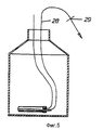
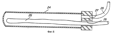
На фиг. 5 и 6 показан пример дозирующего устройства для химикатов, которые образуют осаждающиеся и флокулирующие вещества для загрязненной воды. Дозирующее приспособление выполнено таким образом, чтобы его можно было установить на днище сосуда, содержащего вышеуказанные химикаты. Дозирующее устройство должно иметь внутренний объем, соответствующий количеству, достаточному для обработки порции загрязненной воды в реакторе. Устройство состоит из закрытой трубки 24, содержащей резиновую манжету 25, которая немного выходит за пределы отверстия трубки 24. На патрубке трубки 24 также находится всасывающее отверстие для подачи сжатого воздуха в резиновую манжету 25 и для введения химикатов в камеру трубки 24, когда резиновая манжета 25 не заполнена воздухом. Также предусматривается проход 27 для выходного шланга 28, по которому химикаты подаются в загрязненную воду реактора. Когда резиновая манжета 25 наполнена воздухом, она вначале закрывает всасывающее отверстие 26 для химикатов, а затем подает вышеуказанные химикаты в реактор 4 через шланг 28. На шланге 28 может быть смонтировано запирающее приспособление 29 для предупреждения свободного перетекания химикатов в реактор. Количество химикатов, поступающих в загрязненную воду, может контролироваться введением резиновой манжеты 25 на различные расстояния от закрытого конца трубки 24. In FIG. 5 and 6 show an example of a metering device for chemicals that form precipitating and flocculating substances for contaminated water. The dosing device is designed so that it can be installed on the bottom of the vessel containing the above chemicals. The metering device should have an internal volume corresponding to an amount sufficient to handle a portion of contaminated water in the reactor. The device consists of a
В установке в соответствии с описанием воплощения изобретения присутствуют два дозирующих вентиля V2 и V3 (фиг. 3), при этом одна вентильная труба расположена таким образом, чтобы она была пустой, если достигается только уровень N2, а другая вентильная трубка должна быть пустой при достижении уровня N3. Вентили V2 и V3 установлены таким образом, чтобы контролировать такое дозирование. Так как не все виды загрязненной воды нуждаются в химической очистке, и если необходимость в ней отсутствует, дозирование химикатов из процесса исключается.In the installation in accordance with the description of the embodiment of the invention, there are two metering valves V 2 and V 3 (Fig. 3), while one valve pipe is positioned so that it is empty if only level N2 is reached and the other valve pipe must be empty upon reaching level N3. Valves V 2 and V 3 are installed in such a way as to control such dosing. Since not all types of contaminated water need chemical treatment, and if there is no need for it, dosing of chemicals from the process is excluded.
Обычный рабочий цикл изобретения может происходить следующим образом (фиг. 3). The usual working cycle of the invention can occur as follows (Fig. 3).
1. Вентиль V1 открывается с началом рабочего цикла. Вентиль V6 открывается и загрязненная вода из сепаратора для отделения осадка перетекает в реактор до установления в нем уровня N2.1. Valve V 1 opens at the start of the duty cycle. The valve V 6 opens and the contaminated water from the separator to separate the precipitate flows into the reactor until the level N2 is established in it.
2. Аэрация начинается при открывании вентиля V4. Аэрацию обычно проводят в течение приблизительно 2,5 ч. Сливной вентиль V1 может быть закрыт после начала аэрации или немного позднее, однако обычно не позднее, чем за 15-30 мин. до окончания аэрации.2. Aeration starts when valve V 4 is opened. Aeration is usually carried out for approximately 2.5 hours. The drain valve V 1 can be closed after the start of aeration or a little later, but usually no later than 15-30 minutes. until the end of aeration.
3. При закрытом вентиле V1 вводится в действие дозирующий вентиль V3, а при достижении в реакторе уровня N3 активируется вентиль V3, и в воду в реакторе подаются химикаты.3. With the valve V 1 closed, the metering valve V 3 is activated, and when the reactor reaches level N3, valve V 3 is activated and chemicals are supplied to the water in the reactor.
4. Аэрацию прекращают, закрывая вентиль V4, и одновременно с этим также закрывается вентиль V6. В результате начинается стадия осаждения, которая продолжается в течение приблизительно 45 мин.4. Aeration is stopped by closing valve V 4 , and at the same time, valve V 6 is also closed. As a result, a precipitation step begins, which lasts for approximately 45 minutes.
5. Слив чистой воды происходит при введении в реактор сжатого воздуха при открытом вентиле V5, посредством чего создается повышенное динамическое давление. Чистая вода сливается до тех пор, пока в реакторе не установится уровень N1 или в течение заранее установленного времени, после чего вентиль V5 снова закрывается.5. Drain of clean water occurs when compressed air is introduced into the reactor with valve V 5 open, whereby increased dynamic pressure is created. Pure water is drained until the level of N1 is established in the reactor or within a predetermined time, after which the valve V 5 closes again.
6. Сливной вентиль V1 открывается и остаточное повышенное давление, которое в данном контексте называется повышенным статическим давлением, приводит к перемещению активного осадка, называемого избытком осадка, в сепаратор для отделения осадка.6. The drain valve V 1 opens and the residual increased pressure, which in this context is called increased static pressure, leads to the movement of the active sludge, called excess sludge, into the separator to separate the sludge.
Степень безопасности работы установки изобретения очень высока и такая безопасность необходима для небольших установок, на которых невозможно с точки зрения экономики обеспечить непрерывное наблюдение. Механическая работа установки возможна в течение многих лет без соответствующего надзора. С целью обеспечения безопасной работы и для исключения неожиданного разрушения резиновые части сливного вентиля должны проверяться один раз в год. Также предпочтительно осуществлять проверку реактора и удалять при этом отложения на стенках реактора несколько раз в год и также удалять осадок из сепаратора для отделения осадка. The degree of safety of the installation of the invention is very high and such safety is necessary for small installations where it is impossible from an economic point of view to provide continuous monitoring. Mechanical operation of the installation is possible for many years without proper supervision. In order to ensure safe operation and to prevent unexpected destruction, the rubber parts of the drain valve should be inspected once a year. It is also preferable to check the reactor and remove deposits on the walls of the reactor several times a year and also remove sediment from the separator to separate the precipitate.
Очистная установка изобретения хорошо подходит для обработки городской загрязненной воды, собираемой от двух до приблизительно сотни домов. Она также может быть использована для очистки промышленных отходов, для которых требуется биологическая и химическая очистка. Специальная область применения относится к ситуациям, при которых различные количества загрязненной воды появляются в течение различного промежутка времени (дни, недели), например, на туристических базах. В таких местах несколько реакторов могут быть соединены параллельно друг с другом и могут вводиться в работу или выводиться из работы по мере повышения или понижения загрузки загрязненной воды соответственно. Уменьшение ВОХ и уменьшение фосфора может быть рассчитано до приблизительно 90%
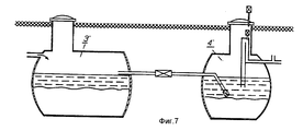
На фиг. 7 показано каким образом установка может быть выполнена из двух элементов, а именно: из сепаратора для отделения осадка 3', который соединяется с одним или несколькими реакторами 4' с помощью трубы 8'.The treatment plant of the invention is well suited for the treatment of urban polluted water collected from two to about a hundred homes. It can also be used to treat industrial wastes that require biological and chemical treatment. A special field of application refers to situations in which different amounts of contaminated water appear over a different period of time (days, weeks), for example, at tourist camps. In such places, several reactors can be connected in parallel with each other and can be put into operation or taken out of operation as the load of contaminated water increases or decreases, respectively. A reduction in BOX and a decrease in phosphorus can be calculated up to approximately 90%
In FIG. 7 shows how the installation can be made of two elements, namely: from a separator for separating sediment 3 ', which is connected to one or more reactors 4' using pipe 8 '.
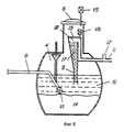
На фиг. 8 показано предпочтительное выполнение напорной трубы 9, имеющей приемник для воды, когда под действием статического давления избыток осадка выдавливается из реактора по сигналу реле времени. Как показано на фиг. 8, также возможно в противоположность или дополнительно к расширенной приемной трубке устанавливать одну или несколько дополнительных напорных труб без сливного выходного отверстия, соединенных напрямую с основной напорной трубой 9. In FIG. 8 shows a preferred embodiment of a
Номера позиций:
1 резервуар;
2 внутренняя стенка;
3 сепаратора для осадка/уравнительный резервуар;
4 реактор;
5 крышка сепаратора;
6 крышка реактора;
7 входное отверстие;
8 выходное отверстие, шланг, труба;
9 напорная труба;
10 сливное отверстие;
11 выходное отверстие;
12 вентиляционная труба;
13 герметизирующая головка;
14 активный осадок в реакторе;
15 загрязненная вода в реакторе;
16 приспособление для аэрации;
17 чистая вода;
18 вода в сепараторе;
19 воздуходувное оборудование;
20 сосуд;
21 герметизирующая трубка;
22 резиновая манжета;
23 трубка для отбора проб;
24 запирающая трубка;
25 резиновая манжета;
26 впускное (всасывающее) отверстие;
27 проход;
28 выходной шланг;
29 запирающее устройство.Item Numbers:
1 tank;
2 inner wall;
3 sediment separators / surge tank;
4 reactor;
5 separator cover;
6 reactor cover;
7 inlet;
8 outlet, hose, pipe;
9 pressure pipe;
10 drain hole;
11 outlet;
12 ventilation pipe;
13 sealing head;
14 active sediment in the reactor;
15 contaminated water in the reactor;
16 device for aeration;
17 clear water;
18 water in the separator;
19 blower equipment;
20 vessel;
21 sealing tube;
22 rubber cuff;
23 sampling tube;
24 locking tube;
25 rubber cuff;
26 inlet (suction) hole;
27 passage;
28 outlet hose;
29 locking device.
Claims (12)
Applications Claiming Priority (3)
| Application Number | Priority Date | Filing Date | Title |
|---|---|---|---|
| SE9103534-5 | 1991-11-28 | ||
| SE9103534A SE468513C (en) | 1991-11-28 | 1991-11-28 | Process and apparatus for batch purification of wastewater |
| PCT/SE1992/000797 WO1993011076A1 (en) | 1991-11-28 | 1992-11-24 | Method and apparatus for batchwise biological and chemical purification of soil water |
Publications (2)
| Publication Number | Publication Date |
|---|---|
| RU94027693A RU94027693A (en) | 1996-04-20 |
| RU2097339C1 true RU2097339C1 (en) | 1997-11-27 |
Family
ID=20384462
Family Applications (1)
| Application Number | Title | Priority Date | Filing Date |
|---|---|---|---|
| RU94027693/35A RU2097339C1 (en) | 1991-11-28 | 1992-11-24 | Method and apparatus for periodically cleaning polluted or waste waters |
Country Status (13)
| Country | Link |
|---|---|
| EP (1) | EP0633866B1 (en) |
| AT (1) | ATE157635T1 (en) |
| CZ (1) | CZ284451B6 (en) |
| DE (1) | DE69222062T2 (en) |
| ES (1) | ES2108139T3 (en) |
| FI (1) | FI107999B (en) |
| GR (1) | GR3025507T3 (en) |
| HU (1) | HU215511B (en) |
| NO (1) | NO941910D0 (en) |
| RU (1) | RU2097339C1 (en) |
| SE (1) | SE468513C (en) |
| SK (1) | SK281134B6 (en) |
| WO (1) | WO1993011076A1 (en) |
Cited By (1)
| Publication number | Priority date | Publication date | Assignee | Title |
|---|---|---|---|---|
| RU2605254C2 (en) * | 2011-09-15 | 2016-12-20 | СТОРМ ДРЕЙН ТЕКНОЛОДЖИЗ, ЭлЭлСи | Device, system and method of processing fluids |
Families Citing this family (5)
| Publication number | Priority date | Publication date | Assignee | Title |
|---|---|---|---|---|
| AU1135599A (en) * | 1997-11-20 | 1999-06-15 | Kurt Gassner | Method and device for the purification of waste water |
| DE10344313B4 (en) | 2003-09-23 | 2018-03-01 | Reinhard Boller | Process and apparatus for the elimination of phosphate in small sewage treatment plants and small sewage treatment plants by means of a simple dosing unit |
| DE102005014301B4 (en) | 2005-03-24 | 2022-08-04 | Reinhard Boller | Device for dosing a precipitant for phosphate elimination in a waste water treatment plant |
| DE202008011241U1 (en) * | 2008-08-22 | 2009-12-31 | Baumann, Markus | Clarifier with outlet |
| DE202008011240U1 (en) * | 2008-08-22 | 2010-01-07 | Baumann, Markus | Clarifier with outlet |
Family Cites Families (1)
| Publication number | Priority date | Publication date | Assignee | Title |
|---|---|---|---|---|
| US4596658A (en) * | 1984-01-30 | 1986-06-24 | Mandt Mikkel G | Sequencing batch reactor decanter systems |
-
1991
- 1991-11-28 SE SE9103534A patent/SE468513C/en not_active IP Right Cessation
-
1992
- 1992-11-24 AT AT92924968T patent/ATE157635T1/en not_active IP Right Cessation
- 1992-11-24 SK SK623-94A patent/SK281134B6/en unknown
- 1992-11-24 RU RU94027693/35A patent/RU2097339C1/en not_active IP Right Cessation
- 1992-11-24 DE DE69222062T patent/DE69222062T2/en not_active Expired - Fee Related
- 1992-11-24 EP EP92924968A patent/EP0633866B1/en not_active Expired - Lifetime
- 1992-11-24 ES ES92924968T patent/ES2108139T3/en not_active Expired - Lifetime
- 1992-11-24 CZ CZ941197A patent/CZ284451B6/en not_active IP Right Cessation
- 1992-11-24 WO PCT/SE1992/000797 patent/WO1993011076A1/en active IP Right Grant
- 1992-11-24 HU HU9401541A patent/HU215511B/en not_active IP Right Cessation
-
1994
- 1994-05-24 NO NO941910A patent/NO941910D0/en unknown
- 1994-05-25 FI FI942420A patent/FI107999B/en active
-
1997
- 1997-11-26 GR GR970403156T patent/GR3025507T3/en unknown
Non-Patent Citations (1)
| Title |
|---|
| SU, авторское свидетельство, 1361115, кл. C 02 F 3/12, 1987. * |
Cited By (1)
| Publication number | Priority date | Publication date | Assignee | Title |
|---|---|---|---|---|
| RU2605254C2 (en) * | 2011-09-15 | 2016-12-20 | СТОРМ ДРЕЙН ТЕКНОЛОДЖИЗ, ЭлЭлСи | Device, system and method of processing fluids |
Also Published As
| Publication number | Publication date |
|---|---|
| ATE157635T1 (en) | 1997-09-15 |
| SE468513C (en) | 1994-05-05 |
| ES2108139T3 (en) | 1997-12-16 |
| CZ119794A3 (en) | 1995-02-15 |
| HUT70792A (en) | 1995-11-28 |
| RU94027693A (en) | 1996-04-20 |
| EP0633866A1 (en) | 1995-01-18 |
| DE69222062D1 (en) | 1997-10-09 |
| NO941910D0 (en) | 1994-05-24 |
| SE468513B (en) | 1993-02-01 |
| DE69222062T2 (en) | 1998-04-23 |
| CZ284451B6 (en) | 1998-12-16 |
| FI942420A0 (en) | 1994-05-25 |
| HU9401541D0 (en) | 1994-09-28 |
| SE9103534L (en) | 1993-02-01 |
| WO1993011076A1 (en) | 1993-06-10 |
| HU215511B (en) | 1999-01-28 |
| SK62394A3 (en) | 1995-05-10 |
| NO941910L (en) | 1994-05-24 |
| SK281134B6 (en) | 2000-12-11 |
| EP0633866B1 (en) | 1997-09-03 |
| FI942420A (en) | 1994-05-25 |
| FI107999B (en) | 2001-11-15 |
| GR3025507T3 (en) | 1998-02-27 |
| SE9103534D0 (en) | 1991-11-28 |
Similar Documents
| Publication | Publication Date | Title |
|---|---|---|
| US4325823A (en) | Wastewater treatment system | |
| EP2258663A1 (en) | Grey water regeneration system | |
| US5665245A (en) | Process for recirculating and purifying waste water from a vehicle washing installation | |
| US3472764A (en) | Sewage treatment method and plant | |
| US5431826A (en) | Automatic grease interceptor with temperature and grease level monitoring | |
| CN107601725A (en) | A kind of container-type garbage percolation liquid treating system and technique | |
| CN107349793A (en) | A kind of system and method that can carry out offline chemical cleaning to MBR film group devices online | |
| RU2097339C1 (en) | Method and apparatus for periodically cleaning polluted or waste waters | |
| US20100326908A1 (en) | Wastewater treatment system | |
| EP0410961B1 (en) | A method and an apparatus for separating solid particles from a liquid | |
| CN108704336A (en) | A kind of closed oilcan dehydration system and its dewatering | |
| JPH0592109A (en) | Method for filtering liquid containing suspended particles | |
| SU1687577A1 (en) | Apparatus for purifying vapour, gas and petroleum containing effluents | |
| CN102269320B (en) | Sewage discharge device for gas cabinet | |
| EP0532951B1 (en) | Method for operating a separator for heavy and light materials and corresponding separator | |
| CN104071926A (en) | V-shaped filter chamber | |
| CN214114989U (en) | Oil absorption mechanism | |
| US3931008A (en) | Apparatus for the treatment of liquid wastes | |
| RU208248U1 (en) | Biological reactor for wastewater treatment | |
| JP2019188369A (en) | Portable water purification system | |
| UA136795U (en) | LIQUID PURIFICATION INSTALLATION | |
| SU1011163A1 (en) | Automatic filtering unit | |
| SU1260463A1 (en) | Method of withdrawing waste water | |
| RU139469U1 (en) | DEVELOPMENT OF BIOLOGICAL CLEANING OF LIQUID FACTION OF PIG MANUS AND MANUSTER-CONTAINING WASTE | |
| CN206308077U (en) | A kind of reverse osmosis concentrated water recycling device |
Legal Events
| Date | Code | Title | Description |
|---|---|---|---|
| MM4A | The patent is invalid due to non-payment of fees |
Effective date: 20031125 |