RU2094635C1 - Microturbine - Google Patents
Microturbine Download PDFInfo
- Publication number
- RU2094635C1 RU2094635C1 RU94017873A RU94017873A RU2094635C1 RU 2094635 C1 RU2094635 C1 RU 2094635C1 RU 94017873 A RU94017873 A RU 94017873A RU 94017873 A RU94017873 A RU 94017873A RU 2094635 C1 RU2094635 C1 RU 2094635C1
- Authority
- RU
- Russia
- Prior art keywords
- rotor
- disk
- annular
- microturbine
- sliding surfaces
- Prior art date
Links
Images
Landscapes
- Magnetic Bearings And Hydrostatic Bearings (AREA)
Abstract
Description
Изобретение относится к турбиностроению, в частности к турбинам малой мощности (микротурбинам) и может быть использовано в пневмошпиделях, микротурбодетандерах, в воздушном и газовом турбоприводе вспомогательных устройств различного назначения. The invention relates to turbine engineering, in particular to low-power turbines (microturbines) and can be used in pneumo-spiders, microturbo-expanders, in the air and gas turbo drive of auxiliary devices for various purposes.
Известна микротурбина, содержащая расположенный в корпусе ротор, выполненный в виде дисков, кольцевые элементы с поверхностями скольжения со смазочными зазорами, выполненную в корпусе полость связанную со смазочными зазорами каналами для подвода сжатого газа. Кольцевыми элементами в данной конструкции микротурбины являются: упорный газостатический подшипник - уплотнение и диск [1]
Однако данная микротурбина не обладает достаточной надежностью, т.к. консольно расположенный диск ротора позволяет ему при определенной частоте вращения испытывать самовозбуждающие колебания в газостатических подшипниках, при этом ось ротора совершает прецессионные круговые движения, т.н. синхронный или полускоростной вихри, что приводит к потере устойчивости ротора и возникновению его вибрации.A microturbine is known comprising a rotor located in the housing made in the form of disks, annular elements with sliding surfaces with lubricating clearances, a cavity formed in the housing and connected to the lubricating clearances by channels for supplying compressed gas. The annular elements in this microturbine design are: thrust gas-static bearing - seal and disk [1]
However, this microturbine does not have sufficient reliability, because the cantilever-located rotor disk allows it to experience self-exciting oscillations in gas-static bearings at a certain rotation frequency, while the rotor axis performs precessional circular movements, the so-called synchronous or half-speed vortices, which leads to a loss of stability of the rotor and the occurrence of its vibration.
Наиболее близкий по технической сущности к предлагаемой является микротурбина, содержащая расположенный в корпусе ротор, выполненный в виде диска, кольцевой выступ с боковыми поверхностями скольжения, образующими с соответствующими поверхностями скольжения кольцевой опорной проточки смазочные зазоры, выполненную в корпусе полость, связанную со смазочными зазорами каналами для подвода сжатого газа, кольцевую паразитную пазуху, выполненную в проточке и соединенную посредством расположенных в диске выхлопных отверстий с лопаточной частью турбины [2]
Данная микротурбина не обладает достаточной надежностью, т.к. для соединения ротора указанной конструкции с приводимыми им потребителями (рабочее колесо компрессора, шлифкруг и др.) необходима деталь в виде барабана, прикрепленная к ротору на диаметре, большем диаметра расположения кольцевого клиновидного выступа, либо выполненная в виде общего бандажа. Причем барабан достаточно тонкостенен вследствие выполнения клинового выступа на сравнительно большом радиусе (чтобы обеспечить достаточную несущую способность газостатического подшипника) либо вследствие очевидности тонкостенности бандажа. Учитывая высокие окружные скорости вращения ротора и, следовательно, значительные центробежные силы, могущие возникнуть в барабане, можно утверждать, что его тонкостенность определяет и достаточно высокие значения напряжений растяжения в барабане, что обеспечивает весьма низкую его прочность и снижает надежность микротурбины.The closest in technical essence to the proposed one is a microturbine containing a rotor located in the housing, made in the form of a disk, an annular protrusion with lateral sliding surfaces, forming lubricating gaps with the corresponding sliding surfaces of the annular support groove, a cavity made in the housing, connected with the lubricating gaps of the channels for compressed gas supply, an annular sinus made in the groove and connected by means of exhaust openings located in the disk with the scapular h Stu turbine [2]
This microturbine does not have sufficient reliability, because To connect the rotor of this design with the consumers brought by it (compressor impeller, grinding wheel, etc.), a drum part is required, attached to the rotor at a diameter larger than the diameter of the ring wedge-shaped protrusion, or made in the form of a common bandage. Moreover, the drum is sufficiently thin-walled due to the implementation of the wedge-shaped protrusion at a relatively large radius (to ensure sufficient bearing capacity of the gas-static bearing) or due to the obviousness of the thin-walled bandage. Given the high circumferential rotor speeds and, consequently, the significant centrifugal forces that can arise in the drum, it can be argued that its thin-walledness also determines rather high values of tensile stresses in the drum, which ensures its very low strength and reduces the reliability of the microturbine.
Кроме того, ротор, приобретая барабан, получает дополнительно одностороннюю консольную нагрузку, причем на диаметре, большем диаметра цапфы. Это обеспечивает условия возникновения синхронного и полускоростного вихря, что приводит к потере устойчивости ротора и возникновению его вибрации. In addition, the rotor, acquiring a drum, receives an additional one-sided cantilever load, moreover, at a diameter greater than the diameter of the journal. This provides the conditions for the occurrence of a synchronous and half-speed vortex, which leads to a loss of stability of the rotor and its vibration.
Постановка потребителей (рабочее колесо компрессора, детандера, шлифкруга и др. ) на свои подшипники сопряжена с выполнением требования сделать барабан гибким, т. к. при жестком барабане для обеспечения равномерности смазочных зазоров подшипников микротурбины и потребителя, учитывая небольшие их размеры и высокие скорости вращения, необходима высокая степень соосности указанных подшипников. Требование соосности выполнить в данных условиях затруднительно, учитывая сборку подшипников на разных посадочных местах. Погрешности же соосности установки подшипников микротурбины и потребителя приводят к нерасчетным условиям работы кромочных областей подшипников и, как следствие, к интенсивному их износу, что резко снижает надежность микротурбины. Setting consumers (impeller of the compressor, expander, grinding wheel, etc.) on their bearings is associated with the requirement to make the drum flexible, because with a hard drum to ensure uniform lubrication clearance of the microturbine and consumer bearings, given their small size and high rotation speeds , a high degree of alignment of these bearings is required. The alignment requirement in these conditions is difficult, given the assembly of bearings at different seats. The alignment errors of the installation of bearings of the microturbine and the consumer lead to off-design conditions of the edge regions of the bearings and, as a result, to their intensive wear, which sharply reduces the reliability of the microturbine.
Конструкция гибкого барабана предопределяет добавку к уже имеющимся значительным по величине напряжениям растяжения знакопеременной составляющей. Последнее понижает прочностные характеристики барабана, что снижает надежность микротурбины. The design of the flexible drum predetermines the addition to the already significant significant tensile stresses of the alternating component. The latter lowers the strength characteristics of the drum, which reduces the reliability of the microturbine.
Задачей, на решение которой направлено предлагаемое решение, является повышение надежности микротурбины. The task to which the proposed solution is directed is to increase the reliability of the microturbine.
Технический результат, который достигается при решении поставленной задачи, выражается в следующем:
ротор значительно меньше подвержен возникновению синхронного и полускоростного вихря и потере устойчивости при нагрузке;
обеспечивается возможность отсутствия дополнительной консольной нагрузки в виде барабана для присоединения потребителей;
обеспечивается более интенсивный отвод газов в лопаточную часть, что повышает несущую способность газостатического подшипника;
обеспечивается уменьшение вредного воздействия появляющихся вторичных течений в межлопаточных каналах на устойчивую работу ротора.The technical result that is achieved when solving the problem is expressed in the following:
the rotor is much less susceptible to the occurrence of a synchronous and half-speed vortex and loss of stability under load;
it is possible that there is no additional cantilever load in the form of a drum for connecting consumers;
more intensive gas removal to the blade part is ensured, which increases the bearing capacity of the gas-static bearing;
provides a reduction in the harmful effects of emerging secondary flows in the interscapular canals on the stable operation of the rotor.
Поставленная задача решается тем, что в микротурбине, содержащей расположенный в корпусе ротор, выполненный в виде диска, кольцевой выступ с боковыми поверхностями скольжения, образующими с соответствующими поверхностями скольжения кольцевой опорной проточки смазочные зазоры, выполненную в корпусе полость, связанную со смазочными зазорами каналами для подвода сжатого газа, кольцевую паразитную пазуху, выполненную в проточке и соединенную посредством расположенных в диске выхлопных отверстий с лопаточной частью турбины, введены следующие изменения: проточка выполнена на торцевой поверхности диска, с поперечным сечением в виде трапеции, ось проточки расположена параллельно оси двигателя, боковые поверхности трапеции являются поверхностями скольжения, а основание перпендикулярно геометрической оси ротора, причем каналы для подвода сжатого газа расположены в выступе, последний выполнен в корпусе, а паразитная пазуха в поперечном сечении ограничена одним из оснований трапеции и концом выступа. The problem is solved in that in a microturbine containing a rotor located in the housing, made in the form of a disk, an annular protrusion with lateral sliding surfaces forming lubricating gaps with the corresponding sliding surfaces of the annular support groove, a cavity formed in the housing, connected with the lubricating gaps of the supply channels of compressed gas, an annular spurious sinus made in the groove and connected by means of exhaust openings located in the disk to the turbine blade part, a trace is introduced Major changes: the groove is made on the end surface of the disk with a trapezoidal cross-section, the axis of the groove is parallel to the motor axis, the lateral surfaces of the trapezoid are sliding surfaces, and the base is perpendicular to the rotor geometric axis, and the channels for supplying compressed gas are located in the protrusion, the latter is made in the body, and the parasitic sinus in cross section is limited to one of the bases of the trapezoid and the end of the protrusion.
Кроме того, микротурбина снабжена дополнительными проточками и дополнительными отверстиями, соединяющими между собой кольцевые паразитные пазухи, а проточки расположены, по крайней мере, на одной торцевой поверхности диска. In addition, the microturbine is equipped with additional grooves and additional holes connecting annular parasitic sinuses, and grooves are located on at least one end surface of the disk.
Поставленная задача решается также тем, что ротор выполнен полым, а в диске выполнены отверстия, соединяющие ближайшую к оси вращения кольцевую паразитную пазуху с внутренней полостью ротора. The problem is also solved by the fact that the rotor is made hollow, and the holes are made in the disk, connecting the ring parasitic sinus closest to the axis of rotation with the inner cavity of the rotor.
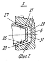
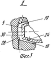
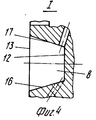
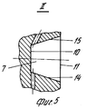
На фиг. 1 изображена предлагаемая микротурбина в разрезе; на фиг. 2 - узел I на фиг. 1; на фиг. 3 узел II на фиг. 1; на фиг. 4 и 5 узлы I и II, в которых отсутствуют кольцевые выступы корпуса. In FIG. 1 shows the proposed microturbine in section; in FIG. 2 - node I in FIG. one; in FIG. 3 node II in FIG. one; in FIG. 4 and 5 nodes I and II, in which there are no annular protrusions of the housing.
Микротурбина содержит диск 1 ротора и центральную вращающуюся часть вал 2, корпус 3, лопаточную часть 4. В корпусе выполнены кольцевые выступы 5 и 6, которые помещены в соответствующие кольцевые опорные проточки 7 и 8, выполненные в диске ротора со стороны обоих торцевых поверхностей диска. Оси указанных проточек параллельны оси микротурбины. Каждая проточка имеет в поперечном сечении форму трапеции с основаниями 10 13 и боковыми сторонами 14 17. Основания перпендикулярны геометрической оси 9 ротора. Боковые стороны образуют поверхности скольжения, между которыми и сопряженными с ними поверхностями скольжения выступов 5 и 6 образованы кольцевые смазочные зазоры 18 21. Корпус 3 и вместе с ним кольцевые выступы 5 и 6 снабжены полостью, состоящей из двух частей 22 и 23 и находящейся под давлением сжатого газа. В кольцевых выступах выполнены каналы 24 27 для подвода сжатого газа из полости в смазочные зазоры. В кольцевых опорных проточках 7 и 8 диска ротора выполнены кольцевые паразитные пазухи 28 и 29, каждая из которых ограничена в поперечном сечении одним из оснований 10 и 12 трапеции и концом 30 и 31 соответствующего выступа. В диске 1 ротора выполнены выхлопные отверстия 32, соединяющие кольцевую паразитную пазуху 29 с лопаточной частью 4. В диске выполнены также дополнительные отверстия 33, соединяющие паразитную пазуху 28 с паразитной пазухой 29. Кроме того в диске выполнены дополнительные отверстия 34, соединяющие паразитную пазуху 28 с внутренней полостью 35 ротора. The microturbine contains the rotor disk 1 and the central rotating part of the shaft 2, the housing 3, the blade part 4. The
Микротурбина работает следующим образом. Microturbine works as follows.
Активный поток рабочего тела, проходя лопаточную часть 4, приводит диск 1 ротора во вращение. Сжатый газ из обоих частей 22 и 23 полости, проходя через каналы 24 27, попадает в кольцевые смазочные зазоры 18 21, обеспечивая несущую способность кольцевых газостатических подшипников микротурбины, образованных поверхностями скольжения. Отработанный из смазочных зазоров газ попадает в кольцевые паразитные пазухи 28 и 29, откуда отводится через выхлопные отверстия 33 и 32 в лопаточную часть 4. При определенных режимах работы газостатического подшипника с паразитной пазухой 29 излишек отработанного газа отводится через отверстия 34 во внутреннюю полость 35 ротора. Диск 1 охватывает подшипники, что в значительной мере снижает возможность появления синхронного вихря. Соединение ротора с приводимыми им потребителями производится с помощью центральной вращающейся части вала 2, так как указанное выше расположение и форма выступов и проточек позволяют это выполнить. Это избавляет ротор от односторонней дополнительной консольной нагрузки и, следовательно, уменьшает возможность появления синхронного и полускоростного вихрей, что приводит к повышению устойчивости ротора. Во вращающихся паразитных пазухах 28 и 29, расположенных в соответствующих проточках 7 и 8, диска 1, возникают центробежные силы, действующие на выходящие из смазочных зазоров 18 21 газы дополнительно к центробежным силам, действующим на выходящие газы в выхлопных отверстиях 32 и 33. Это способствует более интенсивному отводу газов в лопаточную часть 4, что повышает несущую способность газостатических подшипников, образованных поверхностями скольжения выступов и проточек. Расположение паразитной пазухи 29 в диске 1 позволяет выполнить отверстия 32 таким образом, что последние соединяют паразитную пазуху 29 с межлопаточными каналами второй ступени скорости, которая, имея меньшую скорость активного потока и принимая меньшее участие в создании полезной работы, обеспечивает меньшее вредное влияние появляющихся вторичных течений на устойчивую работу ротора. Вторичные же течения в межлопаточных каналах лопаточной части 4 образуются главным образом вследствие того, что газы из выхлопных отверстий 32, встречаясь с активным потоком, тормозят его, повышают его энтропию и обеспечивают неравномерное поле скоростей. Указанное явление усиливает окружную неравномерность потока и, следовательно, газодинамическую неуравновешенность ротора, способствуя тем самым появлению синхронного вихря. The active flow of the working fluid, passing the blade part 4, drives the rotor disk 1 into rotation. Compressed gas from both parts 22 and 23 of the cavity, passing through the
Claims (3)
Priority Applications (1)
| Application Number | Priority Date | Filing Date | Title |
|---|---|---|---|
| RU94017873A RU2094635C1 (en) | 1994-05-13 | 1994-05-13 | Microturbine |
Applications Claiming Priority (1)
| Application Number | Priority Date | Filing Date | Title |
|---|---|---|---|
| RU94017873A RU2094635C1 (en) | 1994-05-13 | 1994-05-13 | Microturbine |
Publications (2)
| Publication Number | Publication Date |
|---|---|
| RU94017873A RU94017873A (en) | 1996-01-20 |
| RU2094635C1 true RU2094635C1 (en) | 1997-10-27 |
Family
ID=20155950
Family Applications (1)
| Application Number | Title | Priority Date | Filing Date |
|---|---|---|---|
| RU94017873A RU2094635C1 (en) | 1994-05-13 | 1994-05-13 | Microturbine |
Country Status (1)
| Country | Link |
|---|---|
| RU (1) | RU2094635C1 (en) |
Cited By (4)
| Publication number | Priority date | Publication date | Assignee | Title |
|---|---|---|---|---|
| WO2000017491A1 (en) * | 1998-09-21 | 2000-03-30 | Bezrukov, Alexandr Mikhailovich | High temperature gas turbine, preferably of a gas turbine engine |
| RU2354836C1 (en) * | 2007-09-24 | 2009-05-10 | Федеральное государственное унитарное предприятие "Центральный институт авиационного моторостроения имени П.И. Баранова" | Miniature gas turbine engine |
| RU2380557C2 (en) * | 2005-11-09 | 2010-01-27 | Онера (Оффис Насьональ Д`Этюд Э Де Решерш Аэроспасьяль) | High-efficiency thermal engine |
| RU2386828C1 (en) * | 2008-08-15 | 2010-04-20 | Федеральное государственное унитарное предприятие "Центральный институт авиационного моторостроения имени П.И. Баранова" | Small-size bypass miniature gas turbine engine |
-
1994
- 1994-05-13 RU RU94017873A patent/RU2094635C1/en active
Non-Patent Citations (1)
| Title |
|---|
| 1. Котляр И.В. и др. Высокоскоростные турбошлифовальные машинки. - Машиностроение, N 2, 1978, с. 44, рис. 1. 2. SU, авторское свидетельство, 515880, кл. F 02 C 7/06, 1976. * |
Cited By (4)
| Publication number | Priority date | Publication date | Assignee | Title |
|---|---|---|---|---|
| WO2000017491A1 (en) * | 1998-09-21 | 2000-03-30 | Bezrukov, Alexandr Mikhailovich | High temperature gas turbine, preferably of a gas turbine engine |
| RU2380557C2 (en) * | 2005-11-09 | 2010-01-27 | Онера (Оффис Насьональ Д`Этюд Э Де Решерш Аэроспасьяль) | High-efficiency thermal engine |
| RU2354836C1 (en) * | 2007-09-24 | 2009-05-10 | Федеральное государственное унитарное предприятие "Центральный институт авиационного моторостроения имени П.И. Баранова" | Miniature gas turbine engine |
| RU2386828C1 (en) * | 2008-08-15 | 2010-04-20 | Федеральное государственное унитарное предприятие "Центральный институт авиационного моторостроения имени П.И. Баранова" | Small-size bypass miniature gas turbine engine |
Similar Documents
| Publication | Publication Date | Title |
|---|---|---|
| US5156528A (en) | Vibration damping of gas turbine engine buckets | |
| RU2419724C1 (en) | Rotor of gas turbine and blade heat machine with such rotor | |
| US5181728A (en) | Trenched brush seal | |
| US5562419A (en) | Shrouded fan blisk | |
| US9726189B2 (en) | Turbocharger and method of manufacturing floating bush | |
| EP1867837B1 (en) | Bucket vibration damper system | |
| US5785492A (en) | Method and apparatus for sealing a gas turbine stator vane assembly | |
| US4767266A (en) | Sealing ring for an axial compressor | |
| JPS60263723A (en) | Compression film damper | |
| KR20040097938A (en) | Vibration damper assembly for the buckets of a turbine | |
| CN115030821B (en) | An aircraft engine bearing cavity comb tooth sealing structure | |
| Armentrout et al. | Rotordynamic characteristics of flexure-pivot tilting-pad journal bearings | |
| EP0100761B1 (en) | Integral bearing system | |
| RU2094635C1 (en) | Microturbine | |
| US3063673A (en) | Centripetal turbine | |
| JP6712873B2 (en) | Seal structure and turbo machine | |
| CN113090556A (en) | Centrifugal compressor and air conditioning equipment | |
| CN211715530U (en) | Dynamic pressure gas bearing and rotary machine | |
| CN111042923A (en) | A rotor system and a micro gas turbine generator set | |
| KR100723040B1 (en) | Bearing assembly for high speed rotor | |
| CN211343140U (en) | Rotor system and micro gas turbine generator set | |
| RU2005890C1 (en) | Stage of turbomachine | |
| JPS58143104A (en) | Leakage preventive device of axial-flow hydraulic machine | |
| JPS58180831A (en) | Gas bearing structure | |
| JPH0218241Y2 (en) |