RU2065373C1 - Water scoop of high-speed vessel - Google Patents
Water scoop of high-speed vessel Download PDFInfo
- Publication number
- RU2065373C1 RU2065373C1 RU9393041682A RU93041682A RU2065373C1 RU 2065373 C1 RU2065373 C1 RU 2065373C1 RU 9393041682 A RU9393041682 A RU 9393041682A RU 93041682 A RU93041682 A RU 93041682A RU 2065373 C1 RU2065373 C1 RU 2065373C1
- Authority
- RU
- Russia
- Prior art keywords
- water
- speed vessel
- water scoop
- interceptor
- vessel
- Prior art date
Links
- XLYOFNOQVPJJNP-UHFFFAOYSA-N water Substances O XLYOFNOQVPJJNP-UHFFFAOYSA-N 0.000 title claims abstract description 10
- 230000000694 effects Effects 0.000 abstract description 2
- 239000000126 substance Substances 0.000 abstract 1
- 230000001939 inductive effect Effects 0.000 description 1
- 210000003127 knee Anatomy 0.000 description 1
- 238000012423 maintenance Methods 0.000 description 1
Landscapes
- Hydraulic Turbines (AREA)
Abstract
Description
Изобретение относится к судостроению и может быть использовано в водометных и гидрореактивных движителях с глубокопогруженной приемной частью. The invention relates to shipbuilding and can be used in water-jet and hydro-jet propulsion with a deep-loaded receiving part.
Известен принятый в качестве ближайшего аналога водозаборник, содержащий проточный трубопровод с поворотными коленами и водозаборным отверстием (А.А. Русецкий. Движители судов с динамическими принципами поддержания. Л. Судостроение, 1978, с.188, 189). Водозаборник имеет большое внешнее сопротивление и гидравлические потери. Known adopted as the closest analogue to the water intake containing a flowing pipe with rotary elbows and a water intake hole (A. A. Rusetskiy. Mover of vessels with dynamic principles of maintenance. L. Sudostroenie, 1978, p.188, 189). The water intake has a large external resistance and hydraulic losses.
Предложенное изобретение предназначено для решения технической задачи снижения сопротивления водозаборника и гидравлических потерь в нем. The proposed invention is intended to solve the technical problem of reducing the resistance of the intake and hydraulic losses in it.
Технический результат достигается тем, что на внутренней кормовой поверхности проточного трубопровода между поворотными коленами в плоскостях его поперечного сечения установлены один или несколько пластинчатых интерцепторов с концевыми шайбами. The technical result is achieved by the fact that on the inner aft surface of the flow pipe between the rotary elbows in the planes of its cross section, one or more plate-type spoilers with end washers are installed.
Сущность изобретения поясняется чертежом, где на фиг.1 дано продольное сечение водозаборника с различными формами поперечного сечения проточного трубопровода. The invention is illustrated in the drawing, where Fig. 1 shows a longitudinal section of a water intake with various cross-sectional shapes of a flow pipe.
Устройство содержит входной патрубок 1, проточный трубопровод 2, поворотные колена 3 и 4, пластинчатые интерцепторы 5 с концевыми шайбами 6, рабочий насос движителя 7. The device includes an inlet pipe 1, a flow line 2, rotary elbows 3 and 4, plate spoilers 5 with end washers 6, a propulsion pump 7.
Устройство работает следующим образом. При работе насоса 7 вода со скоростью движения судна V набегает на интерцептор 5а, при этом перед ним создается зона повышенного давления, а за ним разрежение потока, в связи с чем на внутренней кормовой поверхности трубопровода 2 появляется подъемная сила Рy. Одновременно на интерцепторе 5а возникает сила сопротивления Px, направленная вверх. При этом концевые шайбы 6 устраняют индуктивные потери на интерцепторе. Зона действия положительного и отрицательного давления простирается на 7-10 высот интерцептора перед ним и на 10-14 высот за ним. Поэтому следующий по потоку интерцептор 5в может быть размещен не ближе 17-24 высот интерцептора. Аналогично размещаются и другие интерцепторы. При этом первый интерцептор устанавливается в начале прямолинейного участка трубопровода, а последний не ближе 14 высот до начала верхнего поворотного колена.The device operates as follows. When the pump 7 is operating, water with a vessel speed V runs onto the interceptor 5a, and a pressure zone is created in front of it, followed by a rarefaction of the flow, and therefore a lifting force P y appears on the inner aft surface of the pipeline 2. Simultaneously, an upward resistance force P x arises on the interceptor 5a. In this case, the end washers 6 eliminate inductive losses on the interceptor. The zone of action of positive and negative pressure extends to 7-10 heights of the interceptor in front of him and 10-14 heights behind him. Therefore, the downstream interceptor 5b can be placed no closer than 17-24 heights of the interceptor. Other interceptors are placed similarly. In this case, the first interceptor is installed at the beginning of a straight section of the pipeline, and the last is not closer than 14 heights to the beginning of the upper rotary knee.
Оценим эффект изобретения на примере водометного движителя быстроходного судна с глубокопогруженными крыльями с характерными для реального судна параметрами: скорость судна V 34 узла, (16,2 м/сек). Упор 8300 кгс, диаметр винта 0,91 м, расход воды 6 м3/сек. При этом площадь поперечного сечения трубопровода F 0,37 м2/с учетом поправок 0,45 м2. Длина трубопровода между коленами 4,5 м, высота интерцепторов 2/20 длины поперечного сечения (0,75 м), т.e. h 0,75/20 0,0375 м, а его длина l равна ширине сечения (60 см).Let us evaluate the effect of the invention on the example of a water-jet propulsion of a high-speed vessel with deep-loaded wings with parameters characteristic of a real vessel: vessel speed V 34 knots, (16.2 m / s). Stop 8300 kgf, screw diameter 0.91 m, water consumption 6 m 3 / s. In this case, the cross-sectional area of the pipeline F is 0.37 m 2 /, as amended, 0.45 m 2 . The length of the pipeline between the elbows is 4.5 m, the height of the interceptors is 2/20 of the length of the cross section (0.75 m), i.e. h 0.75 / 20 0.0375 m, and its length l is equal to the width of the section (60 cm).
При этом по длине трубопровода можно разместить три интерцептора с расстоянием между ними L 1,5 м, что соответствует 40h. At the same time, three interceptors with a distance between them of L 1.5 m, which corresponds to 40h, can be placed along the length of the pipeline.
Подъемная сила и сила сопротивления от одного интерцептора будут:
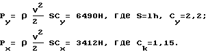
Суммарные силы от трех интерцепторов составят Рy сум 19470 Н, Px сум ![]()
The total forces from the three interceptors will be P y sum 19470 N, P x sum ![]()
Таким образом, сила тяги увеличилась на 24% Сила Px уменьшит массу судна на 1044 кг. С учетом гидравлического сопротивления интерцепторов следует ожидать, что при Сy/Cx 1,9 реальное увеличение тяги составит не менее 15% и повышение КПД до 10%
Устройство просто в исполнении и поэтому возможно его применение на существующих проектах судов.Thus, the thrust increased by 24%. The force P x will reduce the mass of the vessel by 1044 kg. Taking into account the hydraulic resistance of the interceptors, it should be expected that at С y / C x 1.9 a real increase in thrust will be at least 15% and an increase in efficiency up to 10%
The device is simple in execution and therefore it can be used on existing ship projects.
Claims (1)
Priority Applications (1)
| Application Number | Priority Date | Filing Date | Title |
|---|---|---|---|
| RU9393041682A RU2065373C1 (en) | 1993-08-19 | 1993-08-19 | Water scoop of high-speed vessel |
Applications Claiming Priority (1)
| Application Number | Priority Date | Filing Date | Title |
|---|---|---|---|
| RU9393041682A RU2065373C1 (en) | 1993-08-19 | 1993-08-19 | Water scoop of high-speed vessel |
Publications (2)
| Publication Number | Publication Date |
|---|---|
| RU93041682A RU93041682A (en) | 1996-07-20 |
| RU2065373C1 true RU2065373C1 (en) | 1996-08-20 |
Family
ID=20146734
Family Applications (1)
| Application Number | Title | Priority Date | Filing Date |
|---|---|---|---|
| RU9393041682A RU2065373C1 (en) | 1993-08-19 | 1993-08-19 | Water scoop of high-speed vessel |
Country Status (1)
| Country | Link |
|---|---|
| RU (1) | RU2065373C1 (en) |
Cited By (2)
| Publication number | Priority date | Publication date | Assignee | Title |
|---|---|---|---|---|
| RU2188778C2 (en) * | 2000-10-27 | 2002-09-10 | Военно-морская академия им. адмирала флота Советского Союза Н.Г.Кузнецова | Ship's bow |
| RU2228879C2 (en) * | 2002-07-01 | 2004-05-20 | Военно-морская академия им. адмирала флота Советского Союза Н.Г.Кузнецова | Insert-water duct for water-jet propeller |
-
1993
- 1993-08-19 RU RU9393041682A patent/RU2065373C1/en active
Non-Patent Citations (1)
| Title |
|---|
| А.А.Русецкий. Движители судов с динамическими принципами поддержания, Л., Судостроение, 1979, с.188, 189. * |
Cited By (2)
| Publication number | Priority date | Publication date | Assignee | Title |
|---|---|---|---|---|
| RU2188778C2 (en) * | 2000-10-27 | 2002-09-10 | Военно-морская академия им. адмирала флота Советского Союза Н.Г.Кузнецова | Ship's bow |
| RU2228879C2 (en) * | 2002-07-01 | 2004-05-20 | Военно-морская академия им. адмирала флота Советского Союза Н.Г.Кузнецова | Insert-water duct for water-jet propeller |
Similar Documents
| Publication | Publication Date | Title |
|---|---|---|
| US4775341A (en) | Foil system for jet propelled aquatic vehicle | |
| AU723399B2 (en) | Hydraulic system for manoeuvring boats, ships and crafts in general | |
| RU2065373C1 (en) | Water scoop of high-speed vessel | |
| KR102378872B1 (en) | Marine ducted propeller jet propulsion system | |
| RU2065375C1 (en) | Water-jet propeller total-head water scoop | |
| EP3505438A1 (en) | Minimal bow wave system | |
| CN85104618B (en) | Hydraulic ship propelling device with suction inlet | |
| EP2906462B1 (en) | Boat | |
| CN85101991A (en) | Energy saving apparatus for ship by air layers reducing resistance | |
| CA2429204A1 (en) | Propulsion system of a ship, by ejection of water with a pump | |
| US2522883A (en) | Vacuum exhaust tube for connection to marine engines | |
| Brandau | Performance of waterjet propulsion systems-a review of the state-of-the-art | |
| CN210364333U (en) | Jet type drifting boat | |
| CN100441476C (en) | Front-mounted water diversion propeller | |
| RU2065374C1 (en) | Total-head water scoop | |
| RU2185307C2 (en) | Total-head water scoop of water-jet propeller | |
| CN2499333Y (en) | Resistance reducing device for ship | |
| EP4512710A1 (en) | Vortex dynamic propulsion structure | |
| RU2219100C2 (en) | Water-jet propulsion complex with centrifugal pumps | |
| CN206456537U (en) | A kind of water jet propulsion pump water inlet structure | |
| RU2168443C1 (en) | Ship's water-jet propeller | |
| RU2185308C2 (en) | Water scoop for ship's water-jet propeller | |
| US20250066006A1 (en) | Vortex dynamic propulsion structure | |
| RU2183175C2 (en) | Water-jet propulsive complex of ship with centrifugal pumps | |
| AU2023219855A1 (en) | Vortex dynamic propulsion structure |