RU2057504C1 - Device for reproducing and identifying visual images by blind person - Google Patents
Device for reproducing and identifying visual images by blind person Download PDFInfo
- Publication number
- RU2057504C1 RU2057504C1 SU4765879A RU2057504C1 RU 2057504 C1 RU2057504 C1 RU 2057504C1 SU 4765879 A SU4765879 A SU 4765879A RU 2057504 C1 RU2057504 C1 RU 2057504C1
- Authority
- RU
- Russia
- Prior art keywords
- receptor
- unit
- dielectric
- needles
- frequency generator
- Prior art date
Links
- 230000000007 visual effect Effects 0.000 title claims description 12
- 230000001413 cellular effect Effects 0.000 claims abstract description 4
- 230000008447 perception Effects 0.000 claims description 10
- 239000011521 glass Substances 0.000 claims description 2
- 230000003993 interaction Effects 0.000 claims 1
- 239000003086 colorant Substances 0.000 abstract description 2
- 230000000694 effects Effects 0.000 abstract description 2
- 239000000126 substance Substances 0.000 abstract 1
- 239000004020 conductor Substances 0.000 description 2
- 230000035945 sensitivity Effects 0.000 description 2
- 238000004040 coloring Methods 0.000 description 1
- 238000010586 diagram Methods 0.000 description 1
- 238000012544 monitoring process Methods 0.000 description 1
- 230000010355 oscillation Effects 0.000 description 1
- 238000010422 painting Methods 0.000 description 1
- 239000000523 sample Substances 0.000 description 1
- 238000001228 spectrum Methods 0.000 description 1
- 238000010186 staining Methods 0.000 description 1
Images
Landscapes
- Measurement Of The Respiration, Hearing Ability, Form, And Blood Characteristics Of Living Organisms (AREA)
Abstract
Description
Изобретение относится к устройствам для восприятия изображения и опознания зрительных образов слепым человеком и может быть использовано для обучения, оказания помощи и диагностики слепых людей. The invention relates to devices for image perception and recognition of visual images by a blind person and can be used for training, assisting and diagnosing blind people.
Известно устройство для воспpиятия изображения слепым человеком, содержащее рецепторный узел, соединенный через преобразовательный блок с электромагнитной катушкой с вибратором. A device for reproducing an image by a blind person is known, comprising a receptor assembly connected through a converter unit to an electromagnetic coil with a vibrator.
Известно устройство для опознания зрительных образов практически слепыми людьми, содержащее приемную телевизионную систему, электронный блок, блок питания, блок регулировки яркости и контрастности, систему для наблюдения изображения на экране кинескопа, соединительные разъемы и кабели. A device for recognizing visual images by practically blind people, comprising a receiving television system, an electronic unit, a power supply, a brightness and contrast adjustment unit, a system for observing an image on a picture tube screen, connecting connectors and cables.
Недостатком известных технических решений является низкая эффективность восприятия и опознания зрительных образов. A disadvantage of the known technical solutions is the low efficiency of perception and recognition of visual images.
Цель изобретения повышение эффективности восприятия и опознания зрительных образов слепым человеком и расширение функциональных возможностей, позволяющих воспринимать окрашенное изображение. The purpose of the invention is to increase the efficiency of perception and recognition of visual images by a blind person and the expansion of functionality that allows you to perceive a colored image.
Сущность изобретения состоит в том, что устройство для восприятия и опознания зрительных образов слепыми людьми содержит рецепторный узел, который расположен на теле слепого и электрически связан через разъемы, кабели с приемной телевизионной системой, имеющей блок питания, электронный блок, блок регулировки яркости, контрастности и системой для наблюдения изображения на экране кинескопа, на котором расположена ячеистая маска с системой датчиков и усилителей сигнала, электрически связанных с генератором частот, который совместно с рецепторным узлом воздействует на рецепторы кожи слепых людей, увеличивая экстероцептивную чувствительность и эффективность восприятия зрительного образа, за счет окрашивания объекта изображения генератором частот, помогающего слепым людям быстро адаптироваться в окружающей среде, различать темные, светлые и быстродвижущиеся объекты. The essence of the invention lies in the fact that the device for the perception and recognition of visual images by blind people contains a receptor unit that is located on the body of a blind person and is electrically connected through connectors, cables to a television reception system having a power supply, an electronic unit, a brightness, contrast and a system for observing an image on a kinescope screen, on which there is a cellular mask with a system of sensors and signal amplifiers, electrically connected to a frequency generator, which, together with eptornym node acts on receptors in the skin of blind people, increasing the sensitivity and effectiveness of exteroceptive perception of the visual image, due to staining image of an object frequency generator, which helps blind people to quickly adapt to the environment, to distinguish between dark, light and moving images.
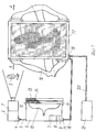
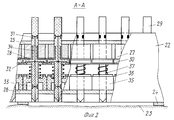
На фиг. 1 изображена функциональная схема работы устройства; на фиг. 2 рецепторный узел, разрез А-А на фиг. 1. In FIG. 1 shows a functional diagram of the operation of the device; in FIG. 2 receptor site, section AA in FIG. 1.
Устройство для восприятия и опознания зрительных образов слепым человеком (см. фиг. 1), содержит приемную телевизионную систему 1, электронный блок 2, который преобразовывает изображение 3 в электрический сигнал, поступающий через соединительный разъем 4, кабель 5 на систему наблюдения изображения 6, имеющую блок питания 7, блок регулировки яркости 8, блок регулировки контрастности 9 и кинескоп 10. Перед экраном кинескопа расположена ячеистая маска 11 с множеством ячеек 12, оборудованных системой фотоэлементных датчиков 13, электрически связанных с системой усилителей 14, от которых электрические сигналы через разъем 15, соединительный кабель 16 поступают на рецепторный узел 17, имеющий элементы крепления 18. Рецепторный узел через разъем 19, кабель 20 электрически связан с генератором низкой частоты 21. Рецепторный узел (см. фиг. 2) выполнен из гибкого корпуса 22, который закреплен к телу слепого человека 23 через прокладки 24. Внутри гибкого корпуса на верхнем и нижнем основании установлены токопроводящие пластины 25, 26 с электромагнитными катушками 27, которые взаимодействуют с множеством стаканов 28, диэлектрических игл 29, имеющих опорную площадку 30, токосъемные контакты 31, 32, 33, связанные между собой проводником 34. Диэлектрические иглы 29 подпружинены к стойке 35, имеющей токопроводящую пластину 36, пружиной 37. A device for the perception and recognition of visual images by a blind person (see Fig. 1), contains a
Работает устройство для восприятия и опознания зрительных образов слепым человеком следующим образом. При помощи элементов крепления 18, рецепторный узел 17 фиксируется к телу слепого человека 23 через прокладки 24 в удобном для него месте, при котором ему можно будет легко прощупывать пальцами на рецепторном узле все контуры негативного изображения рассматриваемого объекта 3 и одновременно ощущать прикосновение к коже диэлектрических игл 29, отображающих позитивное изображение рассматриваемого объекта 3, которое принимается приемной телевизионной системой 1 и электронным блоком 2 преобразуется в электрический сигнал, поступающий через соединительный разъем 4, кабель 5 на систему наблюдения изображения 6, имеющую блок питания 7, блок регулировки яркости 8, блок регулировки контрастности 9 и кинескоп 10. В ячеистой маске 11 яркостный сигнал кинескопа 10, показывающий изображение 3, воспринимается фотоэлементными датчиками 13 и преобразовывается в электрический сигнал, который затем усиливается системой усилителей сигнала 14 и далее через разъем 15, соединительный кабель 16 поступает на рецепторный узел 17, для воспроизведения изображения 3 как в негативной форме, так и в позитивной форме диэлектрическими иглами 29, при помощи электромагнитных катушек 27, взаимодействующих со стаканами 28. По желанию слепого человека, изображение объекта 3 может быть подкрашено в темные, средние и светлые тона или любые цветовые гаммы при помощи генератора 21, выдающего различную частоту колебаний F-1, F-2, F-3, которая устанавливается самим пациентом по желанию как по силе воздействия, так и по степени переносимости тех или иных частот, которые воспринимаются слепым человеком наиболее благоприятно. Электрический сигнал генерируемых частот F-1, F-2, F-3, для цветовой окраски изображения 3 от генератора частот 21, способного выделять любые цветовые гаммы или темные, средние и светлые тона, поступает через токопроводящие пластины 25, 26, 36 рецепторного узла 17 на острие диэлектрической иглы 29 через проводник 34 и токосъемные контакты 31, 32, 33. От положения диэлектрической иглы 29 в гибком корпусе рецепторного узла 17 зависит и частота подаваемого сигнала окраски изображения 3 на тело слепого человека 23. При хорошей экстероцептивной чувствительности слепого человека он может различать прикосновение к коже колющих предметов на расстоянии до одного миллиметра, где с увеличением площади рецепторного узла увеличивается и его разрешающая способность, при этом слепые могут по желанию включать и отключать колющее изображение объекта на теле, чтобы не произошло к нему привыкания, или прощупывать объект изображения пальцами рук, определяя любые цветные гаммы при помощи генератора частот. Данное устройство для восприятия и опознания зрительных образов слепым человеком позволяет повысить эффективность восприятия и опознания зрительных образов, расширить функциональные возможности слепого, позволяет ему воспринимать окрашенное изображение, хорошо адаптироваться в окружающей обстановке и перед близко идущим транспортом, выделять из спектра изображения светлые, темные и средние тона или любые другие цветовые гаммы при помощи генератора частот. A device for the perception and recognition of visual images by a blind person works as follows. Using the
Claims (5)
Priority Applications (1)
| Application Number | Priority Date | Filing Date | Title |
|---|---|---|---|
| SU4765879 RU2057504C1 (en) | 1989-11-30 | 1989-11-30 | Device for reproducing and identifying visual images by blind person |
Applications Claiming Priority (1)
| Application Number | Priority Date | Filing Date | Title |
|---|---|---|---|
| SU4765879 RU2057504C1 (en) | 1989-11-30 | 1989-11-30 | Device for reproducing and identifying visual images by blind person |
Publications (1)
| Publication Number | Publication Date |
|---|---|
| RU2057504C1 true RU2057504C1 (en) | 1996-04-10 |
Family
ID=21483021
Family Applications (1)
| Application Number | Title | Priority Date | Filing Date |
|---|---|---|---|
| SU4765879 RU2057504C1 (en) | 1989-11-30 | 1989-11-30 | Device for reproducing and identifying visual images by blind person |
Country Status (1)
| Country | Link |
|---|---|
| RU (1) | RU2057504C1 (en) |
Cited By (3)
| Publication number | Priority date | Publication date | Assignee | Title |
|---|---|---|---|---|
| RU2187211C2 (en) * | 2000-02-22 | 2002-08-10 | Григорчук Владимир Степанович | Television set |
| RU2213539C2 (en) * | 2000-10-03 | 2003-10-10 | Муниципальное образовательное учреждение "Средняя общеобразовательная школа №19" г.Красноярска | Artificial eye |
| RU2223552C2 (en) * | 2001-12-03 | 2004-02-10 | Федеральное государственное унитарное предприятие "Калужский научно-исследовательский институт телемеханических устройств" | Method for presenting video information |
-
1989
- 1989-11-30 RU SU4765879 patent/RU2057504C1/en active
Non-Patent Citations (2)
| Title |
|---|
| Авторское свидетельство СССР N 226889, кл. A 61F 9/08, 1974. * |
| Авторское свидетельство СССР N 955920, кл. A 61F 9/08, 1980. * |
Cited By (3)
| Publication number | Priority date | Publication date | Assignee | Title |
|---|---|---|---|---|
| RU2187211C2 (en) * | 2000-02-22 | 2002-08-10 | Григорчук Владимир Степанович | Television set |
| RU2213539C2 (en) * | 2000-10-03 | 2003-10-10 | Муниципальное образовательное учреждение "Средняя общеобразовательная школа №19" г.Красноярска | Artificial eye |
| RU2223552C2 (en) * | 2001-12-03 | 2004-02-10 | Федеральное государственное унитарное предприятие "Калужский научно-исследовательский институт телемеханических устройств" | Method for presenting video information |
Similar Documents
| Publication | Publication Date | Title |
|---|---|---|
| US4858617A (en) | Cardiac probe enabling use of personal computer for monitoring heart activity or the like | |
| US5782241A (en) | Sensor device for electrocardiogram | |
| US6658299B1 (en) | Artificial system for vision and the like | |
| US5099856A (en) | Electrode isolation amplifier | |
| US3934267A (en) | Vital phenomenon recording and/or reproducing device | |
| SE9603066D0 (en) | Electrode for tissue stimulation | |
| ES2062440T3 (en) | TRANSCUTANEOUS CONNECTION DEVICE. | |
| JP2004538041A5 (en) | ||
| JP2001170190A (en) | Electromuscular nerve stimulator for measuring muscle response to electrical stimulation pulses | |
| US20210290144A1 (en) | Monitoring device and method for controlling threshold thereof | |
| JPH07170215A (en) | Signal transmission method | |
| RU2057504C1 (en) | Device for reproducing and identifying visual images by blind person | |
| US2327222A (en) | Aiding device for blind persons | |
| JP3323892B2 (en) | Alarm measurement device for personal protection in electromagnetic fields | |
| US4613831A (en) | Audio, ultrasonic and RF noise generator for demonstration of electrical interference | |
| CN110975142A (en) | Wearable arm electric stimulation therapeutic instrument | |
| CN110916660A (en) | Intelligent auricular point information acquisition and diagnosis system | |
| CN107569772B (en) | Multifunctional acupuncture pulse electrotherapeutic instrument | |
| CN111449653A (en) | Wearable brain wave management instrument of intelligence | |
| JP2004089517A (en) | Light emitting electrode device for bioelectric signals | |
| JPS6218176B2 (en) | ||
| CN221431931U (en) | Animal convulsion electric shock instrument with monitoring function | |
| CN217186165U (en) | Brain wave signal detection device with illumination stimulation function | |
| CN220730298U (en) | Oscilloscope and test equipment | |
| CN214971179U (en) | Defibrillation electrode plate, defibrillation equipment and information prompting device |