RU2048503C1 - Coke fire dry extinguishing chamber loading apparatus - Google Patents
Coke fire dry extinguishing chamber loading apparatus Download PDFInfo
- Publication number
- RU2048503C1 RU2048503C1 SU4948384A RU2048503C1 RU 2048503 C1 RU2048503 C1 RU 2048503C1 SU 4948384 A SU4948384 A SU 4948384A RU 2048503 C1 RU2048503 C1 RU 2048503C1
- Authority
- RU
- Russia
- Prior art keywords
- guide
- coke
- funnel
- lever
- chain line
- Prior art date
Links
Images


Landscapes
- Coke Industry (AREA)
Abstract
Description
Изобретение относится к коксохимической промышленности, а именно к устройствам для загрузки камеры сухого тушения кокса. The invention relates to the coke industry, in particular to devices for loading a dry quenching chamber for coke.
Известно загрузочное устройство камеры сухого тушения, которое состоит из загрузочного люка, крышки люка, направляющей воронки и механизма для открывания крышки люка и установки воронки над люком. Направляющая воронка размещается на передвижной тележке. В плане направляющая воронка имеет прямоугольную форму. Сверху вниз воронка сужается до размеров отверстия загрузочного люка и в нижней части имеет форму цилиндра [1]
Особенностью этого устройства является то, что во время загрузки происходят значительные выбросы коксовой пыли и газа через зазоры между верхним краем загрузочной воронки и разгрузочным отверстием кузова вагона и между ним краем загрузочной воронки и верхним краем отверстия загрузочного люка.There is a known device for a dry extinguishing chamber, which consists of a loading hatch, a manhole cover, a funnel guide and a mechanism for opening the manhole cover and installing a funnel above the hatch. The guide funnel is placed on a mobile trolley. In plan, the guide funnel has a rectangular shape. From top to bottom, the funnel narrows to the size of the opening of the loading hatch and in the lower part has the shape of a cylinder [1]
A feature of this device is that during loading, significant emissions of coke dust and gas occur through the gaps between the upper edge of the loading funnel and the discharge opening of the car body and between it the edge of the loading funnel and the upper edge of the opening of the loading hatch.
Попытка устранения этого недостатка сделана в устройстве для загрузки коксом камеры сухого тушения [2] Оно включает расположенную над загрузочным люком камеры тушения воронку, опорные тумбы для установки на них кузова коксовозного вагона, нижняя часть кузова коксовозного вагона снабжена открытым снизу кожухом, а между кожухом и воронкой установлена примыкающая к ним торцами вертикальная обечайка, внутренняя полость которой соединена трубопроводом с пылеочистительным устройством. Особенностью этого устройства является сложность точной установки и контакта кожуха и обечайки, что не обеспечивает эффективный отсос выбросов при загрузке. Кроме того, кожух, установленный на кузове коксовозного вагона, в результате термических воздействий от раскаленного кокса деформируется, в результате чего обеспечение контакта кожуха и обечайки с целью образования замкнутой полости еще более усложняется. Из-за перечисленных особенностей и сложности конструкции (необходимость наличия пылеочистительных устройств, трубопроводов), такое устройство не нашло применения на установках сухого тушения кокса. An attempt was made to eliminate this drawback in a device for loading a dry extinguishing chamber with coke [2]. It includes a funnel located above the extinguishing chamber hatch, support stands for installing a coke box car body on them, the lower part of the coke box car body is equipped with a casing open from below, and between the casing and a vertical shell adjacent to their ends is installed with a funnel, the inner cavity of which is connected by a pipe to a dust-cleaning device. A feature of this device is the difficulty of accurate installation and contact of the casing and the shell, which does not provide an effective exhaust suction during loading. In addition, the casing mounted on the body of the coke wagon is deformed as a result of thermal effects from the hot coke, as a result of which the contact between the casing and the shell with the aim of forming a closed cavity is even more complicated. Due to the listed features and design complexity (the need for dust cleaning devices, pipelines), such a device has not found application in dry coke quenching plants.
Задачей изобретения является повышение надежности устройства, сокращение количества вредных выбросов в атмосферу, уменьшение угара кокса. The objective of the invention is to increase the reliability of the device, reducing the amount of harmful emissions into the atmosphere, reducing the fumes of coke.
Задача достигается тем, что загрузочное устройство камеры сухого тушения кокса, включающее платформу с приводом ее горизонтального перемещения, установленную на платформе воронку, имеющую цилиндрическую нижнюю часть, базовые неподвижные опоры для кузова вагона, снабжено подвижной цилиндрической направляющей, охватывающей нижнюю цилиндрическую часть воронки и установленной с возможностью вертикального перемещения относительно воронки и механизмами для опускания и подъема направляющей, при этом механизм опускания направляющей выполнен в виде двух связанных с направляющей и расположенных равномерно по ее периметру вертикальных штанг, верхние концы которых снабжены ограничителем, установленным с возможностью контакта с базовыми неподвижными опорами и кузовом вагона, а механизм подъема содержит, по крайней мере, два механизма возврата, симметрично расположенные относительно оси подвижной цилиндрической направляющей, а механизм возврата выполнен в виде рычага с переменной точкой опоры, находящейся на цилиндрической поверхности опоры, жестко закрепленной на платформе, с нормальным сечением, имеющим форму цепной линии, лежащей в вертикальной плоскости, проходящей через ось подвижной цилиндрической направляющей для кокса, директриса цепной линии совпадает с образующей подвижной цилиндрической направляющей для кокса, а рычаг выполнен в виде прямолинейного стержня, снабженного на одном конце криволинейным элементом, а другой конец связан с контргрузом, при этом другой конец прямолинейного элемента шарнирно связан с подвижной цилиндрической направляющей для кокса на ее образующей, совпадающей с директрисой цепной линии, причем расстояние от места шарнирного соединения для прямой, расположенной вдоль прямолинейного стержня, равно параметру цепной линии. The objective is achieved in that the loading device of the dry coke quenching chamber, including a platform with a drive for its horizontal movement, mounted on a funnel platform having a cylindrical lower part, basic fixed supports for the car body, is equipped with a movable cylindrical guide covering the lower cylindrical part of the funnel and installed with the possibility of vertical movement relative to the funnel and mechanisms for lowering and raising the guide, while the mechanism for lowering the guide flax in the form of two vertical rods connected to the guide and arranged uniformly along its perimeter, the upper ends of which are equipped with a limiter installed with the possibility of contact with the basic fixed supports and the car body, and the lifting mechanism contains at least two return mechanisms symmetrically located relative to axis of the movable cylindrical guide, and the return mechanism is made in the form of a lever with a variable support point located on the cylindrical surface of the support, rigidly fixed to the platform a shape with a normal cross section in the form of a chain line lying in a vertical plane passing through the axis of the movable cylindrical guide for coke, the director of the chain line coincides with the generatrix of the movable cylindrical guide for coke, and the lever is made in the form of a straight rod equipped with a curved at one end element, and the other end is connected with the counterweight, while the other end of the rectilinear element is pivotally connected to a movable cylindrical guide for coke on its generatrix, which coincides with rektrisoy chain line, and the distance from the hinge connection point for a straight line extending along a rectilinear rod, is equal to the parameter of the catenary.
Для получения положительного эффекта используются свойства цепной линии и ее эвольвенты трактрисы. При выполнении механизма возврата в виде рычага с переменной точкой опоры, находящейся на цилиндрической поверхности с нормальным сечением, имеющим форму цепной линии с параметром а, причем расстояние от конца элемента рычага до прямой, расположенной вдоль прямоугольного участка рычага, равно а, конец прямолинейного элемента рычага движется строго по вертикальной прямой. Выполнение механизма возврата в виде рычага с переменной точкой опоры позволяет, как это описано выше, обеспечить движение подвижной цилиндрической направляющей вертикально вверх и, тем самым, выполнить зазор между нижней частью воронки и подвижной цилиндрической направляющей малым по величине (порядка 5-10 мм). При этом уменьшение зазора влечет уменьшение площади нормального сечения канала между нижней частью воронки и подвижной цилиндрической направляющей. Это позволит уменьшить направленное движение газов на металлические поверхности воронки и направляющей, что позволит повысить надежность устройства. Уменьшение газового потока через зазор влечет сокращение количества вредных выбросов в атмосферу (если давление в форкамере выше атмосферного) и уменьшение угара кокса (если давление в форкамере ниже атмосферного, происходит подсос воздуха). Во избежание перекоса конструкции механизм подъема содержит, по крайней мере, два механизма возврата, симметрично расположенные относительно оси подвижной цилиндрической направляющей для кокса. To obtain a positive effect, the properties of the chain line and its involutes of the tractor are used. When executing the return mechanism in the form of a lever with a variable support point located on a cylindrical surface with a normal section, in the form of a chain line with parameter a, the distance from the end of the lever element to the straight line along the rectangular portion of the lever is equal to a, the end of the rectilinear lever element moves strictly in a vertical line. The implementation of the return mechanism in the form of a lever with a variable fulcrum allows, as described above, to ensure the movement of the movable cylindrical guide vertically upwards and, thereby, to make the gap between the lower part of the funnel and the movable cylindrical guide small (about 5-10 mm). Moreover, a decrease in the gap leads to a decrease in the area of the normal section of the channel between the lower part of the funnel and the movable cylindrical guide. This will reduce the directional movement of gases on the metal surface of the funnel and the guide, which will improve the reliability of the device. Reducing the gas flow through the gap leads to a reduction in the amount of harmful emissions into the atmosphere (if the pressure in the prechamber is above atmospheric) and a decrease in coke burnout (if the pressure in the prechamber is below atmospheric, air leaks). To avoid distortion of the structure, the lifting mechanism contains at least two return mechanisms symmetrically located relative to the axis of the movable cylindrical guide for coke.
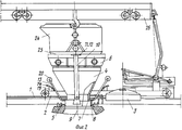
На фиг.1 показан общий вид загрузочного устройства при закрытом положении камеры тушения; на фиг.2 то же, при открытом положении камеры тушения; на фиг.3 механизм возврата. Figure 1 shows a General view of the boot device with the closed position of the fire fighting chamber; figure 2 the same, with the open position of the quenching chamber; figure 3 the return mechanism.
Загрузочное устройство камеры сухого тушения кокса содержит установленную на верху камеру тушения на рельсовых путях 1 платформу 2 с приводом ее горизонтального перемещения и подъема крышки 3 загрузочного люка камеры тушения, воронку 4, смонтированную на платформе. По периметру загрузочного люка расположен кольцевой желоб 5 гидрозатвора. На верху камеры расположены базовые неподвижные опоры 6 для установки на них кузова вагона для раскаленного кокса. Нижнюю цилиндрическую часть 7 воронки 4 охватывает подвижная цилиндрическая направляющая 8 для кокса с осью 9, снабженная механизмом вертикального опускания и механизмом подъема. Механизм опускания направляющей выполнен в виде двух связанных с направляющей 8 и расположенных равномерно по ее периметру вертикальных штанг 10, верхние концы 11 которых снабжены ограничителями 12, установленны с возможностью контакта с неподвижными опорами 6 и кузовом вагона. Механизм подъема содержит, по крайней мере, два механизма возврата, симметрично расположенные относительно оси 9, причем механизм возврата выполнен в виде рычага 13 с переменной точкой опоры, находящейся на цилиндрической поверхности 14 опоры 15, жестко закрепленной на платформе 2 с нормальным сечением, имеющим форму цепной линии 16 с параметром а, лежащей в вертикальной плоскости, проходящей через ось 9 подвижной цилиндрической направляющей 8, директриса цепной линии 16 совпадает с образующей 17 подвижной цилиндрической направляющей 8. Рычаг 13 выполнен в виде прямолинейного стержня 18, снабженного на одном конце криволинейным элементом 19, а другой конец 20 стержня 18 связан с контргрузом 21. Конец 22 криволинейного элемента 19 шарнирно связан с подвижной цилиндрической направляющей 8 на ее образующей 17, совпадающей с директрисой цепной линии 16, расстояние от места шарнирного соединения конца 22 криволинейного элемента 19 до прямой 23, расположенной вдоль прямолинейного стержня 18, равно параметру цепной линии 16. The coke dry quenching chamber loading device comprises a
Для иллюстрации работы загрузочного устройства на фиг.1,2 показаны также кузов 24 вагона для раскаленного кокса с опорной частью 25 и подъемник 26, которые не являются элементами загрузочного устройства. Сборка и монтаж механизма возврата производятся следующим образом. На платформе 2 монтируется опора 15 с цилиндрической поверхностью 14, имеющей в нормальном сечении форму цепной линии 16, чтобы директриса цепной линии сопла с образующей 17 подвижной цилиндрической направляющей 8, а плоскость, в которой расположена цепная линия 16, проходила бы через ось 9 подвижной цилиндрической направляющей 8. Изготавливается рычаг 13, состоящий из прямолинейного стержня 18 и криволинейного элемента 19 с концом 22, причем криволинейный элемент 19 изготавливается так, что расстояние от конца 22 до прямой 23, расположенной вдоль прямолинейного элемента 18, равно параметру цепной линии. Конец 22 элемента 19 шарнирно соединяется с направляющей 8 на ее образующей 17, а прямолинейный стержень 18 рычага 13 опирается на цилиндрическую поверхность 14 опоры 15. Конец 20 прямолинейного стержня 18 связывается с контргрузом 21. To illustrate the operation of the loading device, Fig. 1,2 also shows the
Устройство работает следующим образом. Перед загрузкой камеры тушения раскаленным коксом подъемник 26 с подвешенным на крюках кузовом 24 вагона для раскаленного кокса передвигается по направлению к загрузочному люку камеры сухого тушения кокса, взаимодействует с приводом и, в соответствии с конфигурацией фигурного паза копира производит подъем крышки 3 загрузочного люка и горизонтальное перемещение платформы 2 по рельсовому пути 1. Перемещение платформы 2 происходит до тех пор, пока воронка 4 не установится над отверстием загрузочного люка. После этого кузов 24 с раскаленным коксом опускается и устанавливается на базовые неподвижные опоры 6, при этом опорная часть 25 кузова 24 нажимает на верхние концы 11, снабженные ограничителями 12, вертикальных штанг 10. Вертикальные штанги 10 опускаются под действием веса кузова 24 до тех пор, пока ограничители 12 не войдут во взаимодействие с верхней частью базовых неподвижных опор 6 и не установятся на уровне их верхней части. Вместе со штангами 10 опускается цилиндрическая направляющая 8, жестко связанная со штангами 10, при этом цилиндрическая направляющая 8 перекрывает пространство между основанием нижней цилиндрической части 7 воронки 4 и верхом загрузочного люка, препятствуя выбросам коксовой пыли и газа в атмосферу. Происходит загрузка камеры тушения раскаленным коксом через воронку 4, направляющую 8 и загрузочный люк. При опускании штанг 10 и направляющей 8 конец рычага 13 опускается, а конец 20 с контргрузом 21 поднимается, при этом точка опоры рычага 13 перемещается по поверхности 14 опоры 15, имеющей форму цепной линии 16. После окончания загрузки раскаленного кокса кузов 24 вагона для раскаленного кокса поднимается, при этом механизм подъема, состоящий из механизмов возврата, возвращает направляющую 8 в исходное положение, этот возврат происходит следующим образом: контргруз 21, связанный с концом 20 рычага 13, опускается, конец 22 рычага 13 поднимается, поднимая подвижную цилиндрическую направляющую 8 вместе со штангами 10. Благодаря тому, что точка опоры рычага 13 перемещается по цепной линии 16 и конец 22 рычага, находящийся на образующей 17 подвижной цилиндрической направляющей 8, удален от прямой 23, направленной вдоль прямолинейного стержня 18 рычага 13 на расстояние а, равное параметру цепной линии 16, конец 22 элемента 19 движется вниз строго вертикально, вместе с ним строго вертикально перемещается и направляющая 8. Далее подъемник 26 с подвешенным на крюках кузовом 24 передвигается от загрузочного люка камеры сухого тушения кокса, взаимодействует с приводом и, в соответствии с конфигурацией фигурного паза копира, производит опускание крышки 3 загрузочного люка и горизонтальное перемещение платформы 2 с воронкой 4 по рельсовому пути 1 в исходное положение. Во избежание перекоса конструкции механизм подъема содержит, по крайней мере, два механизма возврата, симметрично расположенные относительно оси 9 подвижной цилиндрической направляющей 8. The device operates as follows. Before loading the extinguishing chamber with hot coke, the
Вследствие того, что механизм возврата выполнен в виде рычага 13 с концом 22, перемещающимся строго вертикально, зазор между направляющей 8 и нижней частью 7 воронки 4 выполняется малым. Вследствие того, что рычаг 13 имеет переменную точку опоры, там отсутствует шарнир, и надежность загрузочного устройства повышается. Вследствие уменьшенного размера зазора сокращаются вредные выбросы в атмосферу и уменьшается угар кокса. Due to the fact that the return mechanism is made in the form of a
Claims (1)
Priority Applications (1)
| Application Number | Priority Date | Filing Date | Title |
|---|---|---|---|
| SU4948384 RU2048503C1 (en) | 1991-06-24 | 1991-06-24 | Coke fire dry extinguishing chamber loading apparatus |
Applications Claiming Priority (1)
| Application Number | Priority Date | Filing Date | Title |
|---|---|---|---|
| SU4948384 RU2048503C1 (en) | 1991-06-24 | 1991-06-24 | Coke fire dry extinguishing chamber loading apparatus |
Publications (1)
| Publication Number | Publication Date |
|---|---|
| RU2048503C1 true RU2048503C1 (en) | 1995-11-20 |
Family
ID=21580803
Family Applications (1)
| Application Number | Title | Priority Date | Filing Date |
|---|---|---|---|
| SU4948384 RU2048503C1 (en) | 1991-06-24 | 1991-06-24 | Coke fire dry extinguishing chamber loading apparatus |
Country Status (1)
| Country | Link |
|---|---|
| RU (1) | RU2048503C1 (en) |
Cited By (2)
| Publication number | Priority date | Publication date | Assignee | Title |
|---|---|---|---|---|
| RU2123024C1 (en) * | 1996-12-24 | 1998-12-10 | Акционерное общество "Новолипецкий металлургический комбинат" | Charging device of set for dry quenching of coke |
| RU2482158C2 (en) * | 2011-01-21 | 2013-05-20 | Государственный институт по проектированию предприятий коксохимической промышленности "Гипрококс" | Loading device of dry coke quenching chamber |
-
1991
- 1991-06-24 RU SU4948384 patent/RU2048503C1/en active
Non-Patent Citations (2)
| Title |
|---|
| 1. Ткачев В.С. и Остапенко М.А. Оборудование коксохимических заводов. М.: Металлургия, 1983, с.253-254. * |
| 2. Авторское свидетельство СССР N 518961, кл. C 10B 39/02, 1977. * |
Cited By (2)
| Publication number | Priority date | Publication date | Assignee | Title |
|---|---|---|---|---|
| RU2123024C1 (en) * | 1996-12-24 | 1998-12-10 | Акционерное общество "Новолипецкий металлургический комбинат" | Charging device of set for dry quenching of coke |
| RU2482158C2 (en) * | 2011-01-21 | 2013-05-20 | Государственный институт по проектированию предприятий коксохимической промышленности "Гипрококс" | Loading device of dry coke quenching chamber |
Similar Documents
| Publication | Publication Date | Title |
|---|---|---|
| US4009081A (en) | Dust arresting apparatus for a coke dry quenching station | |
| GB1562542A (en) | Coke quenching car | |
| RU2048503C1 (en) | Coke fire dry extinguishing chamber loading apparatus | |
| US3785933A (en) | Apparatus for collecting and removing effluent emitted while pushing coke | |
| US3951751A (en) | Pollutant collection system for coke oven discharge operation | |
| KR101464627B1 (en) | Threshold rise-fall apparatus for fire prevention door | |
| GB1589610A (en) | Coke oven batteries | |
| JP2009242447A (en) | Coke charging device for coke dry quenching equipment | |
| KR950002343B1 (en) | Coke feed device for coke dry cooling installation | |
| CA2100870C (en) | Coke feed device for a coke dry cooling installation | |
| JP2006225589A (en) | Coke charging equipment in coke dry fire extinguishing equipment | |
| SU518961A1 (en) | Arrangement for charging coke to dry quenching chamber | |
| CA1077266A (en) | Enclosure for steel converting apparatus | |
| US4141299A (en) | Dumping railway quench car | |
| US4092222A (en) | Top dust collecting apparatus in coke quenching system | |
| US4096040A (en) | Tripper beam | |
| KR102393754B1 (en) | Exhaust fumes collecting apparatus for vehicle | |
| JPS58136689A (en) | Coke dry cooling method and column | |
| CA1086677A (en) | Slatted top quench car | |
| KR910008223B1 (en) | Coke oven gas exhausting | |
| US4312713A (en) | Coke oven gas extraction equipment | |
| US4589465A (en) | Top pour shroud | |
| RU2041914C1 (en) | Charging device of coke dry quenching box | |
| CN209816026U (en) | Dry quenching fixed type loading device | |
| US4462575A (en) | Hood assembly for a metallurgical converter |