RU2039373C1 - Device for interface between computer and tv set - Google Patents
Device for interface between computer and tv set Download PDFInfo
- Publication number
- RU2039373C1 RU2039373C1 SU5022245/24A SU5022245A RU2039373C1 RU 2039373 C1 RU2039373 C1 RU 2039373C1 SU 5022245/24 A SU5022245/24 A SU 5022245/24A SU 5022245 A SU5022245 A SU 5022245A RU 2039373 C1 RU2039373 C1 RU 2039373C1
- Authority
- RU
- Russia
- Prior art keywords
- output
- inputs
- color
- generator
- control input
- Prior art date
Links
- 239000011159 matrix material Substances 0.000 claims abstract description 20
- 238000009434 installation Methods 0.000 claims description 2
- 230000001934 delay Effects 0.000 claims 1
- 230000000694 effects Effects 0.000 abstract description 2
- 239000000126 substance Substances 0.000 abstract 1
- 238000013016 damping Methods 0.000 description 2
- 238000010586 diagram Methods 0.000 description 2
- 238000001228 spectrum Methods 0.000 description 2
- 230000005540 biological transmission Effects 0.000 description 1
- 230000015572 biosynthetic process Effects 0.000 description 1
- 230000000903 blocking effect Effects 0.000 description 1
- 239000003086 colorant Substances 0.000 description 1
- 238000010276 construction Methods 0.000 description 1
- 238000005516 engineering process Methods 0.000 description 1
- 238000005272 metallurgy Methods 0.000 description 1
- 238000000034 method Methods 0.000 description 1
- 238000004377 microelectronic Methods 0.000 description 1
- 239000010453 quartz Substances 0.000 description 1
- 238000010791 quenching Methods 0.000 description 1
- 230000000171 quenching effect Effects 0.000 description 1
- VYPSYNLAJGMNEJ-UHFFFAOYSA-N silicon dioxide Inorganic materials O=[Si]=O VYPSYNLAJGMNEJ-UHFFFAOYSA-N 0.000 description 1
- 230000001629 suppression Effects 0.000 description 1
- 230000007704 transition Effects 0.000 description 1
Images
Landscapes
- Color Television Systems (AREA)
- Processing Of Color Television Signals (AREA)
Abstract
Description
Изобретение относится к компьютерной технике и представляет собой устройство для сопряжения персонального компьютера, в частности совместимого с компьютерами "Х-Спектрум" с используемым в качестве монитора телевизионным приемником системы СЕКАМ. The invention relates to computer technology and is a device for interfacing a personal computer, in particular compatible with X-Spectrum computers, with the SECAM television receiver used as a monitor.
Совместимые с ЭВМ "Х-Спектрум" персональные компьютеры обычно оборудуются интерфейсом подключения к используемому в качестве монитора телевизионному приемнику системы СЕКАМ, содержащим выходы R, G, В кадрового и строчного синхроимпульсов [1] Недостатком такого устройства является необходимость переделки существующих бытовых телевизионных приемников системы СЕКАМ, так как они обычно имеют антенный и видео входы, а входы R, G, В кадрового и строчного синхроимпульсов у них отсутствуют. Personal computers compatible with X-Spectrum computers are usually equipped with an interface for connecting to a SECAM system television receiver used as a monitor, containing R, G, B frames and horizontal sync pulses [1] The disadvantage of this device is the need to remake existing SECAM home television receivers , since they usually have antenna and video inputs, and the R, G, B inputs of the frame and horizontal sync pulses do not exist.
Наиболее близким по технической сущности и достигаемому результату является устройство, содержащее кодирующую матрицу с входами R, G, В и подключенными к ее выходам линией задержки яркостного сигнала и усилителями цветоразностных сигналов, электронный коммутатор, формирователь импульсов цветовой синхронизации, генератор коммутирующих импульсов, устройство гашения, синхрогенератор, генератор поднесущих цветности и двухвходовой смеситель, выход которого является выходом устройства, причем выход линии задержки соединен с первым входом смесителя, первый выход формирователя импульсов цветовой синхронизации связаны с управляющим входом кодирующей матрицы, второй выход формирователя импульсов цветовой синхронизации подключен к первому управляющему входу устройства гашения, первый выход синхрогенератора соединен с управляющим входом формирователя импульсов цветовой синхронизации, второй выход синхрогенератора связан с управляющим входом генератора коммутирующих импульсов, третий выход синхрогенератора подключен к второму управляющему входу устройства гашения, выходы усилителей цветоразностных сигналов соединены с входами электронного коммутатора, выход которого связан с первым управляющим входом генератора поднесущей частоты, выход устройства гашения подключен к второму управляющему входу генератора поднесущей частоты, а выход генератора поднесущей частоты соединен с вторым входом смесителя [2]
В данном устройстве в кодирующую матрицу поступают сигналы основных цветов (красного -R, зеленого -G и синего -В). В кодирующей матрице подключаются сигналы яркости Y и цветоразностные сигналы. В матрице, кроме того, к цветоразностным сигналам примешиваются импульсы цветовой синхронизации из формирователя импульсов цветовой синхронизации. Сигнал яркости Y через каскад задержки сразу проходит в смеситель, а цветоразностные сигналы через усилители поступают на электронный коммутатор. Им управляют импульсы, формируемые в генераторе коммутирующих импульсов. Цветоразностные сигналы появляются на выходе коммутатора поочередно через строку и модулируют по частоте поднесущие в генераторе поднесущих частот. Устройство гашения подавляет поднесущие в модуляторе во время строчных и кадровых гасящих импульсов, кроме времени действия импульсов цветной синхронизации. Синхрогенератор управляет работой всех узлов прибора, в том числе формирователем сигналов R, G, В, который подключен к входам кодирующей матрицы, а также вырабатывает необходимые для формирования полного цветного телевизионного сигнала синхронизирующие кадровые и строчные импульсы.The closest in technical essence and the achieved result is a device containing an encoding matrix with inputs R, G, B and connected to its outputs by a delay line of the luminance signal and color-difference signal amplifiers, an electronic switch, a color burst pulse generator, a switching pulse generator, a blanking device, a sync generator, a chroma subcarrier generator and a two-input mixer, the output of which is the output of the device, the output of the delay line being connected to the first input mixer, the first output of the color burst pulse generator is connected to the control input of the coding matrix, the second output of the color burst pulse generator is connected to the first control input of the damping device, the first output of the sync generator is connected to the control input of the color burst pulse generator, the second output of the sync generator is connected to the control input of the switching generator pulses, the third output of the clock is connected to the second control input of the blanking device, in The outputs of color-difference signal amplifiers are connected to the inputs of an electronic switch, the output of which is connected to the first control input of the subcarrier frequency generator, the output of the damping device is connected to the second control input of the subcarrier frequency generator, and the output of the subcarrier frequency generator is connected to the second input of the mixer [2]
In this device, the signals of the primary colors (red -R, green -G and blue -B) are fed to the coding matrix. In the coding matrix, luminance signals Y and color difference signals are connected. In the matrix, in addition, color-synchronization pulses from the color-pulse generator are mixed with color-difference signals. The luminance signal Y passes immediately through the delay stage to the mixer, and color-difference signals are fed through amplifiers to the electronic switch. It is controlled by pulses generated in the switching pulse generator. Color difference signals appear alternately through the line at the output of the switch and modulate the frequency of the subcarriers in the subcarrier frequency generator. The blanking device suppresses subcarriers in the modulator during horizontal and frame blanking pulses, in addition to the duration of the color synchronization pulses. The sync generator controls the operation of all nodes of the device, including the signal generator R, G, B, which is connected to the inputs of the encoding matrix, and also generates the synchronizing frame and line pulses necessary for generating a full color television signal.
Недостатком известного технического решения являются плохие качественные показатели изображения, обусловленные низкой стабильностью генератора поднесущих частот на основе нестабилизированного блокинг-генератора. Кроме того, все флуктуации средней частоты одной поднесущей немедленно подаются на другую поднесущую, т. к. генератор поднесущих частот известного устройства работает в групповом режиме, что также отрицательно сказывается на качестве изображения. A disadvantage of the known technical solution is the poor image quality due to the low stability of the subcarrier frequency generator based on an unstabilized blocking generator. In addition, all fluctuations in the average frequency of one subcarrier are immediately fed to another subcarrier, since the subcarrier generator of the known device operates in group mode, which also affects image quality.
Технический результат, достигаемый данным предлагаемым изобретением, заключается в улучшении качественных показателей воспроизводимого изображения за счет более точной установки средней частоты поднесущих цветности. The technical result achieved by the present invention is to improve the quality of the reproduced image due to a more accurate setting of the average frequency of the color subcarriers.
Указанный технический результат достигается тем, что в устройство для сопряжения персонального компьютера с телевизионным приемником системы СЕКАМ, содержащее кодирующую матрицу, входы цветовых сигналов которой являются одноименными входами устройства, а выходы соединены соответственно, с входами элемента задержки яркостного сигнала, первый и второй усилители цветоразностных сигналов, первый генератор, управляемый напряжением, электронный коммутатор, формирователь импульсов цветовой синхронизации, генератор коммутирующих сигналов, блок гашения, синхрогенератор и смеситель, причем выход элемента задержки яркостного сигнала соединен с первым входом смесителя, выход которого является выходом устройства, первый выход формирователя импульсов цветовой синхронизации соединен с первым управляющим входом кодирующей матрицы, второй выход подключен к первому управляющему входу блока гашения, второй управляющий вход которого соединен с первым выходом синхронизатора, второй выход которого соединен с управляющим входом формирователя импульсов цветовой синхронизации, а третий выход подключен к управляющему входу генератора коммутирующих импульсов, дополнительно введены два сумматора, второй генератор, управляемый напряжением, ключевой элемент, счетчик и два узла подстройки, каждый из которых содержит последовательно соединенные коммутатор, регистратор и фильтр нижних частот, причем выход первого сумматора соединен с управляющим входом второго генератора, управляемого напряжением, выход второго сумматора соединен с управляющим входом второго генератора, управляемого напряжением, выходы первого и второго генераторов, управляемых напряжением, соединены с входами электронного коммутатора, выход которого через ключевой элемент подключен к второму входу смесителя и к тактовому входу счетчика, разрешающий и установочный входы которого соединены через управляющую шину с четвертым выходом синхрогенератора, связанным через управляющую шину с тактовыми входами регистраторов первого и второго узлов подстройки, выход счетчика подключен к входам компараторов первого и второго узлов подстройки, выходы фильтров нижних частот первого и второго подстройки соединены с первыми входами первого и второго сумматоров соответственно, вторые входы которых соединены с выходами усилителей цветоразностных сигналов, выход блока гашения подключен к второму управляющему входу кодирующей матрицы и к управляющему входу ключевого элемента, выходы генератора коммутирующих импульсов соединены с входами разрешения первого и второго генераторов, управляемых напряжением, а управляющие входы синхронизатора являются входами кадрового и строчного синхроимпульсов устройства. The specified technical result is achieved by the fact that the first and second color-difference amplifiers are connected to the device for interfacing a personal computer with a television receiver of the SECAM system, containing an encoding matrix, the color signal inputs of which are the device inputs of the same name, and the outputs are connected respectively to the inputs of the luminance delay element , the first voltage-controlled oscillator, electronic switch, color burst pulse generator, signal switching generator c, a blanking unit, a sync generator, and a mixer, the output of the luminance delay element being connected to the first input of the mixer, the output of which is the output of the device, the first output of the color burst pulse generator is connected to the first control input of the coding matrix, the second output is connected to the first control input of the blanking unit , the second control input of which is connected to the first output of the synchronizer, the second output of which is connected to the control input of the color-pulse generator, and the third output is connected to the control input of the switching pulse generator, two adders are additionally introduced, a second voltage-controlled oscillator, a key element, a counter and two tuning nodes, each of which contains a switch, a registrar and a low-pass filter connected in series, the output of the first adder connected to the control input of the second voltage-controlled generator, the output of the second adder is connected to the control input of the second voltage-controlled generator, the outputs of the first and voltage controlled oscillators are connected to the inputs of the electronic switch, the output of which through the key element is connected to the second input of the mixer and to the clock input of the counter, the permitting and installation inputs of which are connected through the control bus to the fourth output of the clock connected via the control bus to the clock inputs of the recorders the first and second tuning nodes, the counter output is connected to the inputs of the comparators of the first and second tuning nodes, the outputs of the low-pass filters of the first and watts This adjustment is connected to the first inputs of the first and second adders, respectively, the second inputs of which are connected to the outputs of color-difference signal amplifiers, the output of the blanking unit is connected to the second control input of the coding matrix and to the control input of the key element, the outputs of the switching pulse generator are connected to the resolution inputs of the first and second voltage-controlled generators, and the control inputs of the synchronizer are the inputs of the frame and horizontal sync pulses of the device.
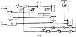
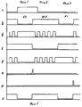
На фиг. 1 приведена структурная схема устройства; на фиг. 2 а-и временные диаграммы, поясняющие работу устройства. In FIG. 1 shows a structural diagram of a device; in FIG. 2 a and temporary diagrams explaining the operation of the device.
Устройство содержит кодирующую матрицу 1 с входами R, G, В, элемент 2 задержки яркостного сигнала, усилители 3 и 4 цветоразностных сигналов, первый генератор 5, управляемый напряжением, электронный коммутатор 6, формирователь 7 импульсов цветовой синхронизации, генератор 8 коммутирующих импульсов, блок 9 гашения, синхрогенератор 10, смеситель 11, сумматоры 12 и 13, второй генератор 14, управляемый напряжением, ключевой элемент 15, счетчик 16 и два узла подстройки, каждый из котоpых содержит последовательно соединенные компараторы 17 и 18, регистраторы 19 и 20, и фильтры 21 и 22 нижних частот, управляющую шину 23; управляющие входы 24 кадрового и 25 строчного синхроимпульcов устройства. The device comprises a coding matrix 1 with inputs R, G, B, a luminance
Новым в устройстве является схемное решение, которое позволяет улучшить качественные показатели воспроизводимого изображения за счет более точной установки средней частоты поднесущих цветности. New in the device is a circuit design that can improve the quality of the reproduced image due to a more accurate setting of the average frequency of the color subcarriers.
Устройство работает в двух сменяющих друг друга режимах: воспроизведения и подстройки. The device operates in two successive modes: playback and adjustment.
В режиме воспроизведения формируемые компьютером сигналы R, G, В поступают на кодирующую матрицу 1 устройства, где из них формируются цветоразностный и яркостный сигналы. Яркостный сигнал Y с выхода кодирующей матрицы 1 проходит через элемент 2 задержки и поступает на первый вход смесителя 11. Красный цветоразностный сигнал R-Y усиливается усилителем 3, проходит через сумматор 12, где к нему добавляется корректирующий сигнал, и поступает на управляющий вход первого генератора 5, управляемого напряжением, модулируя его выходной сигнал по частоте. Аналогичным образом синий цветоразностный сигнал В-Y усиливается усилителем 4 и через сумматор 13 поступает на генератор 14, управляемый напряжением. С выходов генераторов 5 и 14 промодулированные по частоте поднесущие сигналов цветности суммируются электронным коммутатором 6 и через замкнутый ключевой элемент 15 поступают на второй вход смесителя 11, на выходе которого формируется полный цветной телевизионный сигнал. Генератор 8 коммутирующих импульсов соединен с входами размещения генераторов 5 и 14 и управляет ими таим образом, что в любой момент времени работает только один генератор, управляемый напряжением, причем длительность цикла работы составляет одну строку. Это позволяет, во-первых, выполнить принятое в системе СЕКАМ правило кодирования, согласно которому передача цветоразностных сигналов производится попеременно через строку, и, во-вторых, подавать эффект захватывания частоты одного генератора управляемого напряжением, другим, который в наиболее сильной степени проявляется при их реализации в микроэлектронном исполнении (Шило В. Л. Популярные цифровые микросхемы Челябинск, Металлургия, 1989, с. 188). In playback mode, computer-generated signals R, G, B are fed to the encoding matrix 1 of the device, where color-difference and luminance signals are formed from them. The brightness signal Y from the output of the coding matrix 1 passes through the
Строчные гасящие импульсы формируются блоком 9 гашения под управлением синхрогенератора 10 и врезаются во входные сигналы R, G, В в кодирующей матрице 1. Line blanking pulses are generated by the
Режим подстройки, во время которого осуществляется подстройка средней частоты поднесущих цветности, совпадает по времени c интервалом действия кадрового гасящего импульса и разбит на три фазы. На первой фазе производится подстройка средней частоты красного цветоразностного сигнала, затем на второй фазе осуществляется формирование импульса цветовой синхронизации, а затем на третьей заключительной фазе выполняется подстройка средней частоты поднесущей синего цветоразностного сигнала. The tuning mode, during which the average frequency of the color subcarriers is adjusted, coincides in time with the interval of action of the frame blanking pulse and is divided into three phases. In the first phase, the average frequency of the red color-difference signal is tuned, then in the second phase, a color burst is generated, and then in the third final phase, the average frequency of the subcarrier of the blue color-difference signal is adjusted.
Сигналом перехода схемы устройства в режим подстройки является поступление на вход синхрогенератора 10 кадрового синхроимпульса, фиг. 2а. По переднему фронту кадрового синхроимпульса синхрогенератор 10 со своего третьего выхода выдает команду блоку 9 гашения, на выходе которого формируется кадровый гасящий импульс длительностью 22Н, где Н 64 мкс период следования строчных синхроимпульсов, фиг. 2б. Кадровый гасящий импульс аналогично строчным гасящим импульсам врезается во входные сигналы R, G, В в кодирующей матрице 1, и напряжение на выходах Y, R-Y и В-Y кодирующей матрицы 1 устанавливается равным нулю. Одновременно по переднему фронту кадрового гасящего импульса размыкается ключевой элемент 15. The signal of the transition of the device circuit to the tuning mode is the arrival of a frame sync pulse to the input of the
На первой фазе второго режима выполняется постройка средней частоты поднесущей красного цветоразностного сигнала R-Y. Для этого по сигналу с второго выхода синхрогенератора 10 генератор 8 коммутирующих импульсов на протяжении шести периодов строчной частоты блокирует работу генератора 14 и постоянно разрешает работу генератору 5. Сигнал на разрешающем входе генератора 5 имеет вид, изображенный на фиг. 2в. Одновременно сигнал с четвертого выхода синхрогенератора 10, который подан на разрешающий вход счетчика 16, разрешает работу счетчика 16 (фиг. 2и) и цифровой компаратор 18 начинает сравнение фиксируемого счетчиком значения с числом 1691. Это число выбрано исходя из того, что в системе СЕКАМ частота поднесущей цветоразностного сигнала в 282 раза превышает частоту строк, а подсчет осуществляется на протяжении шести строк. In the first phase of the second mode, the construction of the average frequency of the subcarrier of the red color-difference signal R-Y is performed. To this end, according to the signal from the second output of the
В момент оказания фазы подстройки средней частоты поднесущей красного цветоразностного сигнала результат сравнения фиксируется на регистраторе 20, в качестве которого может быть использован обычный D-триггер, для чего на тактовый вход этого D-триггера синхрогенератор 10 по одному из подводов шины четвертого выхода подает короткий импульс (фиг. 2е). При этом счетчик 16 устанавливается в исходное нулевое состояние сигналом (фиг. 2и). Выходной сигнал регистратора 20 устраняется ФНЧ 22 с постоянной времени порядка 40 с. Выходной сигнал ФНЧ 22 используется в качестве корректирующего сигнала, он поступает на второй вход сумматора 12 и подстраивает среднюю частоту генератора 5. At the time of the adjustment phase of the average frequency of the subcarrier of the red color-difference signal, the comparison result is recorded on the
После завершения фазы подстройки средней частоты поднесущей красного цветоразностного сигнала начинается фаза формирования импульса цветовой синхронизации. Для этого по сигналу от синхрогенератора 10 формирователь 7 вырабатывает импульс цветовой синхронизации длительностью 10Н (фиг. 2г). Этот сигнал поступает на кодирующую матрицу 1, на выходах которой продолжают удерживаться нулевые напряжения. Одновременно формирователь 7 сигналом со своего второго управляющего выхода блокирует устройство 9 гашения, на выходе которого появляется сигнал высокого уровня (фиг. 2б). Ключевой элемент 15 замыкается, и импульсы с выходов, работающих через строку генераторов 5 и 14, проходят через электронный коммутатор 6, ключевой элемент 15 и смеситель 11 на видеовыход устройства. After completion of the phase adjustment of the average frequency of the subcarrier of the red color-difference signal, the phase of the formation of the color burst pulse begins. To do this, according to the signal from the
После окончания импульса цветовой синхронизации производится подстройка средней частоты синего цветоразностного сигнала В-Y. Для этого, начиная с момента окончания действия импульса цветовой синхронизации, сигнал с второго выхода синхрогенератора 10 активизирует генератор 8 коммутирующих импульсов, который на протяжении шести периодов строчной частоты блокирует работу генератора 5 и разрешает работу генератору 14, см. фиг. 2д. Одновременно сигнал с четвертого выхода синхрогенератора 10 разрешает работу счетчика 16. Счетчик подсчитывает количество импульсов на выходе генератора 14, а цифровой компаратор 17 сравнивает зафиксированное счетчиком значение с числом 1631. Последнее значение выбрано исходя из того, что в системе СЕКАМ частота поднесущей синего цветоразностного сигнала в 272 раза превышает частоту строк, а подсчет осуществляется на протяжении шести периодов строчной частоты. After the end of the color burst, the average frequency of the blue color-difference signal B-Y is adjusted. For this, starting from the moment the color synchronization pulse expires, the signal from the second output of the
В момент окончания режима подстройки результат сравнения фиксируется в регистраторе 19, в качестве которого может быть использован обычный D-триггер. Для этого на тактовый вход данного D-триггера по одному из проводов шины четвертого выхода синхрогенератора 10 поступает короткий импульс (фиг. 2ж), и выходной сигнал цифрового компаратора 17, поданный на информационный вход триггера, фиксируется в нем. Счетчик 16 сигналом, показанном на фиг. 2и устанавливается в исходное состояние и подготавливается к новому режиму подстройки на следующем кадре. Выходной сигнал регистратора 19 усредняется ФНЧ 21 с постоянной времени порядка 40 с. Выходной сигнал ФНЧ 21 используется в качестве корректирующего и поступает на второй вход сумматора 13, подстраивая среднюю частоту генератора 14. At the end of the tuning mode, the comparison result is recorded in the
Зафиксированные в процессе подстройки в регистраторах 19 и 20 биты остаются в них на протяжении всего кадра до следующей фазы подстройки. Точность установки средней частоты поднесущих цветности в предлагаемом устройстве определяется только нестабильностью частоты кадровых и строчных синхроимпульсов, поступающих на схемы компьютера. Поскольку там они вырабатываюся кварцевым генератором, то легко обеспечивается задаваемая системой СЕКАМ относительная нестабильность частоты 4,7 ˙ 10-5 для синей и 4,5 ˙ 10-5 для красной поднесущей сигналов цветности.The bits fixed in the tuning process in the
Таким образом, в предлагаемом устройстве получено увеличение точности установки средней частоты поднесущих цветности и текущая компенсация возникающих в процессе работы устройства уходов средней частоты по поднесущих цветности независимо друг от друга, что обеспечивает улучшение качественных показателей воспроизводимого на анкере монитора изображения, т. е. позволяет получить указанный выше технический результат. Thus, in the proposed device, an increase in the accuracy of setting the average frequency of the color subcarriers and the current compensation of medium frequency departures for the color subcarriers arising during the operation of the device are obtained independently of each other, which ensures an improvement in the quality of the image displayed on the monitor anchor, i.e., it allows to obtain the above technical result.
Claims (1)
Priority Applications (1)
| Application Number | Priority Date | Filing Date | Title |
|---|---|---|---|
| SU5022245/24A RU2039373C1 (en) | 1992-01-10 | 1992-01-10 | Device for interface between computer and tv set |
Applications Claiming Priority (1)
| Application Number | Priority Date | Filing Date | Title |
|---|---|---|---|
| SU5022245/24A RU2039373C1 (en) | 1992-01-10 | 1992-01-10 | Device for interface between computer and tv set |
Publications (1)
| Publication Number | Publication Date |
|---|---|
| RU2039373C1 true RU2039373C1 (en) | 1995-07-09 |
Family
ID=21594445
Family Applications (1)
| Application Number | Title | Priority Date | Filing Date |
|---|---|---|---|
| SU5022245/24A RU2039373C1 (en) | 1992-01-10 | 1992-01-10 | Device for interface between computer and tv set |
Country Status (1)
| Country | Link |
|---|---|
| RU (1) | RU2039373C1 (en) |
Cited By (4)
| Publication number | Priority date | Publication date | Assignee | Title |
|---|---|---|---|---|
| RU2201653C2 (en) * | 1998-03-05 | 2003-03-27 | Формула Уан Администрейшн Лимитед | Data transmission system |
| RU2226710C2 (en) * | 1997-07-24 | 2004-04-10 | Каналь+Сосьетэ Аноним | Ieee device driver for adapter |
| RU2512706C1 (en) * | 2012-12-27 | 2014-04-10 | Олег Иванович Квасенков | "ekzotika" tomato sauce production method |
| RU2512700C1 (en) * | 2012-12-27 | 2014-04-10 | Олег Иванович Квасенков | "ekzotika" tomato sauce production method |
-
1992
- 1992-01-10 RU SU5022245/24A patent/RU2039373C1/en not_active IP Right Cessation
Non-Patent Citations (2)
| Title |
|---|
| 1. Персональный компьютер "Рита", Техническое описание и инструкция по эксплуатации, М: 1990. * |
| 2. Ефанов П., Зеленин И., Генератор цветных полос, Радио 1980, N11, с.24, рис.1. * |
Cited By (4)
| Publication number | Priority date | Publication date | Assignee | Title |
|---|---|---|---|---|
| RU2226710C2 (en) * | 1997-07-24 | 2004-04-10 | Каналь+Сосьетэ Аноним | Ieee device driver for adapter |
| RU2201653C2 (en) * | 1998-03-05 | 2003-03-27 | Формула Уан Администрейшн Лимитед | Data transmission system |
| RU2512706C1 (en) * | 2012-12-27 | 2014-04-10 | Олег Иванович Квасенков | "ekzotika" tomato sauce production method |
| RU2512700C1 (en) * | 2012-12-27 | 2014-04-10 | Олег Иванович Квасенков | "ekzotika" tomato sauce production method |
Similar Documents
| Publication | Publication Date | Title |
|---|---|---|
| US4245235A (en) | Method and system for transmitting and/or recording color T.V. signals | |
| US4860090A (en) | Digital signal processing circuit driven by a switched clock and used in television receiver for processing standard and nonstandard television signals | |
| CA1207897A (en) | Digital television receiver with analog-to-digital converter having time multiplexed gain | |
| US4595953A (en) | Television receiver having character generator with burst locked pixel clock and correction for non-standard video signals | |
| US4979037A (en) | Apparatus for demodulating sub-nyquist sampled video signal and demodulating method therefor | |
| US4355327A (en) | Digital color encoder | |
| US4680621A (en) | Method and apparatus for variable phasing of periodic signals | |
| US5907367A (en) | Video overlay circuit for synchronizing and combining analog and digital signals | |
| RU2039373C1 (en) | Device for interface between computer and tv set | |
| US4864399A (en) | Television receiver having skew corrected clock | |
| US4250525A (en) | Television horizontal AFPC with phase detector driven at twice the horizontal frequency | |
| KR970000849B1 (en) | Chroma demodulation apparatus for use with skew corrected clock signal | |
| US4870490A (en) | Television receiver | |
| GB1480516A (en) | Aperture correction circuit | |
| US4316214A (en) | Keying signal generator with input control for false output immunity | |
| US4051518A (en) | Burst gate pulse generator | |
| JPS6384381A (en) | video signal processing equipment | |
| US4247865A (en) | Alternate frame shift color video display technique | |
| GB2048611A (en) | Time-base error corrector for a composite colour video signal | |
| EP0295087B1 (en) | Apparatus for compatibly locking horizontal sync signal to PAL colour subcarrier | |
| US4264918A (en) | Automatic chroma gain control circuits useful in secam coders | |
| US2858365A (en) | Color synchronization | |
| KR960016566B1 (en) | Skew Corrected Master Clock Signal Generator | |
| US4263609A (en) | Automatic deviation limit control circuit for secam encoders | |
| SU1190544A1 (en) | Method of checking brightness and colour-difference signal matrixing |
Legal Events
| Date | Code | Title | Description |
|---|---|---|---|
| MM4A | The patent is invalid due to non-payment of fees |
Effective date: 20060111 |