RU2038503C1 - Method of controlling position of exhaust nozzle valves of gas-turbine engine - Google Patents
Method of controlling position of exhaust nozzle valves of gas-turbine engine Download PDFInfo
- Publication number
- RU2038503C1 RU2038503C1 RU92015529A RU92015529A RU2038503C1 RU 2038503 C1 RU2038503 C1 RU 2038503C1 RU 92015529 A RU92015529 A RU 92015529A RU 92015529 A RU92015529 A RU 92015529A RU 2038503 C1 RU2038503 C1 RU 2038503C1
- Authority
- RU
- Russia
- Prior art keywords
- nozzle
- gas
- pressure
- turbine engine
- engine
- Prior art date
Links
- 238000000034 method Methods 0.000 title claims abstract description 19
- 230000001105 regulatory effect Effects 0.000 claims description 8
- RLQJEEJISHYWON-UHFFFAOYSA-N flonicamid Chemical compound FC(F)(F)C1=CC=NC=C1C(=O)NCC#N RLQJEEJISHYWON-UHFFFAOYSA-N 0.000 claims 1
- 239000000126 substance Substances 0.000 abstract 1
- 230000007423 decrease Effects 0.000 description 3
- 239000012530 fluid Substances 0.000 description 3
- 230000015572 biosynthetic process Effects 0.000 description 1
- 230000001276 controlling effect Effects 0.000 description 1
- 230000000875 corresponding effect Effects 0.000 description 1
- 230000003247 decreasing effect Effects 0.000 description 1
- 238000010586 diagram Methods 0.000 description 1
- 239000007788 liquid Substances 0.000 description 1
- 238000012423 maintenance Methods 0.000 description 1
- 230000001052 transient effect Effects 0.000 description 1
- 239000013585 weight reducing agent Substances 0.000 description 1
Images
Landscapes
- Supercharger (AREA)
Abstract
Description
Предлагаемое изобретение относится к способам и устройствам регулирования площади сечения выхлопного сопла газотурбинного двигателя (ГТД), в особенности к способам регулирования положения створок выхлопного сопла газотурбинного двигателя, оборудованного плоским соплом. The present invention relates to methods and devices for regulating the cross-sectional area of the exhaust nozzle of a gas turbine engine (GTE), in particular to methods for regulating the position of the flaps of the exhaust nozzle of a gas turbine engine equipped with a flat nozzle.
Известен способ регулирования положения створок выхлопного сопла газотурбинного двигателя, а следовательно, и изменения площади сопла ГТД, влияющего на противодавление газа за турбиной, которое в конечном итоге изменяет характер внутридвигательных процессов как в форсажной камере, так и в турбокомпрессорной части ГТД. A known method of regulating the position of the valves of the exhaust nozzle of a gas turbine engine, and consequently, changing the area of the gas turbine nozzle, affecting the gas back pressure behind the turbine, which ultimately changes the nature of the internal engine processes in the afterburner and in the turbocompressor part of the gas turbine.
Известные способы в динамическом отношении могут выполняться замкнутыми по управляемым параметрам и незамкнутыми. Known methods in dynamic terms can be performed closed by controlled parameters and open.
В замкнутых системах автоматического управления (САУ) изменение площади сечения сопла и соответствующее воздействие на внутридвигательные процессы используют для устранения отклонения выбранного управляемого параметра от его заданного значения. In closed-loop automatic control systems (ACS), a change in the nozzle cross-sectional area and the corresponding effect on the internal motor processes are used to eliminate the deviation of the selected controlled parameter from its predetermined value.
Формирование управляющего сигнала на изменение площади сечения сопла в незамкнутых САУ осуществляют в соответствии с необходимостью получения заданной эффективности процессов в двигателе и установившихся и переходных режимах с учетом допустимых нагрузок и запасов устойчивости работы двигателя. Изменение площади сечения сопла используют и для задания форсажного режима работы двигателя, т. е. его тяги. The formation of the control signal for changing the nozzle cross-sectional area in open self-propelled guns is carried out in accordance with the need to obtain the specified efficiency of processes in the engine and steady-state and transient conditions, taking into account permissible loads and stability margins of the engine. Changing the nozzle cross-sectional area is also used to set the afterburner mode of the engine, i.e., its thrust.
Описанные выше способы регулирования площади сечения сопла относятся к ГТД с круглыми соплами, в которых створки механически соединены между собой, например, при помощи силового кольца. The methods for controlling the nozzle cross-sectional area described above relate to gas turbine engines with round nozzles in which the flaps are mechanically interconnected, for example, by means of a power ring.
Указанные способы при проектировании конкретных САУ для изменения площади сечения сопла или/и поддерживания ее постоянной имеют большой вес и габариты, а самое главное не могут быть использованы для плоских сопл с механически не связанными между собой створками. The indicated methods when designing specific self-propelled guns for changing the nozzle cross-sectional area and / or keeping it constant have a large weight and dimensions, and most importantly, cannot be used for flat nozzles with valves that are not mechanically interconnected.
Наиболее часто встречающимся и наиболее близким к предлагаемому способу является способ регулирования положения створок выхлопного сопла газотурбинного двигателя по внутридвигательному параметру, например, по перепаду давлений газа на турбине (Пт) путем изменения давления рабочей жидкости в полостях гидроцилиндров, связанных со створками сопла.The most common and most close to the proposed method is a method for adjusting the position of the flaps of the exhaust nozzle for a gas turbine engine vnutridvigatelnomu parameter, e.g., by differential gas pressure across the turbine (T P) by altering the working fluid pressure in the cavities of the hydraulic cylinders associated with the nozzle flaps.
Этот способ как и предыдущий не может быть использован поддержания осесимметричного положения створок плоского сопла, а при их жесткой связи резко увеличиваются габариты и вес всей системы управления плоского сопла. This method, like the previous one, cannot be used to maintain the axisymmetric position of the flaps of the flat nozzle, and when they are rigidly connected, the dimensions and weight of the entire control system of the flat nozzle sharply increase.
Цель изобретения поддержание осесимметричного положения створок плоского сопла и снижение веса системы управления ими. The purpose of the invention is the maintenance of the axisymmetric position of the flaps of the flat nozzle and weight reduction of the control system.
Для устранения указанного недостатка предлагается способ регулирования положения створок выхлопного сопла газотурбинного двигателя по внутридвигательному параметру, например, по перепаду давлений газа на турбине (Пт) путем изменения давления рабочей жидкости в полостях гидроцилиндров, связанных со створками сопла, в котором формируют сигнал отклонения створок от осесимметричного положения и по этому сигналу изменяют давление рабочей жидкости в полостях, обеспечивающих открытие створок сопла, увеличивая/уменьшая соответственно в верхнем или нижнем гидроцилиндре или изменяя давление в одном из них.To eliminate this drawback, a method for regulating the position of the shutters of the exhaust nozzle of a gas turbine engine according to the in-motor parameter, for example, by the differential pressure of the gas on the turbine (P t ) by changing the pressure of the working fluid in the hydraulic cylinder cavities associated with the nozzle flaps, in which the signal for deflecting the shutters from axisymmetric position and this signal changes the pressure of the working fluid in the cavities, ensuring the opening of the nozzle flaps, increasing / decreasing, respectively erhnem or lower hydraulic cylinder or by changing the pressure in one of them.
Указанная совокупность существенных признаков позволяет поддерживать осесимметричное положение створок плоского сопла и снизить вес системы управления ими. The specified set of essential features allows you to maintain the axisymmetric position of the flaps of the flat nozzle and reduce the weight of the control system.
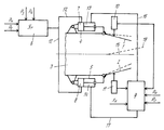
На чертеже представлена схема системы регулирования положения створок плоского выхлопного сопла газотурбинного двигателя, реализующая предложенный способ. The drawing shows a diagram of a system for regulating the position of the flaps of a flat exhaust nozzle of a gas turbine engine that implements the proposed method.
Система регулирования положения створок (панелей) 1 и 2 выхлопного сопла 3 газотурбинного двигателя включает гидроцилиндры 4 и 5, регулятор 6, связанный с полостями 7 и 8, обеспечивающими закрытие створок сопла, регулятор 9 положения створок сопла и датчики 10 и 11 положения створок. The system for regulating the position of the shutters (panels) 1 and 2 of the
Предложенный способ регулирования положения створок выхлопного сопла газотурбинного двигателя реализуется следующим образом. The proposed method for regulating the position of the shutters of the exhaust nozzle of a gas turbine engine is implemented as follows.
К регулятору 6 поступают сигналы, пропорциональные давлению газа перед турбиной Р3 и пропорциональные давлению газа за турбиной Р4. Кроме того, регулятор 6 связан с гидравлическим источником высокого давления по магистрали Рн и низкого (сливного) давления по магистрали Рс. Регулятор 6 (в данном случае Пт) сравнивает сигналы Р3 и Р4 и при увеличении их разницы от заданной величины по трубопроводам 12 увеличивает давление в полостях 7 и 8 гидроцилиндров 4 и 5, которые перемещают створки 1 и 2 на прикрытие сопла 3 и тем самым уменьшают перепад давления газа на турбине ГТД. Давление в полостях 4 и 5 при этом поддерживают постоянным.The
Раскрытие створок происходит за счет усилия, образующегося от действия давления выхлопного газа на створки 1 и 2 сопла и давления жидкости, действующего в полостях 13 и 14 гидроцилиндров, обеспечивающих открытие сопла. The opening of the valves occurs due to the force generated by the pressure of the exhaust gas on the
Для поддержания осесимметричного положения створок 1 и 2 при изменении их положения относительно продольной оси 15 двигателя на последнем предусмотрены датчики 10 и 11 положения створок. Сигналы с датчиков поступают на регулятор 9 положения створок сопла, сравниваются между собой и при их отклонении от заданной величины повышается давление в полости 13 гидроцилиндра 4 и уменьшается в полости 14 гидроцилиндра 5, если створка 1 отклонилась от оси 15 двигателя в сторону прикрытия сопла, а створка 2 в сторону открытия. To maintain the axisymmetric position of the
При изменении положения створок 1 и 2 в противоположном направлении соответственно повышают давление в полости 14 и уменьшают в полости 13, в некоторых случаях достаточно повысить или понизить давление только в одной из полостей 13 или 14 гидроцилиндров 4 и 5. Изменение давлений в этих полостях производится регулятором 9 положения створок по трубопроводам 16 и 17. Регулятор 9 как и регулятор 6 связан с источником высокого давления по трубопроводам Рн и Рс (нагнетания и слива).When changing the position of the
Регулятор 9 положения створок не только поддерживает их симметричное положение относительно продольной оси 15 двигателя, но и может отклонить вектор тяги относительно оси 15. Для этого в регулятор 9 подают командный сигнал Хк и в зависимости от его величины и знака изменяют давление в полостях 13 и 14, поворачивая створки 1 и 2 вверх или вниз на заданный угол. После этого регулятор 9 поддерживает осесимметричное положение створок относительно оси 18 вектора тяги.The
При реализации предложенного способа регулятор 6 может поддерживать любой внутридвигательный параметр, который зависит от площади сечения сопла, а не только от Пт, а для перемещения створок может использоваться не один гидроцилиндр, а несколько.When implementing the proposed method, the
Claims (1)
Priority Applications (1)
| Application Number | Priority Date | Filing Date | Title |
|---|---|---|---|
| RU92015529A RU2038503C1 (en) | 1992-12-30 | 1992-12-30 | Method of controlling position of exhaust nozzle valves of gas-turbine engine |
Applications Claiming Priority (1)
| Application Number | Priority Date | Filing Date | Title |
|---|---|---|---|
| RU92015529A RU2038503C1 (en) | 1992-12-30 | 1992-12-30 | Method of controlling position of exhaust nozzle valves of gas-turbine engine |
Publications (2)
| Publication Number | Publication Date |
|---|---|
| RU92015529A RU92015529A (en) | 1995-01-27 |
| RU2038503C1 true RU2038503C1 (en) | 1995-06-27 |
Family
ID=20134825
Family Applications (1)
| Application Number | Title | Priority Date | Filing Date |
|---|---|---|---|
| RU92015529A RU2038503C1 (en) | 1992-12-30 | 1992-12-30 | Method of controlling position of exhaust nozzle valves of gas-turbine engine |
Country Status (1)
| Country | Link |
|---|---|
| RU (1) | RU2038503C1 (en) |
Cited By (5)
| Publication number | Priority date | Publication date | Assignee | Title |
|---|---|---|---|---|
| RU2188333C1 (en) * | 2001-01-19 | 2002-08-27 | Открытое акционерное общество "А.Люлька-Сатурн" | Turbojet engine |
| RU2222707C2 (en) * | 1998-07-22 | 2004-01-27 | Дженерал Электрик Компани | Method of calibration of great number of slave mechanisms connected to drive ring on control system for turning exhaust flaps in rotating nozzle and control system to regulate travel of great number of slave mechanisms distributed over circumference |
| RU2312244C1 (en) * | 2006-05-17 | 2007-12-10 | Федеральное государственное унитарное предприятие "Московское машиностроительное производственное предприятие "САЛЮТ" (ФГУП "ММПП "САЛЮТ") | Method of control of vectored-thrust nozzle of aircraft gas-turbine engine |
| RU2326258C1 (en) * | 2006-10-12 | 2008-06-10 | Федеральное государственное унитарное предприятие "Московское машиностроительное производственное предприятие "САЛЮТ" (ФГУП "ММПП "САЛЮТ") | Control system for nozzle with adjustable traction vector of aviation gas-turbine engine |
| RU2443890C1 (en) * | 2010-09-30 | 2012-02-27 | Федеральное государственное унитарное предприятие "Научно-производственный центр газотурбостроения "Салют" (ФГУП "НПЦ газотурбостроения "Салют") | Method of controlling critical section area of two-stage gas turbine engine jet nozzle |
-
1992
- 1992-12-30 RU RU92015529A patent/RU2038503C1/en active
Non-Patent Citations (2)
| Title |
|---|
| Гаевский С.А. и др. Автоматика авиационных газотурбинных силовых установок. Оборонгиз, 1980, с.180-188. * |
| Шевяков А.А. Автоматика авиационных и ракетных силовых установок. М.: Машиностроение, 1970, с.131. * |
Cited By (5)
| Publication number | Priority date | Publication date | Assignee | Title |
|---|---|---|---|---|
| RU2222707C2 (en) * | 1998-07-22 | 2004-01-27 | Дженерал Электрик Компани | Method of calibration of great number of slave mechanisms connected to drive ring on control system for turning exhaust flaps in rotating nozzle and control system to regulate travel of great number of slave mechanisms distributed over circumference |
| RU2188333C1 (en) * | 2001-01-19 | 2002-08-27 | Открытое акционерное общество "А.Люлька-Сатурн" | Turbojet engine |
| RU2312244C1 (en) * | 2006-05-17 | 2007-12-10 | Федеральное государственное унитарное предприятие "Московское машиностроительное производственное предприятие "САЛЮТ" (ФГУП "ММПП "САЛЮТ") | Method of control of vectored-thrust nozzle of aircraft gas-turbine engine |
| RU2326258C1 (en) * | 2006-10-12 | 2008-06-10 | Федеральное государственное унитарное предприятие "Московское машиностроительное производственное предприятие "САЛЮТ" (ФГУП "ММПП "САЛЮТ") | Control system for nozzle with adjustable traction vector of aviation gas-turbine engine |
| RU2443890C1 (en) * | 2010-09-30 | 2012-02-27 | Федеральное государственное унитарное предприятие "Научно-производственный центр газотурбостроения "Салют" (ФГУП "НПЦ газотурбостроения "Салют") | Method of controlling critical section area of two-stage gas turbine engine jet nozzle |
Similar Documents
| Publication | Publication Date | Title |
|---|---|---|
| EP0977937B1 (en) | Internal combustion engine with an exhaust gas turbocharger | |
| DE3032402C2 (en) | ||
| US4292805A (en) | Servo-valve convertible construction | |
| DE2823067A1 (en) | RELIEF CONTROL FOR A TURBOCHARGER | |
| EP0802311A3 (en) | Fuel flow control valve | |
| RU2038503C1 (en) | Method of controlling position of exhaust nozzle valves of gas-turbine engine | |
| GB2285285A (en) | Fuel staging system | |
| GB1274418A (en) | A fuel nozzle for a gas tubine engine | |
| EP3455477A1 (en) | Turbine for an exhaust turbocharger having a two-volute turbine housing and a linear valve for volute connection and wastegate control | |
| EP1355052A1 (en) | Charge system for an internal combustion engine and process for its control | |
| DE2617709C3 (en) | Turbocharged internal combustion engine with compression ignition | |
| EP0123990B1 (en) | Control device for a pressure-wave charger | |
| DE3040139A1 (en) | CONTROL SYSTEM FOR A GAS TURBINE | |
| DE19812843B4 (en) | Method for boost pressure control of an internal combustion engine | |
| DE2132334A1 (en) | Control device for a transformation engine | |
| KR900700740A (en) | Method and system for adjusting lambda value of air / fuel mixture | |
| DE2819876A1 (en) | FLOW REGULATOR | |
| EP1225330B1 (en) | Apparatus for controlling a spark ignited combustion engine | |
| DE19901721A1 (en) | Discharge pressure control procedure for screw compressor used to compress fuel gas supplied to gas turbine | |
| DE4204019A1 (en) | CONTROLLED EXHAUST TURBOCHARGER TURBINE FOR AN INTERNAL COMBUSTION ENGINE | |
| DE19505915A1 (en) | Air mass controller for a turbocharged internal combustion engine with an adapted I component | |
| SU658301A1 (en) | System of regulating steam turbine runner rpm | |
| RU92015529A (en) | METHOD OF REGULATING THE POSITION OF THE RODS OF THE EXHAUST DOWN OF A GAS TURBINE ENGINE | |
| JPS562497A (en) | Blade controller for movable-blade pump | |
| KR100252360B1 (en) | Actuator structure of turbo engine |