RU2036527C1 - Fuse - Google Patents
Fuse Download PDFInfo
- Publication number
- RU2036527C1 RU2036527C1 SU904831816A SU4831816A RU2036527C1 RU 2036527 C1 RU2036527 C1 RU 2036527C1 SU 904831816 A SU904831816 A SU 904831816A SU 4831816 A SU4831816 A SU 4831816A RU 2036527 C1 RU2036527 C1 RU 2036527C1
- Authority
- RU
- Russia
- Prior art keywords
- housing
- fuse
- fuse according
- conductor
- conductors
- Prior art date
Links
Images
Classifications
-
- H—ELECTRICITY
- H01—ELECTRIC ELEMENTS
- H01H—ELECTRIC SWITCHES; RELAYS; SELECTORS; EMERGENCY PROTECTIVE DEVICES
- H01H85/00—Protective devices in which the current flows through a part of fusible material and this current is interrupted by displacement of the fusible material when this current becomes excessive
- H01H85/02—Details
- H01H85/04—Fuses, i.e. expendable parts of the protective device, e.g. cartridges
- H01H85/05—Component parts thereof
- H01H85/18—Casing fillings, e.g. powder
- H01H85/185—Insulating members for supporting fusible elements inside a casing, e.g. for helically wound fusible elements
-
- H—ELECTRICITY
- H01—ELECTRIC ELEMENTS
- H01H—ELECTRIC SWITCHES; RELAYS; SELECTORS; EMERGENCY PROTECTIVE DEVICES
- H01H85/00—Protective devices in which the current flows through a part of fusible material and this current is interrupted by displacement of the fusible material when this current becomes excessive
- H01H85/02—Details
- H01H85/04—Fuses, i.e. expendable parts of the protective device, e.g. cartridges
- H01H85/041—Fuses, i.e. expendable parts of the protective device, e.g. cartridges characterised by the type
- H01H85/0411—Miniature fuses
-
- H—ELECTRICITY
- H01—ELECTRIC ELEMENTS
- H01H—ELECTRIC SWITCHES; RELAYS; SELECTORS; EMERGENCY PROTECTIVE DEVICES
- H01H85/00—Protective devices in which the current flows through a part of fusible material and this current is interrupted by displacement of the fusible material when this current becomes excessive
- H01H85/02—Details
- H01H85/04—Fuses, i.e. expendable parts of the protective device, e.g. cartridges
- H01H85/041—Fuses, i.e. expendable parts of the protective device, e.g. cartridges characterised by the type
- H01H85/048—Fuse resistors
-
- H—ELECTRICITY
- H01—ELECTRIC ELEMENTS
- H01H—ELECTRIC SWITCHES; RELAYS; SELECTORS; EMERGENCY PROTECTIVE DEVICES
- H01H85/00—Protective devices in which the current flows through a part of fusible material and this current is interrupted by displacement of the fusible material when this current becomes excessive
- H01H85/0039—Means for influencing the rupture process of the fusible element
- H01H85/0047—Heating means
- H01H85/0052—Fusible element and series heating means or series heat dams
Abstract
Description
Изобретение относится к электротехнике, а именно к плавким предохранителям. The invention relates to electrical engineering, namely to fuses.
Известный плавкий предохранитель, содержащий корпус из изоляционного материала с контактными выводами и плавкий элемент, расположенный внутри корпуса [1]
Недостатком указанного предохранителя является то, что он не способен подавлять кратковременно возникающие при электропитании переходные составляющие тока и достаточно быстро реагировать на перегрев схемы с целью ее защиты от повреждения в результате нагрева. Нежелательные переходные составляющие тока предотвращаются по этой причине в обычных электронных схемах с помощью дискретных добавочных сопротивлений, а для защиты схем и/или устройств от перегрева используются отдельные тепловые предохранители.Known fuse comprising a housing of insulating material with contact leads and a fuse located inside the housing [1]
The disadvantage of this fuse is that it is not able to suppress transient current components that briefly occur during power supply and respond quickly enough to overheating of the circuit in order to protect it from damage due to heating. Unwanted transient current components are prevented for this reason in conventional electronic circuits by using discrete additional resistances, and separate thermal fuses are used to protect the circuits and / or devices from overheating.
Целью изобретения является повышение надежности срабатывания. The aim of the invention is to increase the reliability of operation.
Указанная цель достигается благодаря тому, что в указанном плавком предохранителе корпус состоит из трех частей, две крайние из которых идентичны, плавкий предохранитель снабжен двумя соединительными проводниками, каждый из которых расположен между плавким элементом и контактным выводом на внешней крайней части корпуса, средняя часть корпуса снабжена несколькими поперечными стенками различной высоты с отверстиями, плавкий элемент расположен в средней части корпуса и пропущен через указанные отверстия. This goal is achieved due to the fact that in the specified fuse the housing consists of three parts, the two extremes of which are identical, the fuse is equipped with two connecting conductors, each of which is located between the fuse element and the contact terminal on the outer extreme part of the housing, the middle part of the housing is provided several transverse walls of various heights with holes, the fusible element is located in the middle of the body and passed through these holes.
Кроме того, в плавком предохранителе каждая внешняя крайняя часть корпуса может иметь уплощение, предназначенное для электрического соединения плавкого проводника и соединительного проводника, а в качестве соединительных проводников могут быть использованы резисторы. Кроме того, в плавком предохранителе центральная часть корпуса может быть снабжена окантовкой, внутри которой расположены указанные поперечные стенки. In addition, in the fuse, each outermost part of the housing may have a flattening designed to electrically connect the fusible conductor and the connecting conductor, and resistors may be used as connecting conductors. In addition, in the fuse, the central part of the housing may be provided with a fringing, inside which are located the transverse walls.
В плавком предохранителе крайние части корпуса могут быть выполнены с винтовой поверхностью, а средняя поперечная стенка может быть выполнена с большей толщиной, чем крайние. In the fuse, the extreme parts of the body can be made with a helical surface, and the middle transverse wall can be made with a larger thickness than the extreme.
Кроме того, корпус плавкого предохранителя может быть снабжен оболочкой, имеющей форму трубы, а контактные выводы могут представлять собой залитые в корпус плавкого предохранителя проводники или контактные наконечники. In addition, the fuse housing may be provided with a shell having the shape of a pipe, and the contact leads may be conductors or contact lugs embedded in the fuse housing.
И наконец в предохранителе плавкий элемент может состоять из эвтектического сплава свинца и висмута с температурой плавления около 125оС или иметь прямоугольное поперечное сечение.Finally the fuse element in the fuse may consist of a eutectic alloy of lead and bismuth having a melting point of about 125 ° C or have a rectangular cross section.
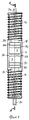
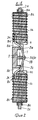
На фиг. 1 изображен корпус плавкого предохранителя сверху без вложенных плавких или резистивных проводников; на фиг.2 корпус плавкого предохранителя в продольном сечении вдоль линии А-А, причем плавкий проводник вложен, а резистивные проводники обозначены. In FIG. 1 shows a fuse housing on top without embedded fuses or resistors; figure 2, the fuse body in longitudinal section along the line aa, and the fuse is embedded, and the resistive conductors are indicated.
Корпус 1 плавкого предохранителя охватывают в основном три области 1а, 1в и 1с и он состоит в предпочтительном случае из пластмассы или керамики. The fuse housing 1 mainly covers three
Области 1а и 1с корпуса могут быть взаимно идентично и зеркально относительно оси симметрии соединены с центральной областью 1в корпуса. Они укомплектованы каждая в предпочтительном случае одним присоединительным проводником 2а и 2с, которые могут служить для впаивания плавкого предохранителя, например, в печатную схему. Благоприятным является случай, когда обе боковых области 1а и 1с корпуса имеют в основном круглое поперечное сечение и имеют форму, схожую с формой винта. В позиции перехода и в среднюю область 1в обе внешних области 1а и 1с корпуса содержат каждая по одному уплощению 3а и 3с, функция которых описана ниже. Region 1A and 1C of the housing can be mutually identical and mirrored relative to the axis of symmetry connected to the Central region 1B of the housing. They are each preferably equipped with one connecting
Центральная область 1в корпуса имеет в случае ее рассмотрения сверху прямоугольную форму и содержит окантовку 4, внутри которой расположен центральный блок 5 с тремя поперечными стенками 5а, 5в и 5с. Средняя поперечная стенка 5в имеет при этом большую высоту по сравнению с обеими другими поперечными стенками 5а и 5с, к которым примыкает по одному отверстию 6а или 6с. Внешние области центральной поперечной стенки 5в вытянуты до высоты окантовки 4 и служат в качестве боковых ограничений или упоров для плавкого проводника 7. When viewed from above, the
Плавкий проводник 7, (речь идет предпочтительно о плоском проводнике из эвтектического сплава свинца и висмута с точкой плавления около 125оС) проходит от уплощения 3а на боковой области 1а корпуса через отверстие 6а в средней области 1в корпуса через три поперечных стенки 5а, 5в и 5с и через отверстие 6с к уплощению 3с на боковой области 1с корпуса. На обоих уплощениях 3а и 3с он находится в электрическом контакте со вложенными в имеющие винтовую форму бороздки боковых областей 1а и 1с корпуса резистивными проводниками 8а и 8с, которые в свою очередь также соединены с теми или иными контактными проводниками 2а или 2с таким образом, что они обвиты вокруг них. За счет этого возникает электрическое соединение между присоединительным проводником 2а и присоединительным проводником 2с, которое проходит через резистивный проводник 8а, плавкий проводник 7 и резистивный проводник 8с. С целью повышения надежности контакта контактные зоны присоединительного проводника 2а (резистивного проводника 8а, резистивного проводника 8а, плавкого проводника 7, а также плавкого проводника 7, резистивного проводника 8с и резистивного проводника 8с) присоединительного проводника 2с могут покрывать электропроводящим клеем, например, содержащим медь или серебро двухкомпонентным клеем. На основании низкой температуры плавления плавкого проводника 7 спаивание его с резистивными проводниками 8а и 8с является весьма затруднительной и едва ли рациональной операцией, однако при соответствующем выборе припоя эта возможность не исключается. Три области 1а, 1в и 1с корпуса плавкого предохранителя во избежание механических повреждений плавкого проводника и резистивных проводников размещаются предпочтительно в пластмассовой трубке по возможности в форме усадочного шланга таким образом, что возникает конструктивный элемент, который как по внешнему виду, так и по размеру в основном соответствует сопротивлению.Fusible conductor 7, (it is preferably of a flat conductor of the eutectic alloy of lead and bismuth having a melting point of about 125 C) extends from flattening 3a on the
Размещение плавкого проводника между двумя обмотками резистивного проводника, из которых каждая служит в качестве добавочного сопротивления, является предпочтительным и обеспечивает нечувствительность плавкого предохранителя к воздействию переходных составляющих тока, так как последние могут в основном исключаться лишь с помощью того или иного добавочного сопротивления. Использование плоского, в основном имеющего прямоугольное поперечное сечение плавкого проводника, поддерживает при этом эффект добавочного сопротивления. Placing a fusible conductor between two windings of the resistive conductor, each of which serves as an additional resistance, is preferable and ensures that the fuse is insensitive to the effects of transient current components, since the latter can mainly be eliminated only with the help of one or another additional resistance. The use of a flat, mainly having a rectangular cross-section of the fusible conductor, while supporting the effect of additional resistance.
Использование плавкого проводника с температурой плавления лишь около 125оС также является предпочтительным и может быть реализовано в практических условиях лишь благодаря соединению плавкого проводника с добавочными сопротивлениями из резистивного проводника на корпусе предохранителя. При этом следует учитывать, то, что при необходимости можно отказаться от использования обмоток из резистивного проводника и применять вместо них низкоомные соединительные проводники, которые могут обеспечивать электрическое соединение между плавким проводником и присоединительными проводниками. С помощью этих проводников или резистивных проводников обеспечивается достаточная термическая изоляция плавкого проводника 7 относительно присоединительных проводников, а именно таким образом, что они могут без проблем впаиваться, например, в печатную схему без опасности того, что в результате этого расплавится плавкий проводник. С другой стороны, низкая точка плавления эвтектического сплава свинца и висмута позволяет также использовать плавкий предохранитель в качестве теплового предохранителя, который плавится до того, как перегрев в области схемы, в которой расположен плавкий предохранитель, приведет к повреждению этой схемы.Using a fusible conductor with a melting point of only about 125 ° C is also preferred and may be implemented in practical terms only by the connection of the fusible conductor with a series resistor of a resistive conductor on the body of the fuse. It should be borne in mind that, if necessary, you can refuse to use windings from a resistive conductor and use low-resistance connecting conductors instead, which can provide an electrical connection between the fusible conductor and the connecting conductors. Using these conductors or resistive conductors, sufficient thermal insulation of the fusible conductor 7 with respect to the connecting conductors is ensured, namely, in such a way that they can be soldered without problems, for example, into a printed circuit without the risk that the fuse will melt as a result. On the other hand, the low melting point of the eutectic alloy of lead and bismuth also allows the use of a fuse as a thermal fuse, which melts before overheating in the area of the circuit in which the fuse is located will damage this circuit.
Кроме того, форма центрального блока 5 с его тремя поперечными стенками 5а, 5в и 5с создает большие преимущества по сравнению с обычными плавкими предохранителями, так как ни в одном из положений плавкого предохранителя перегоревший и оплавленный плавкий проводник не может образовать дорожку из расплава, которая соединила бы оба оставшихся плавких проводника. In addition, the shape of the
Предложенный плавкий предохранитель может автоматически и большими сериями изготавливаться при небольших расходах. Величина коммутационного тока может определяться на основании адекватного определения размера поперечного сечения плавкого проводника. Величина обоих добавочных сопротивлений также может без проблем регулироваться за счет соответствующего выбора резистивного проводника. The proposed fuse can be automatically and in large batches manufactured at low cost. The value of the switching current can be determined on the basis of an adequate determination of the size of the cross section of the fuse. The value of both additional resistances can also be easily adjusted due to the appropriate choice of the resistive conductor.
Само собой разумеется, что в зависимости от вида использования соответствующего изобретению плавкого предохранителя присоединительные проводники 2а и 2с могут быть заменены, например, контактными наконечниками, которые известным образом могут насаживаться на оба конца боковых областей 1а и 1с корпуса. It goes without saying that, depending on the type of use of the fuse according to the invention, the connecting
Плавкий предохранитель обеспечивает по сравнению с известными элементами такого рода существенные преимущества, которые заключаются, в частности, в том, что один единственный, имеющий малые размеры, дискретный элемент может выполнять несколько функций. A fuse provides significant advantages over known elements of this kind, which include, in particular, the fact that a single, discrete element can have several functions.
Claims (10)
Applications Claiming Priority (3)
| Application Number | Priority Date | Filing Date | Title |
|---|---|---|---|
| CH1003/89 | 1989-03-17 | ||
| CH1003/89A CH677419A5 (en) | 1989-03-17 | 1989-03-17 | |
| PCT/CH1990/000071 WO1990011608A1 (en) | 1989-03-17 | 1990-03-15 | Fuse |
Publications (1)
| Publication Number | Publication Date |
|---|---|
| RU2036527C1 true RU2036527C1 (en) | 1995-05-27 |
Family
ID=4200186
Family Applications (1)
| Application Number | Title | Priority Date | Filing Date |
|---|---|---|---|
| SU904831816A RU2036527C1 (en) | 1989-03-17 | 1990-11-15 | Fuse |
Country Status (16)
| Country | Link |
|---|---|
| EP (1) | EP0417223B1 (en) |
| JP (1) | JPH03504783A (en) |
| KR (1) | KR920700464A (en) |
| AT (1) | ATE116478T1 (en) |
| AU (1) | AU640917B2 (en) |
| BR (1) | BR9005961A (en) |
| CA (1) | CA2028862A1 (en) |
| CH (1) | CH677419A5 (en) |
| DE (1) | DE59008120D1 (en) |
| DK (1) | DK0417223T3 (en) |
| ES (1) | ES2070316T3 (en) |
| FI (1) | FI905680A0 (en) |
| HU (2) | HUT56660A (en) |
| NO (1) | NO904973L (en) |
| RU (1) | RU2036527C1 (en) |
| WO (1) | WO1990011608A1 (en) |
Families Citing this family (3)
| Publication number | Priority date | Publication date | Assignee | Title |
|---|---|---|---|---|
| US5418516A (en) * | 1993-11-09 | 1995-05-23 | Littlefuse, Inc. | Surge resistor fuse |
| US6552646B1 (en) * | 2000-04-10 | 2003-04-22 | Bel-Fuse, Inc. | Capless fuse |
| US10992254B2 (en) | 2014-09-09 | 2021-04-27 | Shoals Technologies Group, Llc | Lead assembly for connecting solar panel arrays to inverter |
Family Cites Families (7)
| Publication number | Priority date | Publication date | Assignee | Title |
|---|---|---|---|---|
| DE312052C (en) * | ||||
| GB191402301A (en) * | 1914-01-28 | 1914-11-12 | Herbert Henry Berry | Improvements in Electric Safety Fuses. |
| US1501018A (en) * | 1919-07-08 | 1924-07-08 | Gen Electric | Electric-circuit protective device |
| US2017492A (en) * | 1934-03-24 | 1935-10-15 | John B Glowacki | Cartridge ferrule type refillable fuse and element |
| US3793560A (en) * | 1973-06-18 | 1974-02-19 | J Schultheis | Resistive thermal protective device for inductances |
| GB2096844A (en) * | 1981-04-10 | 1982-10-20 | Beswick Kenneth E Ltd | Electrical fuse |
| GB2182811B (en) * | 1985-11-08 | 1990-09-19 | Cooper Ind Inc | Time lag electrical fuse |
-
1989
- 1989-03-17 CH CH1003/89A patent/CH677419A5/de not_active IP Right Cessation
-
1990
- 1990-03-15 HU HU902187A patent/HUT56660A/en unknown
- 1990-03-15 EP EP90903752A patent/EP0417223B1/en not_active Expired - Lifetime
- 1990-03-15 HU HU902187A patent/HU208194B/en not_active IP Right Cessation
- 1990-03-15 KR KR1019900702442A patent/KR920700464A/en not_active Application Discontinuation
- 1990-03-15 DK DK90903752.5T patent/DK0417223T3/en not_active Application Discontinuation
- 1990-03-15 AT AT90903752T patent/ATE116478T1/en active
- 1990-03-15 CA CA002028862A patent/CA2028862A1/en not_active Abandoned
- 1990-03-15 DE DE59008120T patent/DE59008120D1/en not_active Expired - Fee Related
- 1990-03-15 AU AU51750/90A patent/AU640917B2/en not_active Ceased
- 1990-03-15 BR BR909005961A patent/BR9005961A/en unknown
- 1990-03-15 ES ES90903752T patent/ES2070316T3/en not_active Expired - Lifetime
- 1990-03-15 WO PCT/CH1990/000071 patent/WO1990011608A1/en active IP Right Grant
- 1990-03-15 JP JP2503870A patent/JPH03504783A/en active Pending
- 1990-11-15 RU SU904831816A patent/RU2036527C1/en active
- 1990-11-16 FI FI905680A patent/FI905680A0/en not_active IP Right Cessation
- 1990-11-16 NO NO90904973A patent/NO904973L/en unknown
Non-Patent Citations (1)
| Title |
|---|
| Кузнецов Р.С. Аппараты распределения электрической энергии на напряжение до 1000 В, М.:, Энергия, 1970, с.332 - 334, 359,360. * |
Also Published As
| Publication number | Publication date |
|---|---|
| HU902187D0 (en) | 1991-08-28 |
| EP0417223B1 (en) | 1994-12-28 |
| HUT56660A (en) | 1991-09-30 |
| WO1990011608A1 (en) | 1990-10-04 |
| FI905680A0 (en) | 1990-11-16 |
| DK0417223T3 (en) | 1995-04-03 |
| NO904973D0 (en) | 1990-11-16 |
| CA2028862A1 (en) | 1990-09-18 |
| ES2070316T3 (en) | 1995-06-01 |
| HU208194B (en) | 1993-08-30 |
| EP0417223A1 (en) | 1991-03-20 |
| AU640917B2 (en) | 1993-09-09 |
| KR920700464A (en) | 1992-02-19 |
| NO904973L (en) | 1990-11-16 |
| ATE116478T1 (en) | 1995-01-15 |
| AU5175090A (en) | 1990-10-22 |
| JPH03504783A (en) | 1991-10-17 |
| CH677419A5 (en) | 1991-05-15 |
| DE59008120D1 (en) | 1995-02-09 |
| BR9005961A (en) | 1991-08-06 |
Similar Documents
| Publication | Publication Date | Title |
|---|---|---|
| US6269745B1 (en) | Electrical fuse | |
| CA2371101C (en) | Miniature fuse of surface-mount type | |
| EP0270954B1 (en) | Chip-type fuse | |
| US4533896A (en) | Fuse for thick film device | |
| US6304166B1 (en) | Low profile mount for metal oxide varistor package and method | |
| US6664886B2 (en) | Fuse with fuse link coating | |
| JPH0627959Y2 (en) | diode | |
| JPH05198246A (en) | Thermal fuse and protective circuit device | |
| GB2096844A (en) | Electrical fuse | |
| US2966649A (en) | Fuse resistor | |
| CA2159188A1 (en) | An electric fuse and protective circuit | |
| RU2036527C1 (en) | Fuse | |
| US5418516A (en) | Surge resistor fuse | |
| WO1998025285A2 (en) | Electrical fuse | |
| CA1140963A (en) | Miniature electric fuse | |
| JPH0478104A (en) | Excess current protective component | |
| JPH0638351Y2 (en) | Temperature fuse | |
| CA1191178A (en) | Fuse for thick film device | |
| JPH03109715A (en) | Solid electrolytic capacitor in chip structure | |
| JPH03105825A (en) | Small size time-lag fuse | |
| JPH09147710A (en) | Resistive temperature fuse | |
| JPH0513205A (en) | Overcurrent and overvoltage protective element | |
| JPH04365304A (en) | Chip resistor fitted with fuse | |
| JPS61110419A (en) | Solid electrolytic capacitor with fuse | |
| JPH02119214A (en) | Fuse-incorporated type solid electrolytic capacitor |