RU2031314C1 - Device for regulating flow for gas-release contrivance and method of making filter for application in the device for regulating fuel flow - Google Patents
Device for regulating flow for gas-release contrivance and method of making filter for application in the device for regulating fuel flow Download PDFInfo
- Publication number
- RU2031314C1 RU2031314C1 SU914895564A SU4895564A RU2031314C1 RU 2031314 C1 RU2031314 C1 RU 2031314C1 SU 914895564 A SU914895564 A SU 914895564A SU 4895564 A SU4895564 A SU 4895564A RU 2031314 C1 RU2031314 C1 RU 2031314C1
- Authority
- RU
- Russia
- Prior art keywords
- filter
- microcells
- gas
- fuel
- disk
- Prior art date
Links
Images


Classifications
-
- F—MECHANICAL ENGINEERING; LIGHTING; HEATING; WEAPONS; BLASTING
- F23—COMBUSTION APPARATUS; COMBUSTION PROCESSES
- F23Q—IGNITION; EXTINGUISHING-DEVICES
- F23Q2/00—Lighters containing fuel, e.g. for cigarettes
- F23Q2/16—Lighters with gaseous fuel, e.g. the gas being stored in liquid phase
-
- G—PHYSICS
- G05—CONTROLLING; REGULATING
- G05D—SYSTEMS FOR CONTROLLING OR REGULATING NON-ELECTRIC VARIABLES
- G05D7/00—Control of flow
- G05D7/01—Control of flow without auxiliary power
-
- F—MECHANICAL ENGINEERING; LIGHTING; HEATING; WEAPONS; BLASTING
- F23—COMBUSTION APPARATUS; COMBUSTION PROCESSES
- F23Q—IGNITION; EXTINGUISHING-DEVICES
- F23Q2/00—Lighters containing fuel, e.g. for cigarettes
- F23Q2/16—Lighters with gaseous fuel, e.g. the gas being stored in liquid phase
- F23Q2/162—Lighters with gaseous fuel, e.g. the gas being stored in liquid phase with non-adjustable gas flame
- F23Q2/163—Burners (gas valves)
-
- Y—GENERAL TAGGING OF NEW TECHNOLOGICAL DEVELOPMENTS; GENERAL TAGGING OF CROSS-SECTIONAL TECHNOLOGIES SPANNING OVER SEVERAL SECTIONS OF THE IPC; TECHNICAL SUBJECTS COVERED BY FORMER USPC CROSS-REFERENCE ART COLLECTIONS [XRACs] AND DIGESTS
- Y10—TECHNICAL SUBJECTS COVERED BY FORMER USPC
- Y10S—TECHNICAL SUBJECTS COVERED BY FORMER USPC CROSS-REFERENCE ART COLLECTIONS [XRACs] AND DIGESTS
- Y10S264/00—Plastic and nonmetallic article shaping or treating: processes
- Y10S264/13—Cell size and distribution control while molding a foam
-
- Y—GENERAL TAGGING OF NEW TECHNOLOGICAL DEVELOPMENTS; GENERAL TAGGING OF CROSS-SECTIONAL TECHNOLOGIES SPANNING OVER SEVERAL SECTIONS OF THE IPC; TECHNICAL SUBJECTS COVERED BY FORMER USPC CROSS-REFERENCE ART COLLECTIONS [XRACs] AND DIGESTS
- Y10—TECHNICAL SUBJECTS COVERED BY FORMER USPC
- Y10S—TECHNICAL SUBJECTS COVERED BY FORMER USPC CROSS-REFERENCE ART COLLECTIONS [XRACs] AND DIGESTS
- Y10S264/00—Plastic and nonmetallic article shaping or treating: processes
- Y10S264/48—Processes of making filters
-
- Y—GENERAL TAGGING OF NEW TECHNOLOGICAL DEVELOPMENTS; GENERAL TAGGING OF CROSS-SECTIONAL TECHNOLOGIES SPANNING OVER SEVERAL SECTIONS OF THE IPC; TECHNICAL SUBJECTS COVERED BY FORMER USPC CROSS-REFERENCE ART COLLECTIONS [XRACs] AND DIGESTS
- Y10—TECHNICAL SUBJECTS COVERED BY FORMER USPC
- Y10S—TECHNICAL SUBJECTS COVERED BY FORMER USPC CROSS-REFERENCE ART COLLECTIONS [XRACs] AND DIGESTS
- Y10S55/00—Gas separation
- Y10S55/13—Polyurethane filters
Landscapes
- Engineering & Computer Science (AREA)
- Combustion & Propulsion (AREA)
- General Engineering & Computer Science (AREA)
- Mechanical Engineering (AREA)
- Chemical & Material Sciences (AREA)
- Automation & Control Theory (AREA)
- Physics & Mathematics (AREA)
- General Physics & Mathematics (AREA)
- Lighters Containing Fuel (AREA)
- Feeding And Controlling Fuel (AREA)
- Control Of Combustion (AREA)
- Vaporization, Distillation, Condensation, Sublimation, And Cold Traps (AREA)
- Filtering Of Dispersed Particles In Gases (AREA)
- Manufacture Of Porous Articles, And Recovery And Treatment Of Waste Products (AREA)
Abstract
Description
Изобретение относится к устройствам регулирования факела для газовых сигаретных зажигалок, горелок щипцов для завивки волос и других аналогичных средств. The invention relates to torch control devices for gas cigarette lighters, curling iron burners and other similar means.
Цель изобретения состоит в создании постоянного потока газообразного топлива через клапан сопла или горелки зажигалок или других пламяобразующих средств и соответственно в устранении необходимости в элементе регулирования потока топлива, регулируемого вручную. The purpose of the invention is to create a constant flow of gaseous fuel through the valve of the nozzle or burner of lighters or other flame-forming means and, accordingly, to eliminate the need for a manually controlled fuel flow control element.
Микроячеистый полимер в листовой форме деформируется в результате теплового сжатия в специфических условиях и после этого дискообразные фильтры изготавливаются для монтажа в клапане горелки зажигалки или другого средства. Тепловое сжатие микроячеистого полимера образует замкнутые пузырьки, которые закрывают некоторые каналы, через которые может проходить газ, образуемый остающимися постоянными соединительными микроячейками. Во время функционирования зажигалки или другого средства повышение температуры сопровождается расширением ранее образованных замкнутых пузырьков, что приводит к сжатию соединительных постоянных микроячеек, через которые проходит топливо, тем самым автоматически снижая поток топлива через них. The microcellular polymer in sheet form is deformed as a result of thermal compression under specific conditions and after that, disk-shaped filters are made for mounting in the valve of a burner of a lighter or other means. The thermal contraction of the microcellular polymer forms closed bubbles that close some channels through which gas can pass, which is formed by the remaining permanent connecting microcells. During the functioning of a lighter or other means, an increase in temperature is accompanied by the expansion of previously formed closed bubbles, which leads to compression of the connecting constant microcells through which the fuel passes, thereby automatically reducing the flow of fuel through them.
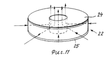
На фиг.1 приведен график, иллюстрирующий зависимость между температурой и давлением пропана, i-бутана и n-бутана; на фиг.2 - график, иллюстрирующий зависимость между температурой и высотой пламени в зажигалках, использующих предшествующие фильтры; на фиг.3 - горелки, снабженный предшествующим фильтром управления потоком, продольный разрез; на фиг.4 - клапан зажигалки, отличающийся микропористой мембраной, выполненной, в частности, из молекулярно ориентированного олефина, например полипропилена или полиэтилена, продольный разрез; на фиг.5 показаны предшествующий микропористый фильтр и покрывающий его пористый лист в сечении; на фиг.6 схематично показаны стадии способа изготовления фильтра согласно изобретению из скатанных листов микроячеистого полимера; на фиг.7 изображена часть микроячеистого полимерного фильтра перед его тепловым сжатием, в сечении; на фиг.8 - то же, часть микроячеистого полимерного фильтра после его теплового сжатия в сечении показывающем переформирование структур замкнутых воздушных пузырьков, в частности снижение количества постоянных соединенных микроячеистых образований, которые определяют каналы, через которые может проходить газообразное топливо; на фиг.9 представлен клапан горелки, отличающийся микроячеистым полимерным фильтром, продольный разрез; на фиг.10 показана та часть клапана горелки, которая поддерживает микроячеистый полимерный фильтр, показывающий схематично канал для топлива через непрерывно соединенные микроячейки; на фиг.11 изображен в перспективе микроячеистый полимерный фильтр, где показан радиально направленный внутрь канал для топлива через него; на фиг.12 - график, показывающий эффект изменения времени стадии теплового сжатия на высоту пламени при изменениях температур; на фиг.13 - график, показывающий высоту пламени при изменении температур в случае предшествующего устройства регулирования потока и в случае изобретения; на фиг.14 показана часть щипцов для завивки волос, нагретых газом, содержащих элемент регулирования потока, отличающийся микроячеистым полимерным фильтром, в сечении; на фиг. 15 - фотография микроячеистого полимерного материала при увеличении в 45 раз; на фиг.16 - фотография микроячеистого полимерного материала при увеличении в 200 раз; на фиг.17 - фотография микроячеистого полимерного материала при увеличении в 500 раз; на фиг.18 - фотография термально сжатого микроячеистого полимерного материала при увеличении в 40 раз; на фиг.19 - фотография термально сжатого микроячеистого полимерного материала при увеличении в 200 раз. Figure 1 is a graph illustrating the relationship between temperature and pressure of propane, i-butane and n-butane; figure 2 is a graph illustrating the relationship between temperature and flame height in lighters using previous filters; figure 3 - burner equipped with a preceding filter flow control, a longitudinal section; figure 4 - lighter valve, characterized by a microporous membrane made, in particular, of a molecularly oriented olefin, such as polypropylene or polyethylene, a longitudinal section; figure 5 shows the preceding microporous filter and its covering porous sheet in cross section; figure 6 schematically shows the stages of a method of manufacturing a filter according to the invention from rolled sheets of microcellular polymer; figure 7 shows a part of a microcellular polymer filter before its thermal compression, in cross section; on Fig - the same part of the microcellular polymer filter after its thermal compression in cross section showing the reformation of the structures of closed air bubbles, in particular a decrease in the number of permanent connected microcellular formations that define the channels through which gaseous fuel can pass; figure 9 presents the valve of the burner, characterized by a microcellular polymer filter, a longitudinal section; figure 10 shows that part of the burner valve that supports a microcellular polymer filter, showing schematically a channel for fuel through continuously connected microcells; figure 11 shows a perspective microcellular polymer filter, which shows a radially directed inward channel for fuel through it; Fig. 12 is a graph showing the effect of a change in time of a thermal compression stage on a flame height with temperature changes; Fig.13 is a graph showing the height of the flame when the temperature changes in the case of the previous flow control device and in the case of the invention; on Fig shows a portion of curling irons, heated with gas, containing a flow control element, characterized by a microcellular polymer filter, in cross section; in FIG. 15 is a photograph of a microcellular polymeric material with a magnification of 45 times; in Fig.16 is a photograph of a microcellular polymer material with an increase of 200 times; on Fig is a photograph of a microcellular polymer material with a magnification of 500 times; in Fig.18 is a photograph of a thermally compressed microcellular polymer material with an increase of 40 times; in Fig.19 is a photograph of a thermally compressed microcellular polymer material with a magnification of 200 times.
Описание предпочитаемого варианта реализации изобретения. Description of a preferred embodiment of the invention.
На фиг. 1 и 2 представлены графики, иллюстрирующие зависимость между давлением и температурой газа и высотой пламени и температурой соответственно. На фиг.1 видно, что если температура в зажигалке повышается, давление газа увеличивается. На фиг.2 показана зависимость между высотой пламени и температурами в зажигалках с использованием предшествующих фильтров. Из вышеприведенного видно, что если температура топлива повышается, необходимо управлять длиной пламени, чтобы обеспечить надежность и безопасность. In FIG. Figures 1 and 2 are graphs illustrating the relationship between pressure and gas temperature and flame height and temperature, respectively. Figure 1 shows that if the temperature in the lighter rises, the gas pressure increases. Figure 2 shows the relationship between flame height and temperature in lighters using previous filters. From the above it is seen that if the temperature of the fuel rises, it is necessary to control the flame length to ensure reliability and safety.
В конструкции клапана горелки по фиг.3 сжиженный газ из резервуара 1 проходит вверх через пористый полиэтиленовый фильтр 2 и газифицируется на его верхнем конце. Газообразное топливо затем проходит через дискообразный фильтр 3, который покоится на гнездообразном держателе 4. Операционная ручка образована на зажигалке или другом средстве, так что, когда пользователь активизирует ее, сопло 5 перемещается вверх под действием пружины, удаляя прокладку 6 из контакта с гнездом 7, давая возможность газифицированному топливу входить в сопло 5 через канал 8. Регулирующий рычаг (не показан) может использоваться для поворачивания наружного подвижного клапанного элемента 9, чтобы создать большее или меньшее давление на фильтр 3, для управления количеством газа, проходящего через сопло. В результате этого высота пламени может управляться вручную путем сжатия и освобождения фильтра 3. In the design of the burner valve of FIG. 3, liquefied gas from the
В конструкции (фиг.4 и 5) микропористая мембрана 10, которая в ней используется, может быть, например, типа, который описан в аналоге [1]. Она состоит из молекулярно ориентированного олефина, в частности полипропилена или полиэтилена, и имеет поры 11 радиусом 20-500 ![]()
![]()
Как видно на фиг.4, подвижный сопловый элемент 14 снабжен герметизирующей прокладкой 15, нормально смещенной в закрытое положение по отношению к гнезду 16 пружиной 17. Таким образом, когда клапанный элемент 14 поднимается, прокладка 15 перемещается в сторону от гнезда 16, и газ поступает в канал 18, направляясь наружу через верхнюю часть соплового элемента 14. As can be seen in FIG. 4, the
Материал фильтра согласно изобретению является микроячеистым полимером в форме вспененного фильтра, выполненного из полиуретана простого эфира, имеющего ячейки (пузырьки) 10-300 мкм в диаметре и плотность 0,1-0,6 г/см3. Такой микроячеистый полимерный листовой материал может быть подготовлен, например, в соответствии с прототипом [2].The filter material according to the invention is a microcellular polymer in the form of a foamed filter made of ether polyurethane having cells (bubbles) of 10-300 μm in diameter and a density of 0.1-0.6 g / cm 3 . Such a microcellular polymer sheet material can be prepared, for example, in accordance with the prototype [2].
На фиг. 6 схематично показан способ изготовления фильтров из скатанных листов 19 микроячеистого полимерного материала, такого как Порон Н-48. Скатанные листы 19 сначала разрезаются на части 20 требуемого размера. После этого каждая часть деформируется в вертикальном направлении путем теплового сжатия примерно при 180оС в течение примерно 5 мин. Это тепловое сжатие уменьшает толщину фильтрующего материала до степени, необходимой для достижения цели изобретения. Толщина каждой части 20 фильтрующего материала может быть уменьшена, например, от 2 до 1,5 мм. Термально сжатая фильтрующая часть 20 после этого разрезается для образования части 21 и в конечном счете штампуется для образования фильтрующего элемента 22, который после этого монтируется в клапане зажигалки или другом средстве. Первоначальная длина пламени, устанавливаемая на заводе, регулируется путем вращения резьбового элемента 23 (фиг.9) во время сборки.In FIG. 6 schematically shows a method for manufacturing filters from rolled
На фиг.7-8 показан микроячеистый полимерный материал до и после теплового сжатия. Как видно на фиг.7 микроячеистый полимерный листовой участок 20 имеет верхний и нижний слои 24 и 25 соответственно, которые по существу газонепроницаемые. Ряды непрерывно соединенных микроячеек 26, 27 и 28 образуют проходные каналы, через которые может проходить газовое топливо. 7-8 shows microcellular polymer material before and after thermal compression. As can be seen in FIG. 7, the microcellular
После теплового сжатия конфигурации пузырьков реформируются, как показано на фиг.8. Тепловое сжатие перегруппирует микроячейки 27, преобразуя их в независимые (замкнутые) или не соединенные друг с другом пузырьки. Результатом является снижение количества соединенных непрерывно микроячеек и тем самым снижение количества топлива, которое может проходить через них. After thermal compression, the bubble configurations are reformed as shown in FIG. Thermal compression regroups the
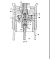
Клапан горелки, в котором используется микроячеистый полимерный фильтр 22 согласно изобретению, показан на фиг.9-11. Конструкция и функционирование клапана горелки очень похожи на показанные на фиг.3. Клапан состоит из резьбового элемента 23, в котором смонтирован подвижный сопловой элемент 29, нормально смещенный в закрытое положение пружиной 30. Подвижный сопловой элемент имеет центральный сквозной канал 31. Прокладка 32 нормально смещена вниз под действием пружины 30 в контакт с клапанным гнездом 33 элемента 34 клапанного гнезда. Микроячеистый полимерный фильтр 22 расположен на удерживающем элементе 35. A burner valve using a
Когда сопло 29 поднимается во время функционирования, прокладка 32 перемещается вверх в сторону от клапанного гнезда 33, и после этого сжиженный газ перемещается вверх по фитилю 36, а затем газифицируется на его верхнем конце. Газообразное топлива перемещается вверх вдоль внутренних стенок 37 и поворачивает радиально внутрь, проходя горизонтально через фильтр 22, как видно на фиг.10-11. После этого газообразное топливо движется вверх по центральному каналу 31 и выходит через наконечник сопла 29. When the
На фиг.10 показано прохождение газообразного топлива через разные конфигурации микроячеек 26, 28 в фильтре 22. Видно, что газообразное топливо проходит радиально внутрь через соединенные непрерывно микроячейки 26 и 28 и после этого идет вверх в канал 31 в сопле 29. Когда температура на фильтре 22 повышается, газ, захваченный в замкнутых пузырьках 27, расширяется, побуждая независимые воздушные пузырьки 27 расширяться и давить и тем самым уменьшать размер непрерывных микроячеек 26 и 28, таким образом уменьшая количество газа, способного проходить через них. Figure 10 shows the passage of gaseous fuel through different configurations of
Из вышесказанного видно, что количество прохождения газа зависит от относительных объемных отношений непрерывных, т.е. соединенных между собой, и независимых, т.е. не соединенных между собой, пузырьков 26, 28 и 27 соответственно. Это явление не присутствует в фильтрах из традиционного пеноуретана, где тонкие стенки отделяют пузырьковые образования, и тепловое сжатие не происходит, поэтому образуются комбинации непрерывных микроячеек и образований замкнутых пузырьков. It can be seen from the foregoing that the amount of gas passage depends on the relative volumetric continuous ratios, i.e. interconnected, and independent, i.e. not interconnected,
С помощью микроячеистого полимерного фильтра 22 согласно изобретению, который отличается соответственно расположенными замкнутыми пузырьками и соединенными непрерывно микроячейками, можно автоматически управлять высотой пламени. Автоматическое управление потоком газообразного топлива достигается путем сжатия проходов или каналов газообразного потока при повышении температуры. Это явление устраняет необходимость в отдельном регулирующем механизме ручного управления для снижения высоты пламени, когда температура повышается. By using the
Отношение числа и размера непрерывных микроячеек 26, 28 (через которые проходит газ) и замкнутых пузырьков 27 может изменяться во время теплового сжатия (фиг. 6) путем выбора температуры нагревания и/или времени сжатия. Путем изменения периода времени сжатия и/или температуры число соединенных непрерывно микроячеек 26, 28 может увеличиваться или уменьшаться по желанию. Когда число и/или размер соединенных или непрерывных микроячеек 26, 28 снижается в результате увеличения количества и/или размера замкнутых пузырьков 27, высота пламени может уменьшаться при заданных температурах, как показано на фиг.12, где показаны кривые, иллюстрирующие характеристики длины пламени и температуры в случае микроячеистых полимерных фильтров, подвергнутых тепловому сжатию при 180оС в течение 5,10,15 и 20 мин соответственно. Таким образом, на стадии теплового сжатия можно производить фильтры для различных применений.The ratio of the number and size of
На фиг. 13 высота пламени при изменении температур вычерчена сплошной линией для газовых зажигалок типа, описанного на фиг.3, пунктирной линией в отношении газовых зажигалок, использующих микропористый фильтр, описанный на фиг. 4-5, и очень толстой (жирной) сплошной линией в отношении газовых зажигалок, снабженных микроячеистым полимерным фильтром согласно изобретению. При сборе этих данных длина пламени была отрегулирована до 25 мм при 20оС. Иначе говоря зажигалки, использованные для получения данных на фиг. 13, выбирались из ряда зажигалок, и отбирались только зажигалки, которые могли регулироваться с обеспечением высоты пламени 25 мм при 20оС. Зависимость между температурой и высотой пламени затем была получена путем повторных испытаний. Видно, что в случае газовой зажигалки согласно изобретению, когда температура повышается, каналы для прохода газа блокируются достаточно в результате расширения замкнутых пузырьков в фильтре, чтобы эффективно управлять длиной пламени.In FIG. 13, the flame height with temperature is drawn by a solid line for gas lighters of the type described in FIG. 3, a dotted line in relation to gas lighters using the microporous filter described in FIG. 4-5, and a very thick (bold) solid line with respect to gas lighters equipped with a microcellular polymer filter according to the invention. When collecting this data the flame length was adjusted to 25 mm at 20 ° C. In other words lighters used for obtaining the data of FIG. 13 were selected from a number of lighters, and only the selected lighters which could be adjusted by providing a flame height of 25 mm at 20 C. The relationship between temperature and flame height was then obtained by repeated testing. It can be seen that in the case of the gas lighter according to the invention, when the temperature rises, the channels for the passage of gas are blocked sufficiently as a result of the expansion of closed bubbles in the filter to effectively control the flame length.
Устройство регулирования скорости потока газа может быть использовано в иных средствах кроме газовых сигаретных зажигалок. The device for controlling the gas flow rate can be used in other means besides gas cigarette lighters.
На фиг. 14 показаны щипцы для завивки волос, в которых тепло подается путем сжигания бутана. Газовый цилиндр или резервуар 38 снабжен газообразным держателем, на котором смонтирован микроячеистый полимерный фильтр 22. Фитиль 39 смонтирован в держателе 40 и проходит в резервуар 38. Сопловая пробка 41 проходит вверх от фильтра 22 и монтируется в цилиндре 38 с помощью уплотнительного кольца 42. Тело клапана 43 проходит вверх от сопловой пробки 41 и содержит сопло 44, которое нормально смещено пружиной вверх. Крышка 45 щипцов для завивки волос подвижно смонтирована на резервуаре 38 и держатель 46 упирается в верхнюю часть резервуара 38. Регулятор 47 и сопловый толкающий палец 48 проходят вниз от щипцов для завивки волос. Когда пользователь щипцов для завивки волос нажимает на сопловый толкающий палец 48, уплотнительное кольцо 49 смещается со своего места, давая возможность топливу проходить вверх через фильтр 22. In FIG. 14 shows hair curlers in which heat is supplied by burning butane. The gas cylinder or
Claims (9)
Applications Claiming Priority (4)
| Application Number | Priority Date | Filing Date | Title |
|---|---|---|---|
| JP159990/1990 | 1990-06-20 | ||
| JP15999090 | 1990-06-20 | ||
| JP60350/1991 | 1991-03-25 | ||
| JP3060350A JPH07122494B2 (en) | 1990-06-20 | 1991-03-25 | Flow rate adjusting mechanism and manufacturing method thereof |
Publications (1)
| Publication Number | Publication Date |
|---|---|
| RU2031314C1 true RU2031314C1 (en) | 1995-03-20 |
Family
ID=26401418
Family Applications (1)
| Application Number | Title | Priority Date | Filing Date |
|---|---|---|---|
| SU914895564A RU2031314C1 (en) | 1990-06-20 | 1991-06-19 | Device for regulating flow for gas-release contrivance and method of making filter for application in the device for regulating fuel flow |
Country Status (21)
| Country | Link |
|---|---|
| US (2) | US5186619A (en) |
| EP (1) | EP0464476B1 (en) |
| JP (1) | JPH07122494B2 (en) |
| KR (1) | KR950011337B1 (en) |
| CN (1) | CN1050889C (en) |
| AR (1) | AR246599A1 (en) |
| AT (1) | ATE106132T1 (en) |
| AU (1) | AU628261B2 (en) |
| BR (1) | BR9102449A (en) |
| CA (1) | CA2043635C (en) |
| DE (2) | DE4120238C2 (en) |
| DK (1) | DK0464476T3 (en) |
| ES (2) | ES2042366B1 (en) |
| FR (1) | FR2663720B1 (en) |
| HK (1) | HK150795A (en) |
| IE (1) | IE66023B1 (en) |
| MY (1) | MY107445A (en) |
| NO (1) | NO176416C (en) |
| PT (1) | PT98049B (en) |
| RU (1) | RU2031314C1 (en) |
| TR (1) | TR25910A (en) |
Families Citing this family (14)
| Publication number | Priority date | Publication date | Assignee | Title |
|---|---|---|---|---|
| WO1993015975A1 (en) * | 1992-02-12 | 1993-08-19 | Tokai Corporation | Portable heater |
| IES59618B2 (en) * | 1993-06-25 | 1994-03-09 | Bs Technology Ltd | Soldering tools |
| US5795281A (en) * | 1996-07-17 | 1998-08-18 | Southpac Trust International, Inc. | Apparatus and method for automatically forming an article |
| JP3592510B2 (en) * | 1997-12-10 | 2004-11-24 | 株式会社東海 | Internal combustion type igniter |
| JP3110023B1 (en) * | 1999-09-02 | 2000-11-20 | 岩堀 雅行 | Fuel release device |
| US6994932B2 (en) * | 2001-06-28 | 2006-02-07 | Foamex L.P. | Liquid fuel reservoir for fuel cells |
| US20040001989A1 (en) * | 2002-06-28 | 2004-01-01 | Kinkelaar Mark R. | Fuel reservoir for liquid fuel cells |
| AU2003298987A1 (en) * | 2002-09-18 | 2004-04-08 | Foamex L.P. | Orientation independent liquid fuel reservoir |
| US20060003280A1 (en) * | 2003-06-03 | 2006-01-05 | The Japan Smoking Articles Corporate Association | Hydrocarbon gas flow rate adjusting method and apparatus |
| CN100340371C (en) * | 2004-03-10 | 2007-10-03 | 葛君方 | Method for producing lighter base member |
| JP4589069B2 (en) * | 2004-07-15 | 2010-12-01 | 株式会社東海 | Flow control mechanism |
| NO336835B1 (en) * | 2012-03-21 | 2015-11-16 | Inflowcontrol As | An apparatus and method for fluid flow control |
| CN102829192B (en) * | 2012-08-06 | 2013-12-11 | 宁波新海电气股份有限公司 | Gas exhaust valve and cigarette lighter |
| CN105274861B (en) * | 2014-08-25 | 2017-09-29 | 慈溪市长河镇万兴橡塑厂 | The production method of polyurethane ultrafine fiber synthetic leather composite filter material |
Family Cites Families (26)
| Publication number | Priority date | Publication date | Assignee | Title |
|---|---|---|---|---|
| DE735729C (en) * | 1933-03-03 | 1943-05-24 | Siemens Ag | Control transformer, the secondary voltage of which is continuously regulated with the help of electrical discharge vessels |
| FR1548487A (en) * | 1966-11-28 | 1968-12-06 | ||
| ES355302A1 (en) * | 1967-06-29 | 1969-11-16 | Quercia Flaminaire Sa | Improvements in or relating to gas fuelled lighters |
| US3523005A (en) * | 1968-05-20 | 1970-08-04 | Butane Match Corp Of America | Gas lighter construction |
| US3663152A (en) * | 1968-10-25 | 1972-05-16 | Zenza Bronica Kogyo Kk | Automatic flame adjusting means in a lighter |
| MX150388A (en) * | 1969-01-31 | 1984-04-30 | Union Carbide Corp | IMPROVED PROCEDURE TO PROVIDE A SECOND BACKUP ON CARPETING MATERIAL |
| US3747769A (en) * | 1971-08-02 | 1973-07-24 | R Brumfield | Compressible disposable filter press for blood |
| CA964880A (en) * | 1971-12-29 | 1975-03-25 | Yoshitaka Nakanishi | Cigarette lighter |
| US3826463A (en) * | 1973-04-26 | 1974-07-30 | Springfield Wire | Flow control valve |
| AU477493B2 (en) * | 1974-04-11 | 1975-10-16 | Petrow. Meronek | Flow control device |
| US3961876A (en) * | 1974-06-06 | 1976-06-08 | Chernock Stephen P | Valve assembly |
| US4228076A (en) * | 1978-02-10 | 1980-10-14 | Foam Cutting Engineers, Inc. | Method of densifying open-celled polyurethane material |
| JPS625562Y2 (en) * | 1979-03-19 | 1987-02-07 | ||
| FR2489934B1 (en) * | 1980-09-05 | 1985-06-07 | Feudor Sa | DISPOSABLE GAS LIGHTER |
| US4442064A (en) * | 1980-11-12 | 1984-04-10 | Mobil Oil Corporation | Thermoforming and self-alignment trimming method and apparatus |
| ES258688Y (en) * | 1980-11-19 | 1982-06-16 | DEVICE FOR THE LIMITATION OF THE PERFECTED GAS FLOW IN AN OUTLET VALVE FOR GAS LIGHTERS FOR CIGARRI-LLOS | |
| FR2531186A1 (en) * | 1982-07-29 | 1984-02-03 | Dupont S T | DEVICE FOR ADJUSTING THE GAS FLOW OF A LIQUEFIED GAS LIGHTER |
| US4576769A (en) * | 1984-03-29 | 1986-03-18 | Celanese Corporation | Process for extruding and sizing foamed thermoplastic cigarette filter rods |
| US4656906A (en) * | 1986-02-04 | 1987-04-14 | Crest-Foam Corporation | Supporting bed for sheet material cutting machine and method of manufacture |
| US4850579A (en) * | 1986-02-04 | 1989-07-25 | Crest-Foam Corporation | Supporting bed for sheet material cutting machine and method of manufacture |
| ES293564Y (en) * | 1986-04-11 | 1987-04-16 | Crown Business, S.A. | GAS LIGHTER |
| US4746288A (en) * | 1986-04-14 | 1988-05-24 | Graham Walter O | Compact cartridge lighter having fuel vaporization element in combination with liquid barrier filter |
| CH667909A5 (en) * | 1986-04-23 | 1988-11-15 | Breval Sa | LIQUEFIED GAS LIGHTER. |
| DE3735729A1 (en) * | 1987-10-22 | 1989-05-03 | Dittrich Schluessel Kg | Process for manufacturing an activated-carbon filter, and an activated-carbon filter manufactured according to the process |
| ES2015768A6 (en) * | 1989-08-04 | 1990-09-01 | Ind De Fosforos Y Encendedores | Gas metering device for lighters |
| US5087278A (en) * | 1989-12-28 | 1992-02-11 | Yaka Feudor K.K. | Filter for gas lighter and method for producing the same |
-
1991
- 1991-03-25 JP JP3060350A patent/JPH07122494B2/en not_active Expired - Lifetime
- 1991-04-16 US US07/685,638 patent/US5186619A/en not_active Expired - Fee Related
- 1991-05-17 MY MYPI91000838A patent/MY107445A/en unknown
- 1991-05-28 NO NO912037A patent/NO176416C/en unknown
- 1991-05-31 CA CA002043635A patent/CA2043635C/en not_active Expired - Fee Related
- 1991-06-06 AU AU78247/91A patent/AU628261B2/en not_active Ceased
- 1991-06-07 ES ES09101382A patent/ES2042366B1/en not_active Expired - Fee Related
- 1991-06-10 KR KR1019910009543A patent/KR950011337B1/en not_active IP Right Cessation
- 1991-06-13 BR BR919102449A patent/BR9102449A/en not_active IP Right Cessation
- 1991-06-18 FR FR9107434A patent/FR2663720B1/en not_active Expired - Fee Related
- 1991-06-19 RU SU914895564A patent/RU2031314C1/en active
- 1991-06-19 EP EP91110078A patent/EP0464476B1/en not_active Expired - Lifetime
- 1991-06-19 TR TR91/0581A patent/TR25910A/en unknown
- 1991-06-19 DE DE4120238A patent/DE4120238C2/en not_active Expired - Fee Related
- 1991-06-19 ES ES91110078T patent/ES2053239T3/en not_active Expired - Lifetime
- 1991-06-19 AR AR91319972A patent/AR246599A1/en active
- 1991-06-19 CN CN91104334A patent/CN1050889C/en not_active Expired - Fee Related
- 1991-06-19 AT AT91110078T patent/ATE106132T1/en not_active IP Right Cessation
- 1991-06-19 IE IE210491A patent/IE66023B1/en not_active IP Right Cessation
- 1991-06-19 DK DK91110078.2T patent/DK0464476T3/en active
- 1991-06-19 DE DE69102097T patent/DE69102097T2/en not_active Expired - Fee Related
- 1991-06-20 PT PT98049A patent/PT98049B/en not_active IP Right Cessation
-
1992
- 1992-03-19 US US07/854,534 patent/US5298207A/en not_active Expired - Fee Related
-
1995
- 1995-09-21 HK HK150795A patent/HK150795A/en not_active IP Right Cessation
Non-Patent Citations (2)
| Title |
|---|
| 1. Патент США N 4478570, кл. F 23D 13/04, опублик.1984. * |
| 2. Заявка Японии N 53-8735, кл. C 08L 75/04, опублик.1978. * |
Also Published As
Similar Documents
| Publication | Publication Date | Title |
|---|---|---|
| RU2031314C1 (en) | Device for regulating flow for gas-release contrivance and method of making filter for application in the device for regulating fuel flow | |
| USRE33282E (en) | Liquid gas-operated lighter | |
| US4224020A (en) | Maximum-flame-height pressure regulator for gas lighter | |
| US4496309A (en) | Liquid gas-operated lighter, particularly pocket lighter | |
| US5083916A (en) | Fuel combustion apparatus and method | |
| US4072290A (en) | Valve for disposable gas lighter | |
| IE51787B1 (en) | A disposable lighter | |
| US4248208A (en) | Catalytically heated curling device with automatic temperature control | |
| JP3110023B1 (en) | Fuel release device | |
| US3854862A (en) | Disposable lighter | |
| CN100385171C (en) | Filter structure of igniter | |
| JPH05264032A (en) | Gas flow rate adjusting filter | |
| JP2005276551A (en) | Flow rate adjusting filter and fuel container for fuel cell | |
| US2708842A (en) | Gas burning cigarette lighters | |
| JP3691433B2 (en) | Hydrocarbon gas flow rate adjusting method and apparatus | |
| JPH02302518A (en) | Gas flow controller responsive to temperature used for cigarette gas lighter and the like | |
| JPS6358020A (en) | Discharge valve for use in gas lighter | |
| JP2503117B2 (en) | Fuel gas supply adjustment device | |
| JP5380177B2 (en) | Fuel flow control device | |
| JP2005090857A (en) | Supply amount adjusting device for fluid | |
| JPS63238331A (en) | Filter device for gas lighter | |
| JPH01150718A (en) | Gas lighter | |
| JPH01163523A (en) | Liquefied gas lighter | |
| JPH01184330A (en) | Gas lighter |