RU2024911C1 - Control unit of electromagnetic vibrator - Google Patents
Control unit of electromagnetic vibrator Download PDFInfo
- Publication number
- RU2024911C1 RU2024911C1 SU4636433A RU2024911C1 RU 2024911 C1 RU2024911 C1 RU 2024911C1 SU 4636433 A SU4636433 A SU 4636433A RU 2024911 C1 RU2024911 C1 RU 2024911C1
- Authority
- RU
- Russia
- Prior art keywords
- output
- input
- phase detector
- differential amplifier
- key
- Prior art date
Links
- 239000003990 capacitor Substances 0.000 claims description 2
- 238000004804 winding Methods 0.000 claims 3
- 229920000049 Carbon (fiber) Polymers 0.000 claims 1
- 239000004917 carbon fiber Substances 0.000 claims 1
- VNWKTOKETHGBQD-UHFFFAOYSA-N methane Chemical compound C VNWKTOKETHGBQD-UHFFFAOYSA-N 0.000 claims 1
- 230000000694 effects Effects 0.000 abstract description 2
- 230000006641 stabilisation Effects 0.000 abstract description 2
- 238000011105 stabilization Methods 0.000 abstract description 2
- 239000000126 substance Substances 0.000 abstract 1
- 230000010355 oscillation Effects 0.000 description 4
- 238000010586 diagram Methods 0.000 description 2
- 230000005284 excitation Effects 0.000 description 1
- 230000003534 oscillatory effect Effects 0.000 description 1
Images
Landscapes
- Jigging Conveyors (AREA)
Abstract
Description
Изобретение относится к вибрационной технике, а более конкретно - к техническим средствам возбуждения механических колебаний с помощью электромагнитного преобразователя, и может быть использовано в различных областях техники. Наиболее перспективно применение предлагаемого технического решения в вибропитателях, вибротранспортерах, виброподъемниках и т.п., причем в наибольшей степени его преимущества проявляются при возбуждении колебаний систем с меняющейся в ходе работы массой. The invention relates to vibration technology, and more specifically to technical means for exciting mechanical vibrations using an electromagnetic transducer, and can be used in various fields of technology. The most promising application of the proposed technical solution in vibratory feeders, vibro-conveyors, vibro-lifters, etc., and to the greatest extent its advantages are manifested in the excitation of oscillations of systems with mass changing during operation.
Целью изобретения является упрощение устройства повышения удобства его эксплуатации. The aim of the invention is to simplify the device to increase the convenience of its operation.
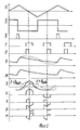
На фиг. 1 представлена функциональная схема устройства; на фиг. 2 - диаграммы работы узлов функциональной схемы. In FIG. 1 shows a functional diagram of a device; in FIG. 2 - diagrams of the operation of the functional circuit nodes.
Устройство управления электромагнитным вибратором содержит задающий генератор 1, фазовый детектор 2, первый двухуровневый компаратор 3, широтно-импульсный модулятор (ШИМ) 4, первый ключ 5, второй ключ 6, электромагнит 7 вибратора, шунтирующий диод 8, управляемый источник тока 9, регулировочный резистор 10 и зарядный конденсатор 11 интегрирующей цепочки, дифференциальный усилитель 12, измерительный шунт 13, третий ключ 14, амплитудный детектор 15, фильтр низких частот 16 и управляемый повторитель-инвертор 17, входящие в состав фазового детектора 2, второй двухуровневый компаратор 18. The electromagnetic vibrator control device comprises a master oscillator 1, a
Работа устройства происходит следующим образом. The operation of the device is as follows.
Пилообразный сигнал с выхода генератора 1 (фиг. 2, а) поступает в ШИМ 4, в котором как результат сравнения с сигналом с блока 15 и с сигналом задания на опорном входе вырабатываются импульсы (фиг. 2, в). Сформированные таким образом импульсы поступают на управляющие входы ключей 5 и 6. Ключ 6 подключает источник стабильного тока 9 к цепочке 10, 11, постоянная времени разряда которой выбирается равной постоянной времени разряда цепи, в которую входит индуктивность электромагнита и последовательно соединенных сопротивления измерительного шунта 13 и диода 8. The sawtooth signal from the output of the generator 1 (Fig. 2, a) enters the PWM 4, in which pulses are generated at the reference input as a result of comparison with the signal from block 15 and with the reference signal at the reference input (Fig. 2, c). The pulses thus generated are fed to the control inputs of the keys 5 and 6. The key 6 connects the stable current source 9 to the circuit 10, 11, the discharge time constant of which is chosen equal to the discharge time constant of the circuit, which includes the inductance of the electromagnet and the resistance of the measuring shunt 13 and diode 8.
Колебания платформы вибратора вызывают изменение воздушного зазора в магнитной цепи и, следовательно, индуктивности колебательной системы, что в свою очередь приводит к появлению в экспоненте разрядного тока гармонической составляющей (фиг. 2, е), однозначно определяющей частоту, амплитуду и фазу колебаний платформы. Дифференциальный усилитель 12 производит вычитание из кривой тока разряда (фиг. 2, е) эталонной экспоненты (фиг. 2, ж), снимаемой с цепочки 10, 11. Результат вычитания в виде искаженной синусоиды (фиг. 2, з) поступает на вход амплитудного детектора 15. За счет изменения ширины импульса (фиг. 2, в) при этом компенсируется действие на платформу вибратора внешних сил. Oscillations of the vibrator platform cause a change in the air gap in the magnetic circuit and, consequently, inductance of the oscillatory system, which in turn leads to the appearance of a harmonic component in the exponent of the discharge current (Fig. 2f), which uniquely determines the frequency, amplitude and phase of the platform oscillations. Differential amplifier 12 subtracts from the curve of the discharge current (Fig. 2, f) the reference exponent (Fig. 2, g) taken from the chain 10, 11. The subtraction result in the form of a distorted sinusoid (Fig. 2, h) is input to the amplitude detector 15. By changing the width of the pulse (Fig. 2, c), this compensates for the effect of external forces on the vibrator platform.
Двухуровневые компараторы вырабатывают импульсы "Строб 1" и "Строб 2" - фиг. 2, г и 2, д. "Строб 1" поступает на управляющий вход ключа 14, что позволяет вырезать из разностного сигнала усилителя 12 симметричный (при f= fрез) относительно максимума участок синусоиды. "Строб 2" делит "Строб 1" пополам, а повторитель-инвертор меняет знак входного сигнала в соответствии с уровнем логического сигнала на своем управляющем входе.Two-level comparators generate pulses "Gate 1" and "
При отклонении частоты колебаний механической системы от частоты fрез меняется соотношение отрицательных и положительных площадей фигур, ограниченных участком синусоиды и "Стробом 1".When the frequency of oscillations of the mechanical system deviates from the frequency f rez, the ratio of the negative and positive areas of the figures bounded by the section of the sinusoid and "Gate 1" changes.
Сигнал рассогласования через фильтр низких частот поступает на управляющий вход генератора 1, замыкая тем самым обратную связь по частоте. The mismatch signal through the low-pass filter is fed to the control input of the generator 1, thereby closing the frequency feedback.
Таким образом, устройство управления обеспечивает автоматическую подстройку частоты задающего генератора на резонанс частоты механической системы и стабилизацию амплитуды механических колебаний. Это позволяет стабилизировать скорость подачи вибропитателем или вибротранспортером деталей в зону обработки при изменении массы механической системы. Thus, the control device provides automatic tuning of the frequency of the master oscillator to the frequency resonance of the mechanical system and stabilization of the amplitude of mechanical vibrations. This makes it possible to stabilize the feed rate by a vibrating feeder or a vibratory conveyor of parts into the processing zone when the mass of the mechanical system changes.
Claims (1)
Priority Applications (1)
| Application Number | Priority Date | Filing Date | Title |
|---|---|---|---|
| SU4636433 RU2024911C1 (en) | 1989-01-12 | 1989-01-12 | Control unit of electromagnetic vibrator |
Applications Claiming Priority (1)
| Application Number | Priority Date | Filing Date | Title |
|---|---|---|---|
| SU4636433 RU2024911C1 (en) | 1989-01-12 | 1989-01-12 | Control unit of electromagnetic vibrator |
Publications (1)
| Publication Number | Publication Date |
|---|---|
| RU2024911C1 true RU2024911C1 (en) | 1994-12-15 |
Family
ID=21422333
Family Applications (1)
| Application Number | Title | Priority Date | Filing Date |
|---|---|---|---|
| SU4636433 RU2024911C1 (en) | 1989-01-12 | 1989-01-12 | Control unit of electromagnetic vibrator |
Country Status (1)
| Country | Link |
|---|---|
| RU (1) | RU2024911C1 (en) |
-
1989
- 1989-01-12 RU SU4636433 patent/RU2024911C1/en active
Non-Patent Citations (2)
| Title |
|---|
| 1. Заявка Великобритании N 2146806, кл. G 05D 19/02, 1983. * |
| 2. Заявка Великобритании N 2073915, кл. G 05D 19/02, 1982. * |
Similar Documents
| Publication | Publication Date | Title |
|---|---|---|
| US4277758A (en) | Ultrasonic wave generating apparatus with voltage-controlled filter | |
| US5216338A (en) | Circuit arrangement for accurately and effectively driving an ultrasonic transducer | |
| WO2001001577A8 (en) | Adjustable bandwidth phase locked loop with fast settling time | |
| US4901034A (en) | Process and circuit for exciting an ultrasonic generator and its use for atomizing a liquid | |
| US6445253B1 (en) | Voltage-controlled oscillator with ac coupling to produce highly accurate duty cycle square wave output | |
| DE59209263D1 (en) | Control device for a vibratory conveyor | |
| EP0978164B1 (en) | Resonator having a selection circuit for selecting a resonance mode | |
| US3826993A (en) | Method for rapidly exciting and sustaining oscillations in a resonant system | |
| RU2024911C1 (en) | Control unit of electromagnetic vibrator | |
| JPS6432113A (en) | Driving method for vibration gyro | |
| ATE125658T1 (en) | CIRCUIT FOR GENERATING A CONTROL SIGNAL UPON THE OCCURANCE OF A PEAK VALUE OF A SINUSOIDAL VIBRATION, AND APPLICATION OF SUCH A CIRCUIT. | |
| ATE75084T1 (en) | OSCILLATOR DEVICE FOR GENERATION OF AT LEAST TWO DIFFERENT FREQUENCIES. | |
| KR100198025B1 (en) | Driving controlling device of vibrator | |
| SU1270671A1 (en) | Method of automatic tuning of ultrasonic transducers | |
| JPS56121112A (en) | Resonant vibrator | |
| RU15461U1 (en) | DEVICE FOR PIESECERAMIC OR MAGNETOSTRICTION CONVERTER POWER SUPPLY | |
| RU2025688C1 (en) | Device to test items for vibration strength | |
| SU1287115A1 (en) | System for determining frequency characteristics of object with pulse-width modulator | |
| SU456332A1 (en) | Source of precision time shifts | |
| SU1465382A1 (en) | Jigging conveyer arrangement | |
| SU1197036A1 (en) | Shock-excited crystal oscillator | |
| SU866714A2 (en) | Charging device | |
| SU469410A1 (en) | Device for automatic adjustment of the cyclic accelerator field | |
| SU1379906A1 (en) | D.c. voltage stabilizing converter | |
| SU1559390A1 (en) | Shock-excited crystal oscillator |