RU2024904C1 - Method of switching optical channels and device for its realization - Google Patents
Method of switching optical channels and device for its realization Download PDFInfo
- Publication number
- RU2024904C1 RU2024904C1 SU5015954A RU2024904C1 RU 2024904 C1 RU2024904 C1 RU 2024904C1 SU 5015954 A SU5015954 A SU 5015954A RU 2024904 C1 RU2024904 C1 RU 2024904C1
- Authority
- RU
- Russia
- Prior art keywords
- optical
- switching
- deflector
- microhologram
- photoreversive
- Prior art date
Links
- 230000003287 optical effect Effects 0.000 title claims abstract description 99
- 238000000034 method Methods 0.000 title claims description 17
- 239000011159 matrix material Substances 0.000 claims abstract description 17
- 108010082845 Bacteriorhodopsins Proteins 0.000 claims abstract description 6
- 230000005855 radiation Effects 0.000 claims description 18
- 238000006073 displacement reaction Methods 0.000 claims description 8
- 229920000642 polymer Polymers 0.000 claims description 3
- 238000003491 array Methods 0.000 claims 1
- 230000007423 decrease Effects 0.000 abstract description 5
- 230000005540 biological transmission Effects 0.000 abstract description 2
- 230000000694 effects Effects 0.000 abstract 1
- 239000000835 fiber Substances 0.000 abstract 1
- 239000000126 substance Substances 0.000 abstract 1
- 238000004891 communication Methods 0.000 description 4
- 230000035945 sensitivity Effects 0.000 description 3
- 230000015556 catabolic process Effects 0.000 description 2
- 238000006731 degradation reaction Methods 0.000 description 2
- 238000010586 diagram Methods 0.000 description 2
- 238000010894 electron beam technology Methods 0.000 description 2
- 238000001093 holography Methods 0.000 description 2
- 230000010365 information processing Effects 0.000 description 2
- 230000007774 longterm Effects 0.000 description 2
- 239000000463 material Substances 0.000 description 2
- 239000011248 coating agent Substances 0.000 description 1
- 238000000576 coating method Methods 0.000 description 1
- 238000005265 energy consumption Methods 0.000 description 1
- 238000005516 engineering process Methods 0.000 description 1
- 238000010438 heat treatment Methods 0.000 description 1
- 230000008929 regeneration Effects 0.000 description 1
- 238000011069 regeneration method Methods 0.000 description 1
- 238000003303 reheating Methods 0.000 description 1
- 230000002269 spontaneous effect Effects 0.000 description 1
- 230000003068 static effect Effects 0.000 description 1
Images

Landscapes
- Holo Graphy (AREA)
Abstract
Description
Изобретение относится к способам дискретного отклонения оптических пучков и может быть использовано в устройствах коммутации широкополосных каналов связи. The invention relates to methods for discrete deflection of optical beams and can be used in switching devices of broadband communication channels.
Известен способ коммутации широкополосных оптических каналов /M.R.Toldman, C. C. Guest Holograms for optical interconnects for very large scale integrated cirquits fabricated by electron beam litography, Opt. Eng., 1989, vol. 28, N 8, p. 915/ заключающийся в том, что между входными и выходными оптическими каналами вдоль оптического пути помещают статические коммутирующие микроголограммы с записью закона коммутации входных каналов в выходные, а при смене закона коммутации старую запись микроголограмм удаляют из коммутатора и на ее место помещают ранее записанные микроголограммы с новым законом коммутации. A Known Method for Switching Broadband Optical Channels / M.R. Toldman, C. C. Guest Holograms for optical interconnects for very large scale integrated cirquits fabricated by electron beam litography, Opt. Eng., 1989, vol. 28,
Недостатком этого способа коммутации является большое время перекоммутации входных оптических каналов в выходные, большое энергопотребление и низкая надежность. The disadvantage of this switching method is the long time of the switching of the input optical channels to the weekend, high power consumption and low reliability.
Известно устройство коммутации по вышеописанному способу /M.R.Toldman, C.C.Guest Holograms for optical interconnects for very large scale integrated cirquits fabricated by electron beam litography, Opt. Eng., 1989, vol. 28, N 8, p. 915/ состоящее из входных оптических каналов, выходных каналов и расположенных между ними коммутирующих микроголограмм. Known switching device according to the above method / M.R. Toldman, C. C. Guest Holograms for optical interconnects for very large scale integrated cirquits fabricated by electron beam litography, Opt. Eng., 1989, vol. 28,
Недостатком этого устройства коммутации является большое время перекоммутации входных оптических каналов в выходные, большое энергопотребление и низкая надежность. The disadvantage of this switching device is the long time of the switching of the input optical channels to the weekend, high power consumption and low reliability.
Наиболее близким к заявляемому способу по технической сущности является способ коммутации оптических каналов /Jean-Yves Moisan, Holographic interconnects using phototermoplastic material, Tech. Dig. Soviet-chinese joint seminar "Holography and optical information processing" (SCJSHOIP-91), Bishkek, Sept. 21-26, 1991, pp. 44-46/ состоящий в том, что вдоль оптического пути между входными и выходными каналами помещают фотореверсивную среду (фототермопласт), коллимированное излучение каждого из входных каналов проецируют на отдельную область фотореверсивной среды, на которую записывают отдельную коммутирующую микроголограмму, обеспечивающую отклонение излучения входного канала в требуемый выходной канал. Для записи каждой микроголограммы всю площадь фототермопласта освещают частью излучения лазера записи коммутирующих микроголограмм, а другую часть этого излучения направляют на фототермопласт под углом пропорциональным требуемой пространственной частоте микроголограммы. После этого на области проекции на фототермопласт излучения соединяемого входного канала проявляют микроголограмму путем локального нагрева этой области. Тем самым записывают микроголограмму с требуемыми для коммутации характеристиками. Для прекращения соединения микроголограмму стирают путем повторного нагрева области проекции излучения входного канала. Для изменения закона коммутации на место стертой микроголограммы записывают новую микроголограмму. Closest to the claimed method according to the technical essence is the method of switching optical channels / Jean-Yves Moisan, Holographic interconnects using phototermoplastic material, Tech. Dig. Soviet-chinese joint seminar "Holography and optical information processing" (SCJSHOIP-91), Bishkek, Sept. 21-26, 1991, pp. 44-46 / consisting in the fact that along the optical path between the input and output channels a photoreversive medium (photothermoplast) is placed, the collimated radiation of each of the input channels is projected onto a separate region of the photoreversive medium, onto which a separate switching microhologram is recorded, which ensures the deviation of the radiation of the input channel into required output channel. To record each microhologram, the entire area of the photothermoplast is illuminated with part of the radiation of the laser for recording commuting microholograms, and the other part of this radiation is directed to the photothermoplast at an angle proportional to the required spatial frequency of the microhologram. After that, a microhologram is shown in the area of the projection onto the photothermoplast of the radiation of the connected input channel by local heating of this area. Thereby, a microhologram is recorded with the characteristics required for switching. To terminate the connection, the microhologram is erased by reheating the projection area of the input channel radiation. To change the law of switching, a new microhologram is recorded in place of the erased microhologram.
Недостатком этого способа коммутации является большое время перекоммутации входных оптических каналов в выходные, большое энергопотребление и низкая надежность. The disadvantage of this switching method is the long time of the switching of the input optical channels to the weekend, high power consumption and low reliability.
Недостатки обусловлены тем, что для перекоммутации требуется долговременный и энергоемкий процесс стирания микроголограмм, что приводит к увеличению времени перекоммутации. Многократная запись и стирание таких микроголограмм приводит к деградации характеристик фотореверсивной среды, увеличению помех коммутации и, как следствие, уменьшению надежности и ограничению ресурса коммутатора. Кроме того наличие в способе аппаратных средств стирания микроголограмм также уменьшает надежность. The disadvantages are due to the fact that for a commutation a long-term and energy-intensive process of erasing microholograms is required, which leads to an increase in the commutation time. Repeated recording and erasing of such microholograms leads to degradation of the characteristics of the photoreversive medium, an increase in switching interference, and, as a result, a decrease in reliability and a limited resource of the switch. In addition, the presence in the method of hardware erasing microholograms also reduces reliability.
Наиболее близким к заявляемому устройству по технической сущности является устройство коммутации оптических каналов /Jean-Yves Moisan, Holographic interconnects using phototermoplastic material, Tech. Dig. Soviet-chinese joint seminar "Holography and optical information processing" (SCJSHOIP-91), Bishkek, Sept. 21-26, 1991, pp. 44-46/, состоящее из входных и выходных оптических каналов, расположенной на оптическом пути между ними фотореверсивной среды (фототермопласта) с нанесенной на нее матрицей электронагревателей, лазера, светоделителя, широкоапертурного дефлектора и двух проекционных оптических систем. Closest to the claimed device in technical essence is an optical channel switching device / Jean-Yves Moisan, Holographic interconnects using phototermoplastic material, Tech. Dig. Soviet-chinese joint seminar "Holography and optical information processing" (SCJSHOIP-91), Bishkek, Sept. 21-26, 1991, pp. 44-46 /, consisting of input and output optical channels located on the optical path between them of a photoreversive medium (photothermoplast) with an array of electric heaters, a laser, a beam splitter, a wide-aperture deflector, and two projection optical systems.
Недостатком этого устройства коммутации является большое время перекоммутации входных оптических каналов в выходные, большое энергопотребление, низкая надежность и ресурс. The disadvantage of this switching device is the long time of the switching of the input optical channels to the weekend, high power consumption, low reliability and resource.
Недостатки обусловлены тем, что для перекоммутации требуется долговременный и энергоемкий процесс стирания микроголограмм, а также низкой эффективностью использования мощности лазера записи микроголограмм. Многократная запись и стирание коммутирующих микроголограмм приводит к деградации характеристик фототермопласта и, как следствие, уменьшению надежности и ресурса коммутатора. Кроме того, наличие в способе аппаратных средств стирания микроголограмм также уменьшает надежность устройства в целом. The disadvantages are due to the fact that for switching, a long-term and energy-intensive process of erasing microholograms is required, as well as low efficiency of using the power of a laser for recording microholograms. Repeated recording and erasing of switching microholograms leads to degradation of the characteristics of the photothermoplast and, as a result, to a decrease in the reliability and resource of the switch. In addition, the presence in the method of hardware erasing microholograms also reduces the reliability of the device as a whole.
Целью изобретения является уменьшение энергопотребления, времени перекоммутации входных оптических каналов в выходные и увеличение надежности и ресурса. The aim of the invention is to reduce power consumption, the time of the switching of the input optical channels in the weekend and increase reliability and resource.
Поставленная цель достигается тем, что в способе коммутации оптических каналов, состоящем в том, что вдоль оптического пути между входными и выходными каналами помещают фотореверсивную среду, коллимированное излучение каждого из входных каналов проецируют на отдельную область фотореверсивной среды, на которую в начале коммутации лазером записывают отдельную коммутирующую микроголограмму, обеспечивающую отклонение излучения входного канала в требуемый выходной канал, а по окончании коммутации микроголограмму стирают, каждый маршрут соединения предварительно запоминают в ячейке памяти в виде информации о пространственной частоте и местоположении коммутирующей микроголограммы, информацию из ячейки считывают, по считанной информации записывают коммутирующую микроголограмму, причем в течение соединения считывание из ячейки периодически повторяют, а при окончании соединения информацию из ячейки стирают, причем для записи микроголограммы по информации о пространственной частоте коммутирующей микроголограммы световой пучок лазера пространственно смещают (параллельно оптической оси) на расстояние, пропорциональное требуемой пространственной частоте регистрируемой микроголограммы, затем делят его на два пучка, один из которых по информации о местоположении коммутирующей микроголограммы отклоняют на угол пропорциональный местоположению на фотореверсивной среде проекции светового пучка коммутируемого канала, а второй сначала смещают по направлению к оптической оси на расстояние, пропорциональное смещению от оптической оси первого пучка, а затем отклоняют на угол, равный углу отклонения первого пучка, после чего первый и второй пучки сводят оптической системой на фотореверсивной среде в одно пятно. This goal is achieved by the fact that in the method of switching optical channels, which consists in the fact that along the optical path between the input and output channels a photoreversive medium is placed, the collimated radiation of each of the input channels is projected onto a separate region of the photoreversive medium, onto which a separate laser is recorded a switching micro-hologram, providing a deviation of the radiation of the input channel to the desired output channel, and at the end of the switching, the micro-hologram is erased, each route the connections are preliminarily stored in the memory cell in the form of information about the spatial frequency and location of the switching microhologram, the information from the cell is read, the switching microhologram is written from the read information, and during the connection the reading from the cell is periodically repeated, and when the connection is completed, the information from the cell is erased, and for recording of a hologram according to information about the spatial frequency of the switching microhologram, the laser light beam is spatially shifted (parallel the optical axis) by a distance proportional to the required spatial frequency of the recorded microhologram, then divide it into two beams, one of which, according to the location of the switching microhologram, is rejected by an angle proportional to the location on the photoreversive medium of the projection of the light beam of the switched channel, and the second is first shifted in the direction to the optical axis by a distance proportional to the offset from the optical axis of the first beam, and then deflected by an angle equal to the angle of deviation of the first beam, after which the first and second beams are brought together by the optical system on a photoreversive medium in one spot.
Поставленная цель в реализующем способ устройстве достигается тем, что устройство коммутации оптических каналов, содержащее входные и выходные коммутируемые оптические каналы, фотореверсивную среду, лазер и светоделитель, устройство дополнительно содержит первый дефлектор, оптический элемент смещения светового пучка в направлении оптической оси, второй дефлектор, оптическую систему, блок памяти, блок управления первым дефлектором и блок управления вторым дефлектором, причем вдоль оптической оси лазера последовательно установлены и оптически связаны первый дефлектор, светоделитель, одна из оптических осей которого связана со вторым дефлектором непосредственно, а вторая ось связана через оптический элемент смещения светового пучка в направлении оптической оси тоже со вторым дефлектором, за которым расположена оптическая система, выполненная и установленная с возможностью сведения первой и второй оси в одну точку, расположенную на фотореверсивной среде, на которую спроецированы оптические оси входных и выходных каналов, причем первый дефлектор электрически связан с блоком памяти через блок управления первым дефлектором, а второй дефлектор связан с блоком памяти через блок управления вторым дефлектором, при этом первый дефлектор представляет собой последовательно расположенные вдоль оптической оси акустооптическую ячейку и оптическую систему, установленную на фокусном расстоянии от акустооптической ячейки, а в качестве второго дефлектора используется акустооптическая ячейка с секционированным пьезопреобразователем, выполненная с возможностью независимого подключения управляющего сигнала к любой из секций, и кроме того второй дефлектор выполнен в виде двух одинаковых устройств, соединенных с единым источником управляющих сигналов, и при этом первый и второй дефлекторы выполнены в виде двумерных отклоняющих устройств, а оптический элемент смещения светового пучка в направлении оптической оси выполнен в виде трех последовательно расположенных и оптически связанных плоских зеркал, причем плоскость первого и второго зеркала образует прямой угол, а плоскость третьего зеркала образует с плоскостью первого и второго угол 45о, а с целью увеличения вибростойкости, светоделитель и элемент смещения светового пучка выполнены в виде конфокальной оптической системы, одним из оптических элементов которой служит голографическая линза, выполненная и установленная с возможностью прохождения недифрагированного на ней светового пучка вне световой апертуры расположенных за голографической линзой оптических элементов, и при этом одним из компонентов состава фотореверсивной среды является бактериородопсин.The goal in the device implementing the method is achieved in that the optical channel switching device comprising input and output switched optical channels, a photoreversive medium, a laser and a beam splitter, the device further comprises a first deflector, an optical element for displacing the light beam in the direction of the optical axis, a second deflector, an optical a system, a memory unit, a control unit for the first deflector and a control unit for the second deflector, moreover, installed along the optical axis of the laser and optically coupled to the first deflector, a beam splitter, one of the optical axes of which is directly connected to the second deflector, and the second axis is also connected via the optical element for displacing the light beam in the direction of the optical axis to the second deflector, behind which there is an optical system made and installed to reduce the first and the second axis at one point located on the photoreversive medium onto which the optical axes of the input and output channels are projected, the first deflector being electrically connected n to the memory unit through the control unit of the first deflector, and the second deflector is connected to the memory unit through the control unit of the second deflector, wherein the first deflector is an acousto-optic cell sequentially located along the optical axis and an optical system mounted at a focal length from the acousto-optic cell, and in as the second deflector, an acousto-optical cell with a sectioned piezoelectric transducer is used, made with the possibility of independent connection of the control signal and to any of the sections, and in addition, the second deflector is made in the form of two identical devices connected to a single source of control signals, and the first and second deflectors are made in the form of two-dimensional deflecting devices, and the optical element for displacing the light beam in the direction of the optical axis is made in the form of three consecutively located and optically coupled plane mirrors, the plane of the first and second mirrors forming a right angle, and the plane of the third mirror forming an angle 45 with the plane of the first and second o , and in order to increase the vibration resistance, the beam splitter and the light beam displacement element are made in the form of a confocal optical system, one of the optical elements of which is a holographic lens, made and installed with the possibility of passing an undiffracted light beam outside the light aperture of the optical elements behind the holographic lens , and one of the components of the composition of the photoreversive medium is bacteriorhodopsin.
Изучение и анализ известной научно-технической и патентной литературы показал, что полной совокупности признаков, характеризующих данные технические решения ранее не известно, т.е. заявляемые решения отвечают критерию "новизна". The study and analysis of the well-known scientific, technical and patent literature showed that the full set of features characterizing these technical solutions was not previously known, i.e. The claimed solutions meet the criterion of "novelty."
Поиск, проведенный в науке и технике, показал также отсутствие решений, содержащих полную совокупность признаков сходных с отличительными признаками заявляемого способа и устройства. Кроме того, отличительные признаки проявляют в заявляемых объектах новое свойство, заключающееся в использовании для реализации полнодоступной схемы оптического переключения N широкополосных каналов динамического режима фотореверсивной среды и только двух малоапертурных быстродействующих, активно управляемых переключателей света на N позиций, а также экономичного лазера записи с непрерывным излучением. В то время, как в известных коммутаторах оптических каналов для реализации полнодоступной схемы оптического переключения N широкополосных каналов связи требуется фотореверсивная среда, требующая дополнительной операции стирания, и как минимум один активно управляемый переключатель света с большой апертурой, имеющий по этой причине низкое быстродействие. Поэтому следует признать, что заявляемые решения соответствуют критерию "существенные отличия". A search conducted in science and technology, also showed the absence of solutions containing a complete set of features similar to the hallmarks of the proposed method and device. In addition, the distinctive features exhibit a new property in the claimed objects, which consists in using only two low-aperture high-speed, actively controlled light switches at N positions, as well as an economical continuous-wave recording laser for the implementation of a fully accessible optical switching scheme for N wideband channels of the dynamic mode of a photoreversive medium . At the same time, in the well-known optical channel switches, the implementation of a fully accessible optical switching scheme for N broadband communication channels requires a photoreversive medium that requires an additional erasing operation, and at least one actively controlled light switch with a large aperture, which for this reason has low speed. Therefore, it should be recognized that the claimed solutions meet the criterion of "significant differences".
На фиг. 1 изображена структурная схема коммутатора оптических каналов. In FIG. 1 shows a block diagram of an optical channel switch.
Согласно схеме из коммутируемых (10.000) оптических каналов сформированы две матрицы - матрица входных каналов 1 и матрица выходных каналов 2. Матрицы имеют размерность - 100 х 100 элементов, а их приблизительные линейные размеры - 100 мм х 100 мм. Излучение элементов входной матрицы 1 коллимировано до размера ≈1 мм2 и спроектировано в виде неперекрывающихся в пространстве световых пучков на фотореверсивной среде (ФС) 3 с ограниченным временем хранения записанной на ней информации. В качестве фотореверсивной среды используется носитель на основе модифицированного бактериородопсина в полимерной матрице с реверсивностью более 107 циклов записи-считывания, на который дополнительно нанесено отражающее излучение входных каналов покрытие. За ФС 3 расположена оптическая схема записи на ФС 3 микроголограмм, состоящая из лазера 4, длина волны излучения которого лежит в области чувствительности ФС 3, первого акустооптического дефлектора 5, соединенного через блок управления первым дефлектором 6 с блоком памяти адресов коммутаций 7, оптической системы 8, светоделителя 9, оптического элемента смещения светового пучка в направлении оптической оси 10, второго акустооптического дефлектора 11, соединенного через блок управления вторым дефлектором 12 с блоком памяти адресов коммутаций 7, и оптической системы 13.According to the scheme, two matrices are formed from the switched (10,000) optical channels — the input channel 1 matrix and the
Для коммутации очередного входного канала матрицы 1 с выходным каналом 2 на ФС 3, в области проекции на ней излучения входного канала матрицы 1 записывается микроголограмма с пространственной частотой, обеспечивающей отклонение светового пучка коммутируемого канала матрицы 1, в нужный выходной канал матрицы 2. Запись всех микроголограмм, определяющих закон коммутаций всех каналов, производится последовательно и осуществляется следующим образом. To switch the next input channel of the matrix 1 with the
Для записи очередной микроголограммы опрашивается очередная ячейка памяти 7, в которой содержится информация о пространственной частоте и местоположении коммутирующей микроголограммы. По информации о пространственной частоте блок управления первым дефлектором 6 формирует сигнал управления дефлектором 5, а по информации о местоположении коммутирующей микроголограммы блок управления вторым дефлектором 12 формирует сигнал управления дефлектором 11. По этим сигналам дефлектор 5 отклоняет световой пучок лазера на угол, пропорциональный требуемой пространственной частоте микроголограммы. Оптическая система 8 преобразует угловое отклонение пучка в линейное смещение параллельно оптической оси. Смещенный световой пучок падает на светоделитель 9, где часть его интенсивности отражается на вход дефлектора 11. Прошедшая через светоделитель 9 вторая часть пучка попадает в оптический элемент смещения светового пучка в направлении оптической оси 10, выполненный в виде трех плоских зеркал, из которых плоскости первых двух образуют прямой угол, а плоскость третьего составляет 45о с плоскостями первых двух. С выхода 10 второй пучок поступает на вход дефлектора 11. Дефлектор 11 отклоняет первый и второй пучки на одинаковый угол, пропорциональный требуемому местоположению микроголограммы на ФС 3. Оба световых пучка с выхода дефлектора 11 оптическая система 13 сводит (в своей задней фокальной плоскости) на ФС 3 в пятно записи микроголограммы. При этом местоположение пятна на ФС 3 определяется углом отклонения пучков дефлектором 11 и находится в месте проекции излучения требуемого входного канала на ФС 3, а угол схождения пучков определяется дефлектором 5 и имеет величину, необходимую для записи на ФС 3 микроголограммы с нужными для попадания светового пучка входного канала матрицы 1 в выходной канал матрицы 2 характеристиками. Последовательным опросом памяти 7 обеспечивается запись всех микроголограмм на ФС 3. Этим достигается параллельное оптическое соединение между каналами матриц 1 и 2 по заданному закону. Для поддержания соединения между коммутируемыми каналами в течение сеанса связи микроголограммы на ФС 3 регенерируются путем периодического опроса памяти 7, повторения записи, и восстановления за счет этого отклоняющих свойств микроголограмм. Отключение соединения между каналами (сеанс связи между которыми закончился) осуществляется при прекращении регенерации соответствующих микроголограмм за счет самопроизвольного их стирания излучением входных каналов. Записью на место стертых микроголограмм микроголограмм с новыми характеристиками достигается изменение закона коммутаций.To record the next microhologram, the next memory cell 7 is interrogated, which contains information about the spatial frequency and location of the switching microhologram. According to information about the spatial frequency, the control unit of the
Еще большее увеличение надежности устройства достигается за счет применения в качестве светоделителя 9 и оптического элемента смещения светового пучка в направлении оптической оси 10 конфокальной оптической системы, одним из оптических элементов которой служит голографическая линза. An even greater increase in the reliability of the device is achieved through the use of a
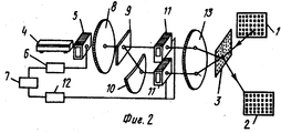
На фиг. 2 изображена структурная схема коммутатора оптических каналов с конфокальной оптической системой. In FIG. 2 shows a block diagram of an optical channel switch with a confocal optical system.
Коммутатор состоит из матрицы входных каналов 1, матрицы выходных каналов 2, фотореверсивной среды 3 (ФС 3), лазера 4, первого акустооптического дефлектора 5, соединенного через блок управления первым дефлектором 6 с блоком памяти адресов коммутаций 7, оптической системы 8, голографической сферической линзы 9, конфокально установленной с 9 сферической линзы 10, второго акустооптического дефлектора 11, выполненного в виде двух, управляющих каждый своим световым пучком одинаковых акустооптических дефлекторов, соединенных через блок управления вторым дефлектором 12 с блоком памяти адресов коммутаций 7, и оптической системы 13. The switch consists of a matrix of input channels 1, a matrix of
Запись всех микроголограмм, определяющих закон коммутаций всех каналом, производится последовательно и осуществляется следующим образом. Record of all microholograms that determine the law of switching of all channels is performed sequentially and is carried out as follows.
Для записи очередной микроголограммы опрашивается очередная ячейка памяти 7, в которой содержится информация о пространственной частоте и местоположении коммутирующей микроголограммы. По информации о пространственной частоте блок управления первым дефлектором 6 формирует сигнал управления дефлектором 5, а по информации о местоположении коммутирующей микроголограммы блок управления вторым дефлектором 12 формирует сигнал управления дефлектором 11. По этим сигналам дефлектор 5 отклоняет световой пучок лазера на угол, пропорциональный требуемой пространственной частоте микроголограммы. Оптическая система 8 преобразует угловое отклонение пучка в линейное смещение параллельно оптической оси. Смещенный световой пучок падает на голографическую линзу 9, дифракционная эффективность которой приблизительно равна 50%. Часть интенсивности светового пучка проходит сквозь голографическую линзу 9 без изменения направления на вход дефлектора 11. Вторая часть интенсивности светового пучка фокусируется линзой 9 и одновременно смещается в направлении оптической оси. Сферическая линза 10 делает параллельный второй пучок и направляет его параллельно первому на вход дефлектора 11. Дефлектор 11 отклоняет первый и второй пучки на одинаковый угол, пропорциональный требуемому местоположению микроголограммы на ФС 3. Оба световых пучка с выхода дефлектора 11 оптическая система 13 сводит (в своей задней фокальной плоскости) на ФС 3 в пятно записи микроголограммы. При этом местоположение пятна на ФС 3 определяется углом отклонения пучков дефлектором 11 и находится в месте проекции излучения требуемого входного канала на ФС 3, а угол схождения пучков определяется дефлектором 5 и имеет величину необходимую для записи на ФС 3 микроголограммы с нужными для попадания светового пучка входного канала матрицы 1 в выходной канал матрицы 2 характеристиками. To record the next microhologram, the next memory cell 7 is interrogated, which contains information about the spatial frequency and location of the switching microhologram. According to information about the spatial frequency, the control unit of the
Дефлекторы 5 и 11 обеспечивают по каждой из ортогональных координат 100 положений. При дифракционной эффективности порядка 50% тpебуемая мощность на их управление гораздо меньше чем у прототипа и оценивается в 0,3-1 Вт, а время их переключения в произвольное направление - в 20-50 мкс, что также меньше чем у прототипа. При этом на отключение соединения энергия не расходуется. За счет уменьшения рабочей апертуры управляющих светом элементов и амплитуды управляющих сигналов надежность коммутатора увеличивается, поскольку снижается вероятность выхода из строя устройства из-за повреждения активных элементов и устройства стирания голограмм. Требуемая средняя мощность лазера 4 оценивается по формуле P≈HS/cNτ, где Н - чувствительность фотореверсивной среды, в качестве которой использован модифицированный бактериородопсин в полимерной матрице; S - площадь световой апертуры ФС; с - пропускание оптического тракта; τ -время коммутации. При H≈10-3 Дж/см2 (типичная чувствительность среды на основе бактериородопсина), S≈100 см2, с≈ 0,1, τ ≈ 10-3 с Р≈1 Вт. При КПД лазера около 5% это соответствует энергопотреблению около 20 Вт. Таким образом, при поле полнодоступных коммутаций 10.000 х 10.000 каналов, время коммутации составит менее 10-3 с, энергопотребление не превысит 30 Вт.Deflectors 5 and 11 provide for each of the orthogonal coordinates 100 positions. With a diffraction efficiency of about 50%, the required power for their control is much less than that of the prototype and is estimated at 0.3-1 W, and the time of their switching in an arbitrary direction is 20-50 μs, which is also less than that of the prototype. At the same time, disconnecting the connection does not consume energy. By reducing the working aperture of the light-controlling elements and the amplitude of the control signals, the reliability of the switch increases, since the probability of device failure due to damage to active elements and the device for erasing holograms decreases. The required average laser power 4 is estimated by the formula P≈HS / cNτ, where H is the sensitivity of the photoreversive medium, which is used as modified bacteriorhodopsin in a polymer matrix; S is the area of the light aperture of the FS; c - transmission of the optical path; τ is the switching time. At H≈10 -3 J / cm 2 (typical sensitivity of the medium based on bacteriorhodopsin), S≈100 cm 2 , s≈ 0.1, τ ≈ 10 -3 s P≈1 W. With a laser efficiency of about 5%, this corresponds to an energy consumption of about 20 watts. Thus, with a field of fully accessible switching 10,000 x 10,000 channels, the switching time will be less than 10 -3 s, power consumption will not exceed 30 watts.
Claims (11)
Priority Applications (1)
| Application Number | Priority Date | Filing Date | Title |
|---|---|---|---|
| SU5015954 RU2024904C1 (en) | 1991-12-04 | 1991-12-04 | Method of switching optical channels and device for its realization |
Applications Claiming Priority (1)
| Application Number | Priority Date | Filing Date | Title |
|---|---|---|---|
| SU5015954 RU2024904C1 (en) | 1991-12-04 | 1991-12-04 | Method of switching optical channels and device for its realization |
Publications (1)
| Publication Number | Publication Date |
|---|---|
| RU2024904C1 true RU2024904C1 (en) | 1994-12-15 |
Family
ID=21591249
Family Applications (1)
| Application Number | Title | Priority Date | Filing Date |
|---|---|---|---|
| SU5015954 RU2024904C1 (en) | 1991-12-04 | 1991-12-04 | Method of switching optical channels and device for its realization |
Country Status (1)
| Country | Link |
|---|---|
| RU (1) | RU2024904C1 (en) |
Cited By (2)
| Publication number | Priority date | Publication date | Assignee | Title |
|---|---|---|---|---|
| RU2343517C2 (en) * | 2004-07-28 | 2009-01-10 | Владимир Алексеевич Шульгин | Polarisation-independent acoustooptical fibre-optic commutator |
| RU2704630C1 (en) * | 2017-11-27 | 2019-10-30 | Кэнон Кабусики Кайся | Vibration-type motor, lens device and electronic device |
-
1991
- 1991-12-04 RU SU5015954 patent/RU2024904C1/en active
Non-Patent Citations (2)
| Title |
|---|
| Jean-Yves Moisan, Holographic interconnects usiug phototermoplastic material, Tech. Dig. Soviet-chinese joint seminar "Holography and optical information processing" (SCJSH01P-91), Bishrer, Sept, 21-26, 1991, pp 44-46. * |
| M.R.Toldma, C.C.Guest Holograms for optical interconnects for very large scale integrated cirguits fabricated by electron beam litography, Opt.Eng. 1989, vol. 28, N 8, p.915. * |
Cited By (3)
| Publication number | Priority date | Publication date | Assignee | Title |
|---|---|---|---|---|
| RU2343517C2 (en) * | 2004-07-28 | 2009-01-10 | Владимир Алексеевич Шульгин | Polarisation-independent acoustooptical fibre-optic commutator |
| RU2704630C1 (en) * | 2017-11-27 | 2019-10-30 | Кэнон Кабусики Кайся | Vibration-type motor, lens device and electronic device |
| US11418134B2 (en) | 2017-11-27 | 2022-08-16 | Canon Kabushiki Kaisha | Vibration type motor for guiding movement of a friction member, and lens apparatus and electronic apparatus including said motor |
Similar Documents
| Publication | Publication Date | Title |
|---|---|---|
| US3980818A (en) | Recorder and reproducer system | |
| US3831035A (en) | Switching network for information channels, preferably in the optical frequency range | |
| Burr et al. | Angle and space multiplexed holographic storage using the 90 geometry | |
| US5481523A (en) | Gantry for positioning a read/write head of a holographic information storage system | |
| JPH06504633A (en) | optical phased array | |
| US5436867A (en) | Holographic random access memory | |
| US4403352A (en) | Switching device for optical beams and telephone exchange incorporating such a device | |
| WO1996015475A1 (en) | Laser scanner incorporating variable focus mechanism for rapidly changing beam spot size | |
| US4712207A (en) | Apparatus for erasing information on a reversible optical recording medium | |
| US3838912A (en) | Optical deflecting apparatus | |
| RU2024904C1 (en) | Method of switching optical channels and device for its realization | |
| GB2231709A (en) | Light scanning device | |
| US3703137A (en) | High-speed printing apparatus | |
| EP0207164B1 (en) | Apparatus for recording and reproducing optical recording card | |
| CN116974053A (en) | Light emitting device and solid-state lidar based on spatial light modulator | |
| GB2326735A (en) | Volume holographic data storage system having cylindrical storage medium | |
| JPH0738258B2 (en) | Optical memory with sample tracking for pre-format information media | |
| US3719409A (en) | Array of focusing holograms | |
| GB2189038A (en) | Optical switching | |
| US3432771A (en) | Optical scanning techniques employing an optical cavity including two reflectors and a focussing objective | |
| Mikaelian et al. | High-capacity optical spatial switch based on reversible holograms | |
| US3990771A (en) | Apparatus and method for holographic storage of data | |
| US3836224A (en) | Holdgram memory readout system | |
| US6292300B1 (en) | Apparatus for generating independent coherent beam array using 45-degree mirrors | |
| US3627405A (en) | Acousto-optic light deflection |