RU2019653C1 - Butt joint of member surfaces - Google Patents
Butt joint of member surfaces Download PDFInfo
- Publication number
- RU2019653C1 RU2019653C1 SU894613933A SU4613933A RU2019653C1 RU 2019653 C1 RU2019653 C1 RU 2019653C1 SU 894613933 A SU894613933 A SU 894613933A SU 4613933 A SU4613933 A SU 4613933A RU 2019653 C1 RU2019653 C1 RU 2019653C1
- Authority
- RU
- Russia
- Prior art keywords
- elements
- faces
- edges
- connection
- positioning
- Prior art date
Links
- 210000001503 joint Anatomy 0.000 title 1
- 230000013011 mating Effects 0.000 claims abstract description 8
- 230000015572 biosynthetic process Effects 0.000 claims 1
- 150000001875 compounds Chemical class 0.000 claims 1
- 238000010276 construction Methods 0.000 abstract description 2
- 239000000126 substance Substances 0.000 abstract 1
- 238000003032 molecular docking Methods 0.000 description 11
- 238000005304 joining Methods 0.000 description 6
- 230000033001 locomotion Effects 0.000 description 6
- 239000000463 material Substances 0.000 description 4
- 230000008901 benefit Effects 0.000 description 3
- 230000005540 biological transmission Effects 0.000 description 2
- 238000009826 distribution Methods 0.000 description 2
- 238000009472 formulation Methods 0.000 description 2
- 238000004519 manufacturing process Methods 0.000 description 2
- 238000000034 method Methods 0.000 description 2
- 239000000203 mixture Substances 0.000 description 2
- 238000007493 shaping process Methods 0.000 description 2
- 230000002146 bilateral effect Effects 0.000 description 1
- 239000004568 cement Substances 0.000 description 1
- 238000004891 communication Methods 0.000 description 1
- 238000011109 contamination Methods 0.000 description 1
- 230000008878 coupling Effects 0.000 description 1
- 238000010168 coupling process Methods 0.000 description 1
- 238000005859 coupling reaction Methods 0.000 description 1
- 238000013016 damping Methods 0.000 description 1
- 230000001419 dependent effect Effects 0.000 description 1
- 230000005489 elastic deformation Effects 0.000 description 1
- 239000013013 elastic material Substances 0.000 description 1
- 238000005516 engineering process Methods 0.000 description 1
- 239000003292 glue Substances 0.000 description 1
- 238000003780 insertion Methods 0.000 description 1
- 230000037431 insertion Effects 0.000 description 1
- 230000002452 interceptive effect Effects 0.000 description 1
- 230000008569 process Effects 0.000 description 1
- 230000000750 progressive effect Effects 0.000 description 1
- 230000003068 static effect Effects 0.000 description 1
- 238000004381 surface treatment Methods 0.000 description 1
- 238000012546 transfer Methods 0.000 description 1
- 230000007704 transition Effects 0.000 description 1
Images


Classifications
-
- E—FIXED CONSTRUCTIONS
- E04—BUILDING
- E04B—GENERAL BUILDING CONSTRUCTIONS; WALLS, e.g. PARTITIONS; ROOFS; FLOORS; CEILINGS; INSULATION OR OTHER PROTECTION OF BUILDINGS
- E04B1/00—Constructions in general; Structures which are not restricted either to walls, e.g. partitions, or floors or ceilings or roofs
- E04B1/38—Connections for building structures in general
- E04B1/541—Joints substantially without separate connecting elements, e.g. jointing by inter-engagement
-
- B—PERFORMING OPERATIONS; TRANSPORTING
- B23—MACHINE TOOLS; METAL-WORKING NOT OTHERWISE PROVIDED FOR
- B23Q—DETAILS, COMPONENTS, OR ACCESSORIES FOR MACHINE TOOLS, e.g. ARRANGEMENTS FOR COPYING OR CONTROLLING; MACHINE TOOLS IN GENERAL CHARACTERISED BY THE CONSTRUCTION OF PARTICULAR DETAILS OR COMPONENTS; COMBINATIONS OR ASSOCIATIONS OF METAL-WORKING MACHINES, NOT DIRECTED TO A PARTICULAR RESULT
- B23Q3/00—Devices holding, supporting, or positioning work or tools, of a kind normally removable from the machine
- B23Q3/02—Devices holding, supporting, or positioning work or tools, of a kind normally removable from the machine for mounting on a work-table, tool-slide, or analogous part
- B23Q3/10—Auxiliary devices, e.g. bolsters, extension members
- B23Q3/103—Constructional elements used for constructing work holders
-
- B—PERFORMING OPERATIONS; TRANSPORTING
- B23—MACHINE TOOLS; METAL-WORKING NOT OTHERWISE PROVIDED FOR
- B23Q—DETAILS, COMPONENTS, OR ACCESSORIES FOR MACHINE TOOLS, e.g. ARRANGEMENTS FOR COPYING OR CONTROLLING; MACHINE TOOLS IN GENERAL CHARACTERISED BY THE CONSTRUCTION OF PARTICULAR DETAILS OR COMPONENTS; COMBINATIONS OR ASSOCIATIONS OF METAL-WORKING MACHINES, NOT DIRECTED TO A PARTICULAR RESULT
- B23Q16/00—Equipment for precise positioning of tool or work into particular locations not otherwise provided for
-
- E—FIXED CONSTRUCTIONS
- E04—BUILDING
- E04B—GENERAL BUILDING CONSTRUCTIONS; WALLS, e.g. PARTITIONS; ROOFS; FLOORS; CEILINGS; INSULATION OR OTHER PROTECTION OF BUILDINGS
- E04B1/00—Constructions in general; Structures which are not restricted either to walls, e.g. partitions, or floors or ceilings or roofs
- E04B1/02—Structures consisting primarily of load-supporting, block-shaped, or slab-shaped elements
- E04B1/10—Structures consisting primarily of load-supporting, block-shaped, or slab-shaped elements the elements consisting of wood
-
- E—FIXED CONSTRUCTIONS
- E04—BUILDING
- E04B—GENERAL BUILDING CONSTRUCTIONS; WALLS, e.g. PARTITIONS; ROOFS; FLOORS; CEILINGS; INSULATION OR OTHER PROTECTION OF BUILDINGS
- E04B1/00—Constructions in general; Structures which are not restricted either to walls, e.g. partitions, or floors or ceilings or roofs
- E04B1/38—Connections for building structures in general
Abstract
Description
Изобретение касается соединений стыковочных поверхностей, элемента, который стыкуется с соответствующим образом сложно выполненными контрповерхностями, для направления и/или позиционирования конструктивных элементов. The invention relates to joints of mating surfaces, an element that fits into appropriately difficult counter surfaces to guide and / or position structural elements.
В качестве стыковочных поверхностей при этом понимают состыкование друг с другом поверхности элементов, имеющих соответствующую конфигурацию поверхностей. In this case, as the mating surfaces, it is understood that the surfaces of elements having an appropriate surface configuration are mated with each other.
В соответствии со специальными свойствами соответствующего изобретению соединения стыковочных поверхностей оно используется для решения разнообразных задач в отношении поверхностей соответствующих технических тел, которые в данном случае называют конструктивными элементами, или представляют собой в основном их поверхность. In accordance with the special properties of the joint of the connecting surfaces according to the invention, it is used to solve various problems with respect to the surfaces of the corresponding technical bodies, which in this case are called structural elements, or represent mainly their surface.
Предпочтительные использования возникают, в частности, при решении задач зажимания, позиционирования и соединения, как при статическом использовании, так и при передаче движения применительно к технике сооружений, машин и установок, а также строительной технике. Preferred uses arise, in particular, when solving problems of clamping, positioning and joining, both in static use and in the transmission of motion as applied to the technology of structures, machines and plants, as well as construction equipment.
Известны разнообразные исполнения и возможности использования соединений стыковочных поверхностей. Они выполняют в общем случае задачи, которые заключаются в направлении одного тела на другом по определенной траектории или в их фиксации в определенной позиции, то есть в позиционировании. Для передачи усилий при этом часто используются дополнительные элементы с силовым или геометрическим замыканием, например, винты. A variety of designs and the possibilities of using joints of docking surfaces are known. In the general case, they perform tasks that consist in the direction of one body on another along a certain trajectory or in their fixation in a certain position, that is, in positioning. In this case, additional elements with a power or geometric closure, for example, screws, are often used to transmit forces.
Простейшие известные элементы представляют собой гладкие поверхности. Осуществляемое с геометрическим замыканием направление или позиционирование реализуется в данном случае с помощью дополнительных элементов, например, штифтов, осей и упоров. Для перехода от функции "направление" к функции "позиционирование" и наоборот, при этом в большинстве случаев возникает необходимость в удалении или добавлении дополнительных элементов или же в внесении дополнительных посторонних функций позиционирования или их устранения. Во многих случаях, однако, используется преимущественно или исключительно лишь одна из обеих функций, которая определяет, таким образом, конфигурацию стыковочных поверхностей. The simplest known elements are smooth surfaces. The direction or positioning carried out with a geometric closure is realized in this case with the help of additional elements, for example, pins, axles and stops. To move from the “direction” function to the “positioning” function and vice versa, in most cases there is a need to remove or add additional elements or to introduce additional extraneous positioning functions or to eliminate them. In many cases, however, only one of the two functions is used predominantly or exclusively, which thus determines the configuration of the mating surfaces.
В случае общей постановки задачи "направление" реализуемые с геометрическим замыканием фиксирующие позиции оказывают в большинстве случаев мешающее влияние и поэтому не предусматриваются. In the case of the general formulation of the “direction” problem, the locking positions implemented with a geometric closure in most cases have an interfering effect and are therefore not foreseen.
В случае сложных стыковочных поверхностей для постановки задачи в форме "позиционирование" направляющая функция ограничивается в большинстве случаев введением контрповерхности в позицию фиксации с помощью скосов или подобных элементов. В случае двух известных устройств для позиционирования конструктивных элементов между двумя стыковочными поверхностями, которые оснащены позиционирующими отверстиями или позиционирующими пазами, при несколько дорогостоящей манипуляции вводятся дополнительные, имеющие форму шара или цилиндра элементы, с помощью которых достигается позиционирование обеих поверхностей. Также в этом случае направляющая функция скошенных стенок с отверстиями или пазами является ограниченной и служит преимущественно для обоюдосторонней точной центровки обеих стыковочных поверхностей (1). In the case of complex connecting surfaces for setting the problem in the form of "positioning", the guiding function is limited in most cases by introducing the counter-surface into the fixation position using bevels or similar elements. In the case of two known devices for positioning structural elements between two connecting surfaces, which are equipped with positioning holes or positioning grooves, with a little expensive manipulation, additional ball-shaped or cylinder-shaped elements are introduced with which the positioning of both surfaces is achieved. Also in this case, the guiding function of the beveled walls with holes or grooves is limited and serves mainly for bilateral accurate alignment of both connecting surfaces (1).
Аналогичные ограничения функции направления, а также переменной функции позиционирования характерны для известных стыковочных поверхностей, которые содержат на обращенных друг к другу поверхностях прилегания сложные относительно друг друга, оснащенные кромками профили, которые взаимно опираются друг о друга исключительно этими кромками (2). Similar limitations of the direction function, as well as the variable positioning function, are characteristic of known docking surfaces that contain abutment profiles that are complex with respect to each other on facing surfaces facing each other, and which mutually rely on each other exclusively by these edges (2).
При равнозначной постановке задачи "Направление" вдоль направляющих осей и "Позиционирование" в позициях фиксации, например, в известных, оснащенных кулачковыми дисками предохранительных муфтах, задача направления соответствующих поверхностей или краев ограничивается обеспечением возможности точного перехода от одной позиции фиксации к другой в случае возникновения перегрузки. Достижение с помощью опорной функции дальнейших позиций вдоль направляющих осей оказывается при этом невозможным. То же справедливо в отношении известных, самоцентрирующихся частей и позиционирующих колец с коническим внешним зубчатым венцом (торцовые зубья). With the equivalent formulation of the “Direction” task along the guide axes and “Positioning” in the locking positions, for example, in the known safety couplings equipped with cam discs, the task of guiding the corresponding surfaces or edges is limited to ensuring the possibility of an exact transition from one locking position to another in case of overload . It is not possible to achieve further positions along the guide axes using the support function. The same is true for known, self-centering parts and positioning rings with a conical external gear rim (end teeth).
Вследствие того, что - аналогично обоим упомянутым выше примерам - позиция фиксации достигается часто посредством стыковки (положительного) выступа поверхности с соответствующим (отрицательным) углублением, в данном случае можно отметить существенный недостаток таких методов стыковки. Покидание позиции фиксации требует значительного движения разъема обеих стыковочных поверхностей поперечно направлению желаемого дальнейшего движения с тем, чтобы обеспечить выход возвышения поверхности одной стороны из углубления другой стороны и переход через следующее возвышение другой стороны. Due to the fact that - similarly to the two examples mentioned above - the fixation position is often achieved by joining the (positive) protrusion of the surface with the corresponding (negative) recess, in this case, a significant drawback of such joining methods can be noted. Leaving the locking position requires a significant movement of the connector of both connecting surfaces transverse to the direction of the desired further movement in order to ensure that the elevation of the surface of one side out of the recess of the other side and the passage through the next elevation of the other side.
Следующий недостаток для определенных постановок задач выражается применительно ко многим структурам стыковочных поверхностей в том, что точное или точно повторяемое позиционирование двух стыковочных поверхностей относительно друг друга оказывается подчас невозможным или связано со значительными трудностями. Это справедливо, в частности, для известных стыковочных поверхностей, которые содержат не определенные позиции фиксации, а лишь направляющие поверхности или пазы, в которых могут быть реализованы только опорные поверхности, например, столы станков с Т-образными пазами. В других исполнениях, например, для столов станков с растрами отверстий, для достижения точного позиционирования необходима весьма высокая и сопряженная со значительными расходами точность размера растра, калибровых отверстий и конусных болтов. The following drawback for certain problem statements is expressed in relation to many structures of the connecting surfaces in that the exact or precisely repeated positioning of the two connecting surfaces relative to each other is sometimes impossible or associated with significant difficulties. This is true, in particular, for known joining surfaces that do not contain fixed positions of fixation, but only guide surfaces or grooves in which only supporting surfaces can be realized, for example, machine tables with T-shaped grooves. In other versions, for example, for machine tables with hole rasters, to achieve accurate positioning, a very high and cost-intensive accuracy of the size of the raster, gauge holes and cone bolts is required.
Следующая, рассматриваемая в качестве недостатка проблема многих структур стыковочных поверхностей заключается в том, что с распределением по общей поверхности обоюдосторонне прилегают друг к другу большие опорные, направляющие детали, а также части фиксирующих позиций, что обусловливает необходимость либо очень точной обработки поверхности, либо вследствие большой площади возникает непредсказуемое прилегание поверхностей и передача усилий, как, например, в случае соединений зубчатых валов. В случае дополнительного соединения обеих стыковочных поверхностей с помощью схватывающей, отвердевающей промежуточной среды точные интервалы между прилегающими друг к другу на большой площади поверхностями могут поддерживаться лишь с большим трудом или вообще становятся невозможными. The next, considered as a drawback, problem of many structures of connecting surfaces is that, with the distribution over the common surface, large supporting, guiding parts, as well as parts of the fixing positions are mutually adjacent, which necessitates either a very precise surface treatment, or due to the large In the area, unpredictable adhesion of surfaces and transmission of forces occurs, as, for example, in the case of gear shaft joints. In the case of additional connection of both connecting surfaces using a setting, hardening intermediate medium, the exact intervals between surfaces adjacent to each other over a large area can be maintained only with great difficulty or even become impossible.
По этой причине задачей изобретения является создание структуры стыковочных поверхностей, которая стыкуется с соответствующим образом сложно выполненными контрповерхностями, для направления и/или позиционирования конструктивных элементов, которая в основном предотвращает возникновение названных выше недостатков, может использоваться применительно к большому выбору постановок задач и может рентабельно изготавливаться в соответствии с той или иной необходимой точностью условий направления или позиционирования. For this reason, it is an object of the invention to provide a structure of connecting surfaces that fits into appropriately difficult counter surfaces to guide and / or position structural elements, which basically prevents the occurrence of the aforementioned drawbacks, can be used in relation to a large selection of problem statements, and can be manufactured cost-effectively in accordance with one or another necessary accuracy of the conditions of direction or positioning.
Эта постановка задачи решается в соответствии с изобретением с помощью соединения стыковочных поверхностей по пункту первому. Предпочтительные формы исполнения описаны в дополнительных пунктах формулы изобретения. This statement of the problem is solved in accordance with the invention by connecting the connecting surfaces according to paragraph one. Preferred embodiments are described in additional claims.
При этом изобретение исходит из того факта, что соответствующее поставленной цели соединение стыковочных поверхностей должно быть выполнено таким образом, чтобы оно характеризовалось как однозначными функциями направления вдоль направляющих осей и ко "впадению" в позиции фиксации, так и однозначными функциями позиционирования в позициях фиксации, причем для перехода от одной функции к другой должны быть необходимы лишь незначительные дополнительные движения. Дополнительно должна быть обеспечена возможность регулирования свободно выбираемых опорных позиций между местами фиксации. The invention proceeds from the fact that the connection of the connecting surfaces corresponding to the intended purpose must be made in such a way that it is characterized by both unambiguous functions of direction along the guide axes and “falling” into the fixation position, and unequivocal positioning functions in the fixation positions, moreover to move from one function to another, only minor additional movements should be needed. Additionally, it should be possible to regulate freely selectable support positions between fixation points.
Кроме того, в основу изобретения положен тот факт, что о соответствующую контрповерхность могут опираться лишь относительно небольшие доли поверхностей общей стыковочной поверхности, чтобы на основании суммы нескольких эластично согласующихся совпадений обеспечить возможность точно определяемых и точно повторяемых позиционирований и равномерного распределения передачи усилий. С этой целью соединение стыковочных поверхностей должно характеризоваться симметрией углов и размеров. Исходя из отдельного узла базисной структуры, оно должно отличаться возможностью расширения в любом масштабе за счет непосредственного расположения один на другом равнозначных блоков или за счет их придания через определенные интервалы. В соответствии с этим оно должно содержать интегрированные и независимые эталонные поверхности или эталонные края и в зависимости от поставленной задачи обеспечивать возможность несложного нанесения или внедрения приспособлений, например, для дополнительного силового замыкания в позициях фиксации и опорных позициях, или также для вывода из позиций фиксации и блокировки против повторной фиксации. In addition, the invention is based on the fact that only relatively small fractions of the surfaces of the common joining surface can rest on the corresponding counter-surface, so that, based on the sum of several elastically consistent matches, it is possible to accurately determine and precisely repeat the positioning and even distribution of the force transfer. To this end, the connection of the connecting surfaces should be characterized by the symmetry of the angles and dimensions. Proceeding from a separate node of the basic structure, it should be distinguished by the possibility of expansion at any scale due to the direct location of equivalent blocks on top of each other or due to their giving at certain intervals. In accordance with this, it should contain integrated and independent reference surfaces or reference edges and, depending on the task, provide the possibility of simple application or implementation of devices, for example, for additional power circuit in the fixation positions and support positions, or also for withdrawal from fixation positions and locks against re-fixing.
Оно должно быть, кроме того, как интегрированной составной частью конструктивных элементов, так и несложным образом переводиться в промежуточный носитель и отличаться возможностью соединения с соответствующими элементами. Оно должно представлять собой в целом единую внешнюю структуру одного отдельного конструктивного элемента. It should be, in addition, as an integrated component of structural elements, and in a simple way translated into an intermediate carrier and distinguished by the ability to connect with the corresponding elements. It should be a whole single external structure of one separate structural element.
Эти соответствующие изобретению условия выполняются за счет того, что по меньшей мере одно из тех или иных стыковочных поверхностей состоит из комбинации одной или нескольких направляющих осей и поверхностей, позиций фиксации и опорных позиций, в то время как к одной или нескольким, выполненным в форме крыши или основания долям поверхности примыкают профильные края, которые стыкуются друг с другом с симметричными углами и образованные встречающимися профильными краями, канты которых полностью или частично притуплены, причем об одно или нескольких пересечений направляющих осей, служащих в качестве позиций фиксации, опираются некоторые или все края кромок, позиционируя ту или иную стыковочную поверхность с помощью притуплений. These conditions corresponding to the invention are fulfilled due to the fact that at least one of the various connecting surfaces consists of a combination of one or more guide axes and surfaces, fixation positions and support positions, while to one or several, made in the form of a roof or bases, surface edges adjoin profile edges that are joined to each other with symmetrical angles and formed by meeting profile edges, the edges of which are fully or partially blunted, moreover, on one or of several intersections of the guide axes serving as fixation positions, some or all of the edges of the edges are supported, positioning one or another connecting surface with the help of blunts.
Эта новая комбинация и придание осей, поверхностей и центров для направления, подпирания и позиционирования отличается преимуществами простого геометрического придания формы. This new combination of axes, surfaces and centers for guiding, supporting and positioning offers the advantages of simple geometric shaping.
Эта стыковочная поверхность может быть несложным образом согласована с самыми различными постановками задач, применительно как к соотношениям размеров, способности расширения, приданию формы, выбору материала, конфигурации и структуре несущего тела, внедрению дополнительных приспособлений, так и к методам изготовления. This docking surface can be easily coordinated with a wide variety of problem statements, both in relation to size ratios, expandability, shaping, material selection, configuration and structure of the carrier body, the introduction of additional devices, and manufacturing methods.
Новый, соответствующий изобретению принцип позиционирующего опирания контрповерхности об относительно узкие притупления краев встречающихся кромок профиля в позициях фиксации обеспечивает возможность точного воспроизводимого и самоцентрирующегося позиционирования. Для стабильной центровки и взаимного опирания, в том числе даже при весьма узких притуплениях, достаточно уже одного использования двух позиций фиксации и их пространственного выравнивания относительно друг друга. Соответствующим образом осуществляется передача больших усилий через большое количество одинаковых позиций фиксации. Неизбежные допуски при изготовлении позиций фиксации взаимно компенсируются под давлением контрстыковочной поверхности посредством зависимых от материала деформаций притупленных краев кромок. В случае необходимости эти деформации ограничиваются уже самой конфигурацией стыковочных поверхностей внутри допустимых диапазонов или целевым образом задаются упругие и пластические составляющие деформации на основании выбора размеров. Вследствие постоянного расширения поперечного сечения с притуплением краев кромок для упругих материалов обеспечивается прогрессивная характеристика упругой деформации, которая позволяет также использовать собственные демпфирующие характеристики материала. The new principle of the positioning support of the counter-surface against the relatively narrow blunting of the edges of the meeting profile edges in the fixation positions, which corresponds to the invention, enables accurate reproducible and self-centering positioning. For stable alignment and mutual support, including even with very narrow dullness, it is enough to use only two fixation positions and their spatial alignment relative to each other. Correspondingly, large forces are transmitted through a large number of identical fixation positions. The inevitable tolerances in the manufacture of fixing positions are mutually compensated under the pressure of the counter-docking surface by means of material-dependent deformations of the blunt edges of the edges. If necessary, these deformations are limited by the very configuration of the connecting surfaces within the allowable ranges, or the elastic and plastic components of the deformation are specified on the basis of the choice of sizes. Due to the constant expansion of the cross section with the blunting of the edges of the edges for elastic materials, a progressive characteristic of elastic deformation is provided, which also allows the use of the own damping characteristics of the material.
Если соответствующие изобретению соединения стыковочных поверхностей стыкуются в позициях фиксации или соединяются между собой с помощью клея или цемента, то в этом случае данная операция может осуществляться без дополнительной конструктивной высоты за счет использования промежуточного слоя. Отвердевающая схватывающая среда вводится с этой целью в свободные пространства, которые существуют между обоюдосторонними стыковочными поверхностями вдоль направляющих осей. Возможные загрязнения взаимно опирающихся друг на друга притуплений краев кромок устраняются за счет жесткого прижима. If the joints of the connecting surfaces according to the invention are joined in fixation positions or are connected to each other by means of glue or cement, then in this case this operation can be carried out without additional structural height due to the use of an intermediate layer. For this purpose, a hardening setting medium is introduced into the free spaces that exist between the two-sided connecting surfaces along the guide axes. Possible contamination of mutually supported blunting of the edges of the edges is eliminated due to the hard clamp.
Эти предпочтительные характеристики изображены в качестве примера на чертежах, где:
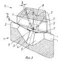
На фиг. 1 изображено базисное соединение структуры стыковочных поверхностей 1, 2, вырезанных из любой поверхности. Поверхности 3 кровли образуют внешний (положительный) выступ поверхности, а поверхности 4 основания - внутреннюю (отрицательную) выемку поверхности. К поверхностям кровли и основания примыкают грани 5 профилей, которые стыкуются друг с другом с симметричными углами и стыковочные края 6 которых содержат притупления 7. Оси кромок представляют собой направляющие оси 8, пересечения 9 которых образуют центр позиции фиксации.These preferred characteristics are shown as an example in the drawings, where:
In FIG. 1 shows the basic connection of the structure of the connecting
В данном случае могут "арретироваться" соответствующие, выполненные самым разнообразным образом поверхности, которые опираются с позиционированием о притупления 7. Их внешний выступ поверхности поддерживается при этом, однако, столь низким, что он не прилегает заранее к противолежащей поверхности 4 основания. In this case, corresponding surfaces made in a variety of ways can be "arrested", which are supported with positioning for blunting 7. Their external surface protrusion is maintained at the same time, however, so low that it does not fit in advance to the
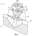
Фиг. 2 показывает стыковочную поверхность 2, которая отвечает по себе тем же условиям, которые изображены на фиг. 1, однако, с тем различием, что присутствует лишь поверхность 3 кровли и отсутствует поверхность основания. К граням 5 профилей могут примыкать любые другие поверхности, в настоящем случае - перпендикулярные боковые стенки 10. FIG. 2 shows a
На фиг. 3 обе стыковочных поверхности 1, 2 соединены в позиции фиксации. Взаимное опирание притуплений 7 стыковочных краев 6 обуславливает самоцентрирующее позиционирование в центре 9 позиции фиксации с вытекающими из этого, уже названными выше преимуществами. In FIG. 3, both connecting
Наряду с принципом конфигурации, который заключается в том, что в позициях 9 пересечения края 6 граней с их притуплением 7 проходят относительно друг друга центрально-симметрично, существует также возможность исполнения притуплений с постоянной или равномерно измененной шириной или лишь частичного исполнения и реализации их - при рассмотрении в поперечном сечении - слегка вогнутыми, выгнутыми или прямыми. В зависимости от поставленной задачи ширина b притуплений может иметь весьма различные величины по отношению к высоте соединения с целью достижения соответствия различным материалам или условиям контактирования. Along with the configuration principle, which consists in the fact that at
На фиг. 4 изображена высота h2 выемки, которая необходима для стыковочной поверхности 2 по меньшей мере для того, чтобы затем покинуть позицию фиксации в любом направлении вдоль направляющей оси 8 и достичь следующей определенной позиции в следующей позиции фиксации или перейти в расположенную между ними опорную позицию с опиранием поперечно направляющей оси.In FIG. 4 shows the height h 2 of the recess, which is necessary for the connecting
Эта высота подъема в случае соединения, содержащего стыковочную поверхность 2, зависит только от величины притупления краев кромок в сжатом состоянии и от их угла β краев. Если предположить при этом постоянные, плоские притупления 7, с шириной b1 = b2 = b, то в этом случае, например, при пересекающихся под углом 90о осях граней и угле α = 30о граней возникает угол β = 39,2о краев и весьма малая минимальная высота выемки h2 = b/tan β = 1,23b.In the case of a joint comprising a
С целью пояснения процесса фиг. 5 показывает выведенную из позиции 9 фиксации поверхности 1 и смещенную вдоль направляющей оси 8 в позицию 11 опирания поверхность 2. В данном случае она опирается о противолежащие грани 5 профиля поперечно направляющей оси. For the purpose of explaining the process of FIG. 5 shows the
Поверхности 3 кровли структуры 1, 2, 12 стыковочных поверхностей могут представлять собой части интегрированной, выполненной единым образом эталонной и/или опорной поверхности 13 для наложения любых элементов и в качестве базиса размера высоты при использовании комбинаций поверхностей элементов и стыковочных поверхностей. Эти единые поверхности могут иметь различную форму. Roof surfaces 3 of the structure of the connecting
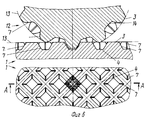
Фиг. 6 показывает в сечении через притупления 7 краев граней структуру 12 цилиндрической поверхности, состыкованную с плоской структурой 1 без изменения положенных в основу свойств, однако с существенным расширением практических возможностей использования. В данном случае также в качестве примера изображено исполнение поверхностей 3, 4, 14 кровли и основания с различными шириной и кривизной. Таким же образом форма граней 5 профилей или притуплений 7 может быть согласована с поставленной задачей и выполняться с различными углами в качестве плоской или имеющей ту же форму, например, форму эвольвенты поверхности. FIG. 6 shows in cross section through blunting 7 edges of the faces a
Независимо от формы кривизны поверхностей 3, 4 кровли и основания высоты h между ними и притупление 7 краев граней могут быть согласованы между собой таким образом, что до второй, выполненной аналогичным образом и состыкованной в позиции 9 фиксации без усилия нажима контрповерхности существует незначительное удаление h1 между обоюдными поверхностями кровли и основания.Regardless of the shape of curvature of the
Фиг. 7 показывает это в качестве сечения через обоюдно опирающиеся притупления. Под воздействием соответствующего давления прижима опирающиеся притупления претерпевают дальнейшую деформацию до тех пор, пока расстояние h1 не станет равным нулю и не будет обеспечено дополнительное опирание о те или иные поверхности кровли и основания. Это обусловливает то преимущество, что при следующем повышенном давлении прижима не возникает других деформаций притуплений. Эти деформации могут удерживаться в основном в упругом диапазоне, так что обеспечивается возможность в основном точно повторяемого позиционирования с приложением различных усилий прижима. Дополнительно при обоюдном прилегании тех или иных поверхностей кровли и основания, независимо от давления прижима, достигаются точно определяемые размеры, высота. Несмотря на увеличенную опорную поверхность обоюдное прилегание обеспечивается, кроме того, лишь для незначительной части общей поверхности - около 20-25%.FIG. 7 shows this as a section through mutually supported blunts. Under the influence of the corresponding pressure of the pressure, the underlying blunting undergoes further deformation until the distance h 1 becomes equal to zero and additional bearing on certain roof and base surfaces is ensured. This leads to the advantage that at the next increased pressure of the clamp no other deformation of blunting occurs. These deformations can be held mainly in the elastic range, so that it is possible mainly precisely repeatable positioning with the application of various pressure forces. Additionally, with the mutual adjoining of various roof and base surfaces, regardless of the pressure of the clamp, precisely defined dimensions and height are achieved. Despite the increased abutment surface, a mutual fit is provided, in addition, only for an insignificant part of the total surface - about 20-25%.
Описанный выше принцип конфигурации является целесообразным в том случае, если соединение стыковочных поверхностей перекрывает большие участки поверхности и если на ней должны быть позиционированы одна или несколько контрповерхностей без изменения обоюдных параметров точности размеров и повторения. The configuration principle described above is appropriate if the connection of the joining surfaces overlaps large portions of the surface and if one or more counter surfaces should be positioned on it without changing the mutual parameters of dimensional accuracy and repetition.
Фиг. 8 показывает пример для такого типа 15 поверхности. Он может стыковаться в основном идентичной контрповерхностью. Дополнительно при его использовании возможно, однако, опирание имеющих форму шара 16, усеченного конуса 17 или усеченной пирамиды 18 структур поверхностей в позиции фиксации о притуплении 7 и их направление вдоль направляющих осей. В частности, для такого типа опирающихся контрповерхностей может предусматриваться случай, когда они образуют необходимую ширину притуплений лишь под воздействием давления прижима. FIG. 8 shows an example for this type of
Представляется возможной также такая констрстыковочная структура 19, которая взаимно опирается только о несколько притуплений 7 нескольких участков 9 пересечения. Соответствующие поверхности профилей могут направляться также исключительно по граням 5 профилей и опираться о них. Фиг. 8 показывает также эталонные, направляющие или опорные поверхности 20 с однозначным приданием их участкам 9 пересечения, однако независимо от самого стыковочного соединения. Соединения может быть также оснащено отверстиями 21, которые характеризуются однозначным, симметричным отношением к участкам пересечения. It also seems possible such a reconstructing
Например, через эти отверстия 21 могут вводиться дополнительные приспособления, например, винты 22, подвижные опорные поверхности и подобные элементы, с помощью которых обеспечивается удержание самой стыковочной поверхности или прижим контрстыковочных поверхностей с силовым замыканием или вывод из участков фиксации. For example, additional devices can be introduced through these
Фиг. 9 показывает подвижную опорную поверхность 23, которая введена снизу через поверхность 4 основания в центре 9 соединения стыковочных поверхностей. Она служит для подъема контрстыковочной поверхности из позиции фиксации на необходимую для осуществления дальнейшего движения высоту h2 подъема. Если опорная поверхность 23 остается в этой приподнятой позиции, то в этом случае она обеспечивает защиту от повторной фиксации, если - как видно, например, из изображенного на фиг. 5 - контрстыковочные поверхности 2 перемещаются через этот участок фиксации.FIG. 9 shows a
В случае соответствующих изобретению стыковочных поверхностей b на участках 9 фиксации перекрещивающихся предпочтительно по две направляющих оси 8 под углом γ = 90о. Могут перекрещиваться также и три направляющих оси с возможностью выбора различных углов пересечения.In the case of the inventive docking surfaces b on the
Направляющие оси могут проходить прямолинейно или с искривлением, так что на нескольких участках перекрещивания все соответствующие направляющие оси могут располагаться как параллельно друг другу (см. фиг. 8), так и центрально-симметрично. The guide axes can be straight or curved, so that in several sections of the intersection all the corresponding guide axes can be located parallel to each other (see Fig. 8), and centrally symmetrical.
Фиг. 10 показывает центрально-симметричную конструкцию в трех вариантах, при которой оси проходят, с одной стороны - к центру 24 и, с другой стороны - концентрически вокруг этого центра. FIG. 10 shows a centrally symmetrical structure in three versions, in which the axes extend, on the one hand, to the
На фиг. 10 в правой нижней части в направлении к центру 24 сужается, например, только поверхность 3 кровли. Ширина поверхностей 4 основания и всех граней 5 профилей, а также высота соединения остаются неизменными. В левой нижней части фиг. 9 поверхности 3, 4 основания, грани 25 профилей и высота h структуры сужаются в направлении центра. Концентрические грани профилей имеют в зависимости от удаления от центра постоянную ширину. In FIG. 10 in the lower right part towards the
Соединение стыковочных поверхностей по фиг. 10, правая и левая нижняя части, могут стыковаться с равнозначными контрповерхностями, которые лишь смещены по радиусу, применительно к функции направления или функции фиксации. The connection of the connecting surfaces of FIG. 10, the lower right and left parts can be joined with equivalent counter-surfaces that are only radially displaced with respect to the direction function or the fix function.
В верхней центральной части фиг. 10 изображено соединение, аналогичное изображенному в правой нижней части фиг. 10, однако с тем отличием, что грани 26 профилей проходят вдоль концентрических направляющих осей 8 с изменяющейся шириной, в результате чего в этой области поверхности 4 основания также могут проходить с различной шириной и высотой. Форма кромок такого типа облегчает боковое введение стыковочных поверхностей в позицию фиксации. In the upper central part of FIG. 10 shows a connection similar to that shown in the lower right part of FIG. 10, however, with the difference that the
Например, для поверхностей этого типа и в случае постановки задачи применительно к направленному движению поверхностей относительно друг друга между поверхностями вводятся предпочтительно дополнительные среды скольжения. For example, for surfaces of this type and in the case of setting the problem in relation to the directed movement of the surfaces relative to each other, preferably additional sliding media are introduced between the surfaces.
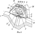
Фиг. 11 показывает в качестве примера два следующих принципа конфигурации для тела, имеющего соединение стыковочных поверхностей. Опирающаяся снизу поверхность 1 представляет собой простую тонкостенную поверхность или полое тело 27, которое может быть состыковано с аналогичной тонкостенной поверхностью. FIG. 11 shows, by way of example, the following two configuration principles for a body having a connection of mating surfaces. The bottom-supported
Введенная сверху в позицию фиксации контрповерхность характеризуется, напротив, единой внешней поверхностью отдельного элемента полого тела. Грани 5 профилей и обоюдные поверхности 3 кровли могут иметь в данном случае сквозные отверстия, в результате чего возникает пространственное соединение 28, изображенное посредством имеющих форму стержней поверхностей 29 вдоль краев 30 поверхностей и притуплений 7. Пространственное соединение составлено предпочтительно из отдельных элементов этих имеющих стержневую форму. The counter-surface introduced from above into the fixation position is characterized, on the contrary, by a single external surface of an individual element of the hollow body. The faces 5 of the profiles and the
Следующие соединения стыковочных поверхностей, например, в расположенном внизу полом теле 27, могут также дополнительно присоединяться сверху, так что отдельное среднее тело 28 принимает на себя функцию связи. Для взаимного крепления этих полых тел или тонкостенных элементов они могут удерживаться в области опирающихся притуплений 7 краев граней с помощью винтов, отвердевающей охватывающей среды 31 или т.п. The following joints of the mating surfaces, for example, in the
Если ширина притуплений 7 и высота структуры согласованы между собой таким образом, что друг о друга опираются как притупления, так и те или иные поверхности 3, 4 кровли и основания, то в этом случае крепление новых тел может осуществляться также и в области этих поверхностей. If the width of the
Claims (6)
Applications Claiming Priority (3)
| Application Number | Priority Date | Filing Date | Title |
|---|---|---|---|
| EP87111299.1 | 1987-08-05 | ||
| EP87111299A EP0304498B1 (en) | 1987-08-05 | 1987-08-05 | Assembling surface structure for guiding and/or positioning of construction elements |
| PCT/EP1988/000680 WO1989001079A1 (en) | 1987-08-05 | 1988-07-27 | Joint surface structure for guiding and positioning constructional elements |
Publications (1)
| Publication Number | Publication Date |
|---|---|
| RU2019653C1 true RU2019653C1 (en) | 1994-09-15 |
Family
ID=8197184
Family Applications (1)
| Application Number | Title | Priority Date | Filing Date |
|---|---|---|---|
| SU894613933A RU2019653C1 (en) | 1987-08-05 | 1989-04-05 | Butt joint of member surfaces |
Country Status (10)
| Country | Link |
|---|---|
| EP (1) | EP0304498B1 (en) |
| JP (1) | JP2809660B2 (en) |
| KR (1) | KR0146705B1 (en) |
| CN (1) | CN1019218B (en) |
| AT (1) | ATE90132T1 (en) |
| CA (1) | CA1340394C (en) |
| DD (1) | DD282042A5 (en) |
| DE (1) | DE3786082D1 (en) |
| RU (1) | RU2019653C1 (en) |
| WO (1) | WO1989001079A1 (en) |
Families Citing this family (5)
| Publication number | Priority date | Publication date | Assignee | Title |
|---|---|---|---|---|
| DE4139672A1 (en) * | 1991-12-02 | 1993-06-03 | Joerg Wiemers | ELEMENT SYSTEM, ESPECIALLY FOR CLAMPING WORKPIECES |
| DE4142362A1 (en) * | 1991-12-20 | 1993-07-08 | Wolfgang Fischer | DEVICE FOR CLAMPING AN OBJECT ON A CARRIER, IN PARTICULAR FOR MACHINE TOOLS |
| DE20318846U1 (en) * | 2003-12-02 | 2004-04-08 | Horst Witte Entwicklungs- Und Vertriebs-Kg | System for building devices for receiving workpieces and connecting element for use in such a system |
| CN108547845A (en) * | 2018-06-28 | 2018-09-18 | 同济大学 | A kind of deformation retract equipped with chamfering is from replying split type unilateral bolt fastener |
| CN114960967B (en) * | 2022-05-26 | 2023-08-11 | 中建八局总承包建设有限公司 | Resin screw rod connecting device |
Family Cites Families (6)
| Publication number | Priority date | Publication date | Assignee | Title |
|---|---|---|---|---|
| FR1007772A (en) * | 1948-03-30 | 1952-05-09 | Building stone and masonry made with this stone | |
| FR1400719A (en) * | 1963-06-05 | 1965-05-28 | Lurgan Boxmaking Company Ltd | Development of egg trays |
| DE2225302A1 (en) * | 1971-05-26 | 1972-12-07 | Blagojevitz, Duschan, Slankamen, Potes-Oduschevci (Jugoslawien) | Walls without connecting material |
| DE2537146C3 (en) * | 1975-08-21 | 1980-05-14 | Hubert Dipl.-Ing. 5820 Gevelsberg Bald | Unit of two components to be positioned in a relative position |
| ES8703099A1 (en) * | 1984-11-01 | 1987-02-16 | Buechler B Set Ag | Retaining device for an object. |
| CH667408A5 (en) * | 1985-05-20 | 1988-10-14 | Istema Ind Elektrotechnik Und | KIT FOR ASSEMBLING PARTS AND USE THE SAME. |
-
1987
- 1987-08-05 DE DE8787111299T patent/DE3786082D1/en not_active Expired - Fee Related
- 1987-08-05 EP EP87111299A patent/EP0304498B1/en not_active Expired - Lifetime
- 1987-08-05 AT AT87111299T patent/ATE90132T1/en not_active IP Right Cessation
-
1988
- 1988-07-27 JP JP63506203A patent/JP2809660B2/en not_active Expired - Fee Related
- 1988-07-27 WO PCT/EP1988/000680 patent/WO1989001079A1/en unknown
- 1988-07-27 KR KR1019890700545A patent/KR0146705B1/en not_active IP Right Cessation
- 1988-07-30 CN CN88104760A patent/CN1019218B/en not_active Expired
- 1988-08-02 DD DD88318583A patent/DD282042A5/en not_active IP Right Cessation
- 1988-08-04 CA CA000573870A patent/CA1340394C/en not_active Expired - Fee Related
-
1989
- 1989-04-05 RU SU894613933A patent/RU2019653C1/en active
Non-Patent Citations (2)
| Title |
|---|
| 1. Патент ФРГ N 2537146, кл. F 16B 5/02, 1977. * |
| 2. Патент ФРГ N 3435119, кл. B 23Q 3/00, 1985. * |
Also Published As
| Publication number | Publication date |
|---|---|
| CN1019218B (en) | 1992-11-25 |
| WO1989001079A1 (en) | 1989-02-09 |
| EP0304498A1 (en) | 1989-03-01 |
| DD282042A5 (en) | 1990-08-29 |
| CN1032205A (en) | 1989-04-05 |
| JPH02501078A (en) | 1990-04-12 |
| EP0304498B1 (en) | 1993-06-02 |
| KR0146705B1 (en) | 1998-09-15 |
| DE3786082D1 (en) | 1993-07-08 |
| CA1340394C (en) | 1999-02-16 |
| ATE90132T1 (en) | 1993-06-15 |
| KR890701853A (en) | 1989-12-22 |
| JP2809660B2 (en) | 1998-10-15 |
Similar Documents
| Publication | Publication Date | Title |
|---|---|---|
| US6193430B1 (en) | Quasi-kinematic coupling and method for use in assembling and locating mechanical components and the like | |
| DE4307342C2 (en) | Device for the position-defined clamping of a workpiece at the workplace of a processing machine | |
| US4065220A (en) | Structural system connection | |
| US6231416B1 (en) | Genderless construction system | |
| US3528691A (en) | Keyway lock | |
| US5786002A (en) | Guide block assembly for aligning bore forming pins during molding of multi-fiber optical connector ferrules | |
| RU2019653C1 (en) | Butt joint of member surfaces | |
| JPH06304344A (en) | Assembling blocks | |
| GB1559656A (en) | Composite wall structure of bricks | |
| JPS63102856A (en) | Device for determining relative position to second body of first body with high precision in reproducible manner | |
| CN110062645B (en) | Building block and building block combination | |
| SU1119613A3 (en) | Transmission chain for bevel disk transmission | |
| JPH0759607A (en) | Opposite interlocking zipper member | |
| US5046707A (en) | Spherical positioning pin | |
| US5140660A (en) | Optical connector ferrule | |
| US20150043872A1 (en) | Ferrule with protruding fibers | |
| US4580922A (en) | Vertex fittings derived from a master fitting | |
| GB2118318A (en) | Connector for light waveguides | |
| EP0147444B1 (en) | Device for positioning the end of an optical fibre in a sleeve | |
| US4184669A (en) | Operation on workpieces | |
| JPH0218442B2 (en) | ||
| CA2101425A1 (en) | Modular system, in particular for the clamping of work pieces | |
| DE3831736A1 (en) | Positioning device and its use | |
| KR960021082A (en) | Block assembly | |
| JPH05503588A (en) | fiber optic interconnection equipment |