RU201848U1 - COMBUSTION CHAMBER OF A GAS TURBINE ENGINE WITH AN ACTIVE COOLING ZONE - Google Patents
COMBUSTION CHAMBER OF A GAS TURBINE ENGINE WITH AN ACTIVE COOLING ZONE Download PDFInfo
- Publication number
- RU201848U1 RU201848U1 RU2020127165U RU2020127165U RU201848U1 RU 201848 U1 RU201848 U1 RU 201848U1 RU 2020127165 U RU2020127165 U RU 2020127165U RU 2020127165 U RU2020127165 U RU 2020127165U RU 201848 U1 RU201848 U1 RU 201848U1
- Authority
- RU
- Russia
- Prior art keywords
- damping
- gas turbine
- combustion chamber
- turbine engine
- increase
- Prior art date
Links
Images
Classifications
-
- F—MECHANICAL ENGINEERING; LIGHTING; HEATING; WEAPONS; BLASTING
- F23—COMBUSTION APPARATUS; COMBUSTION PROCESSES
- F23R—GENERATING COMBUSTION PRODUCTS OF HIGH PRESSURE OR HIGH VELOCITY, e.g. GAS-TURBINE COMBUSTION CHAMBERS
- F23R3/00—Continuous combustion chambers using liquid or gaseous fuel
- F23R3/02—Continuous combustion chambers using liquid or gaseous fuel characterised by the air-flow or gas-flow configuration
- F23R3/04—Air inlet arrangements
- F23R3/06—Arrangement of apertures along the flame tube
Landscapes
- Engineering & Computer Science (AREA)
- Chemical & Material Sciences (AREA)
- Combustion & Propulsion (AREA)
- Mechanical Engineering (AREA)
- General Engineering & Computer Science (AREA)
- Turbine Rotor Nozzle Sealing (AREA)
Abstract
Полезная модель относится к камерам сгорания газотурбинных двигателей, в частности к жаровым трубам камер сгорания и установок, и может быть использована в авиационной, судовой, а также в энергетической отрасли. Устройство состоит из корпуса, в котором расположена жаровая труба, образуя кольцевой канал. Жаровая труба имеет, по меньшей мере, один пояс подвода охладителя, содержащий выполненные в обечайке щели в форме конфузора для подвода охладителя, расположенные на аэродинамическом выступе, между поясами подвода охладителя выполнены демпфирующие поверхности, состоящие из полусферических демпфирующих полостей, взаимодействующих с потоком через перфорационные отверстия, выполненные на внутренней стенке демпфирующей поверхности, полусферические демпфирующие полости образуют полусферические выступы на внешней стенке демпфирующей поверхности, щели в форме конфузора для подвода охладителя образуют ребра в окружном направлении. Технический результат - повышение эффективности тепловой защиты камеры сгорания газотурбинного двигателя, повышение теплоотдачи камеры сгорания газотурбинного двигателя, повышение КПД двигателя, увеличение надежности и ресурса камеры сгорания.The utility model relates to combustion chambers of gas turbine engines, in particular to the flame tubes of combustion chambers and installations, and can be used in the aviation, marine and energy industries. The device consists of a body in which a flame tube is located, forming an annular channel. The flame tube has at least one coolant supply belt, containing slots in the shell in the form of a confuser for coolant supply, located on the aerodynamic protrusion, damping surfaces are made between the coolant supply belts, consisting of hemispherical damping cavities interacting with the flow through perforations , made on the inner wall of the damping surface, hemispherical damping cavities form hemispherical protrusions on the outer wall of the damping surface, the slots in the form of a confuser for supplying the coolant form ribs in the circumferential direction. The technical result is an increase in the efficiency of thermal protection of the combustion chamber of a gas turbine engine, an increase in heat transfer from the combustion chamber of a gas turbine engine, an increase in the efficiency of the engine, an increase in the reliability and resource of the combustion chamber.
Description
Полезная модель относится к газотурбинным двигателям, в частности к жаровым трубам камер сгорания, и может быть использована в авиационной, судовой, а также в энергетической отрасли.The utility model relates to gas turbine engines, in particular to the flame tubes of combustion chambers, and can be used in the aviation, marine, and energy industries.
Наиболее близким устройством того же назначения к заявленной полезной модели по совокупности признаков является жаровая труба камеры сгорания газотурбинного двигателя с демпфирующими полостями, содержащая жаровую трубу, расположенную внутри корпуса с образованием кольцевого канала. Жаровая труба имеет, по меньшей мере, один пояс подвода охладителя, содержащий выполненные в обечайке дозирующие отверстия и пазы, сообщенные через отверстия с кольцевым каналом, отверстия и пазы расположены на обечайке в окружном направлении, причем пазы расположены таким образом, что при образовании пазов известным методом электроэрозии - вытравливанием металла электродом - между соседними пазами образуются ребра, толщина которых равна расстоянию d между пазами в окружном направлении, на поверхности обечайки со стороны горячего газа, между соседними поясами подвода охладителя в окружном направлении расположены демпфирующие полости, взаимодействующие с потоком посредством перфорационных отверстий, выполненных на перфорированной пластине, плотно соединенной с обечайкой [1].The closest device for the same purpose to the claimed utility model in terms of the totality of features is a flame tube of the combustion chamber of a gas turbine engine with damping cavities, containing a flame tube located inside the housing to form an annular channel. The flame tube has at least one coolant supply belt containing metering holes and grooves made in the shell connected through the holes with the annular channel, the holes and grooves are located on the shell in the circumferential direction, and the grooves are arranged in such a way that when the grooves are formed, the known by electroerosion - metal etching with an electrode - ribs are formed between adjacent grooves, the thickness of which is equal to the distance d between the grooves in the circumferential direction, on the shell surface from the side of the hot gas, damping cavities are located between adjacent coolant supply belts in the circumferential direction, interacting with the flow through perforations made on a perforated plate, tightly connected to the shell [1].
К причинам, препятствующим достижению указанного ниже технического результата при использовании известного устройства, принятого за прототип, относится то, что дозирующие отверстия и пазы, выполненные в обечайке, имеют ряд недостатков проявляющихся в сложности их выполнения и необходимости утолщения стенки в форме «ступени», что вызывает турбулизацию охлаждаемого потока воздуха и снижение эффективности тепловой защиты поверхности. Кроме того демпфирующие полости цилиндрической формы имеют ряд недостатков, проявляющихся в необходимости утолщения стенки для расположения в ней цилиндрических демпфирующих полостей, что вызывает дополнительное температурное напряжение металла и приводит к снижению эксплуатационного ресурса, также демпфирующие полости цилиндрической формы не эффективно гасят турбулентные пульсации давления (и скорости) в пограничном слое на внутренней стенке обечайки. Форма цилиндрических демпфирующих полостей не позволяет образовать эффективные турбулизаторы на внешней стенке обечайки.The reasons that impede the achievement of the technical result indicated below when using a known device, taken as a prototype, is that the metering holes and grooves made in the shell have a number of disadvantages manifested in the complexity of their implementation and the need to thicken the wall in the form of a "step" that causes turbulization of the cooled air flow and a decrease in the effectiveness of thermal protection of the surface. In addition, the damping cavities of a cylindrical shape have a number of disadvantages, manifested in the need to thicken the wall for the location of cylindrical damping cavities in it, which causes additional temperature stress in the metal and leads to a decrease in the service life; ) in the boundary layer on the inner wall of the shell. The shape of the cylindrical damping cavities does not allow the formation of effective turbulators on the outer wall of the shell.
Технической проблемой, на решение которой направлена полезная модель, является разработка камеры сгорания газотурбинного двигателя с активной зоной охлаждения.The technical problem to be solved by the utility model is the development of a combustion chamber for a gas turbine engine with an active cooling zone.
Сущность полезной модели заключается в применении щелей в форме конфузора для подвода охладителя, располагаемых на обечайке в окружном направлении, причем щели расположены таким образом, что между ними образуются ребра, толщина которых равна половине ширины щели; демпфирующей поверхности в обечайке камеры сгорания газотурбинного двигателя, располагаемой между соседними поясами подвода охладителя в окружном направлении.The essence of the utility model consists in using slots in the form of a confuser for supplying a coolant, located on the shell in the circumferential direction, and the slots are located in such a way that ribs are formed between them, the thickness of which is equal to half the width of the slot; damping surface in the shell of the combustion chamber of the gas turbine engine, located between adjacent chords of the coolant supply in the circumferential direction.
Технический результат - повышение эффективности тепловой защиты камеры сгорания газотурбинного двигателя, повышение теплоотдачи камеры сгорания газотурбинного двигателя, повышение КПД двигателя, увеличение надежности и ресурса камеры сгорания.The technical result is an increase in the efficiency of thermal protection of the combustion chamber of a gas turbine engine, an increase in the heat transfer of the combustion chamber of a gas turbine engine, an increase in the efficiency of the engine, an increase in the reliability and resource of the combustion chamber.
Указанный технический результат при осуществлении полезной модели достигается тем, что камера сгорания газотурбинного двигателя с активной зоной охлаждения содержит жаровую трубу, расположенную внутри корпуса с образованием кольцевого канала, жаровая труба имеет, по меньшей мере, один пояс подвода охладителя, расположенный в окружном направлении.The specified technical result in the implementation of the utility model is achieved in that the combustion chamber of a gas turbine engine with an active cooling zone contains a flame tube located inside the housing with the formation of an annular channel, the flame tube has at least one coolant supply belt located in the circumferential direction.
Особенность заключается в том, что в предлагаемой полезной модели, в обечайке, на аэродинамическом выступе, расположены щели в форме конфузора для подвода охладителя, образующие ребра равные половине ширины щели в окружном направлении. Также между соседними поясами подвода охладителя в окружном направлении расположены демпфирующие поверхности.The peculiarity lies in the fact that in the proposed utility model, in the shell, on the aerodynamic protrusion, there are slots in the form of a confuser for supplying the coolant, forming ribs equal to half the width of the slot in the circumferential direction. Also, damping surfaces are located between adjacent chords of the coolant supply in the circumferential direction.
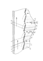
Полезная модель поясняется чертежом, показывающим схему его реализации.The utility model is illustrated by a drawing showing a diagram of its implementation.
Камера сгорания газотурбинного двигателя с активной зоной охлаждения содержит: корпус 1, в котором расположена жаровая труба 2, образуя кольцевой канал 3. Жаровая труба 2 имеет, по меньшей мере, один пояс подвода охладителя расположенный в окружном направлении, содержащий выполненные в обечайке 4 щели в форме конфузора для подвода охладителя 5, расположенные на аэродинамическом выступе 6. Между поясами подвода охладителя выполнены в окружном направлении демпфирующие поверхности 7 состоящие из полусферических демпфирующих полостей 8, взаимодействующих с потоком через перфорационные отверстия 9, выполненные на внутренней стенке 10 демпфирующей поверхности 7. Полусферические демпфирующие полости 8 образуют полусферические выступы 11 на внешней стенке 12 демпфирующей поверхности 7. Щели в форме конфузора для подвода охладителя 5 образуют ребра 13 равные половине ширины щели, расположенные в окружном направлении.The combustion chamber of a gas turbine engine with an active cooling zone comprises: a
Устройство работает следующим образом.The device works as follows.
Охлаждающий воздух, движущийся вдоль кольцевого канала 3, обтекает обечайку 4, в которой расположена демпфирующая поверхность 7 между соседними поясами подвода охладителя, и турбулизируется за счет обтекания полусферических выступов 11, выполненных на внешней стенке 12 демпфирующей поверхности 7. Турбулизация охлаждающего воздуха увеличивает теплосъем с демпфирующей поверхности 7, что приводит к повышению эффективности тепловой защиты жаровой трубы 2, кроме-того полусферические выступы 11 увеличивают площадь теплообмена и способствуют увеличению теплосъема с демпфирующей поверхности 7. Турбулизированный охлаждающий воздух натекает на аэродинамический выступ 6, который в свою очередь снижает интенсивность турбулентных пульсаций и ламинаризирует пограничный слой. Далее часть охлаждающего воздуха поступает на внутреннюю стенку 10 демпфирующей поверхности 7, через щели в форме конфузора для подвода охладителя 5, вследствие чего происходит выравнивание потока охлаждающего воздуха, который затем выходит вдоль обечайки 4, со стороны потока горячего газа, в которой расположена демпфирующая поверхность 7, взаимодействующая с потоком охлаждающего воздуха через перфорационные отверстия 9, расположенные на внутренней стенке демпфирующей поверхности 7, причем на одну полусферическую демпфирующую полость 8 приходится два перфорационных отверстия 9. В результате обтекания внутренней стенки 10 демпфирующей поверхности 7, пристеночная завеса (защитная пелена охлаждающего воздуха) образует эффективную конвективную тепловую защиту в следствии ламинаризации потока за счет перетекания некоторой массы газа m в полусферическую демпфирующую полость 8 и обратно. Из-за пружинящего эффекта полусферической демпфирующей полости 8 турбулентные пульсации будут ослабевать, что приведет к уменьшению сопротивления трения потока на внутренней стенке 10 демпфирующей поверхности 7 и затягиванию защитной пелены охлаждающего воздуха на поверхности обечайки 4 со стороны горячего газа, между соседними поясами подвода охладителя в окружном направлении, кроме того за счет перетекания некоторой массы охлаждающего воздуха m в полусферические демпфирующие полости 8 и обратно, образуется эффективный теплосъем с обечайки 4. Также через металл ребер 13 (перемычек) обеспечивается эффективный съем тепла посредством теплопроводности с внутренней поверхности жаровой трубы 2, обращенной к потоку горячего газа. Таким образом, пристеночная завеса образует эффективную конвективную тепловую защиту внутренней поверхности обечайки 4 на всей поверхности между поясами подвода охладителя по направлению к выходному сечению жаровой трубы 2.The cooling air moving along the
Литература.Literature.
1. Патент РФ №173450, опубл. 28.08.2017.1. RF patent No. 173450, publ. 28.08.2017.
Claims (1)
Priority Applications (1)
| Application Number | Priority Date | Filing Date | Title |
|---|---|---|---|
| RU2020127165U RU201848U1 (en) | 2020-08-12 | 2020-08-12 | COMBUSTION CHAMBER OF A GAS TURBINE ENGINE WITH AN ACTIVE COOLING ZONE |
Applications Claiming Priority (1)
| Application Number | Priority Date | Filing Date | Title |
|---|---|---|---|
| RU2020127165U RU201848U1 (en) | 2020-08-12 | 2020-08-12 | COMBUSTION CHAMBER OF A GAS TURBINE ENGINE WITH AN ACTIVE COOLING ZONE |
Publications (1)
| Publication Number | Publication Date |
|---|---|
| RU201848U1 true RU201848U1 (en) | 2021-01-15 |
Family
ID=74183578
Family Applications (1)
| Application Number | Title | Priority Date | Filing Date |
|---|---|---|---|
| RU2020127165U RU201848U1 (en) | 2020-08-12 | 2020-08-12 | COMBUSTION CHAMBER OF A GAS TURBINE ENGINE WITH AN ACTIVE COOLING ZONE |
Country Status (1)
| Country | Link |
|---|---|
| RU (1) | RU201848U1 (en) |
Cited By (1)
| Publication number | Priority date | Publication date | Assignee | Title |
|---|---|---|---|---|
| RU2803149C1 (en) * | 2023-02-09 | 2023-09-07 | Федеральное государственное казенное военное образовательное учреждение высшего образования "Военный учебно-научный центр Военно-воздушных сил "Военно-воздушная академия имени профессора Н.Е. Жуковского и Ю.А. Гагарина" (г. Воронеж) Министерства обороны Российской Федерации | Flame tube of combustion chamber |
Citations (6)
| Publication number | Priority date | Publication date | Assignee | Title |
|---|---|---|---|---|
| US3706203A (en) * | 1970-10-30 | 1972-12-19 | United Aircraft Corp | Wall structure for a gas turbine engine |
| EP0019417B1 (en) * | 1979-05-18 | 1983-01-12 | Rolls-Royce Plc | Combustion apparatus for gas turbine engines |
| RU2260748C2 (en) * | 2003-12-02 | 2005-09-20 | Открытое акционерное общество "Авиадвигатель" | Combustion chamber for gas-turbine engine |
| RU76701U1 (en) * | 2008-06-03 | 2008-09-27 | Федеральное государственное унитарное предприятие "Московское машиностроительное производственное предприятие "САЛЮТ" (ФГУП "ММПП "САЛЮТ") | FIRE PIPE OF THE COMBUSTION CHAMBER OF A GAS TURBINE ENGINE |
| RU2354889C2 (en) * | 2006-03-30 | 2009-05-10 | Снекма | Annular combustion chamber of gas-turbine engine, gas turbine chamber, element of side wall designed to form combustion chamber |
| RU173450U1 (en) * | 2016-11-15 | 2017-08-28 | федеральное государственное бюджетное образовательное учреждение высшего образования "Ульяновский государственный технический университет" | HEAT PIPE OF THE COMBUSTION CHAMBER OF A GAS-TURBINE ENGINE WITH DAMPING CAVES |
-
2020
- 2020-08-12 RU RU2020127165U patent/RU201848U1/en not_active IP Right Cessation
Patent Citations (6)
| Publication number | Priority date | Publication date | Assignee | Title |
|---|---|---|---|---|
| US3706203A (en) * | 1970-10-30 | 1972-12-19 | United Aircraft Corp | Wall structure for a gas turbine engine |
| EP0019417B1 (en) * | 1979-05-18 | 1983-01-12 | Rolls-Royce Plc | Combustion apparatus for gas turbine engines |
| RU2260748C2 (en) * | 2003-12-02 | 2005-09-20 | Открытое акционерное общество "Авиадвигатель" | Combustion chamber for gas-turbine engine |
| RU2354889C2 (en) * | 2006-03-30 | 2009-05-10 | Снекма | Annular combustion chamber of gas-turbine engine, gas turbine chamber, element of side wall designed to form combustion chamber |
| RU76701U1 (en) * | 2008-06-03 | 2008-09-27 | Федеральное государственное унитарное предприятие "Московское машиностроительное производственное предприятие "САЛЮТ" (ФГУП "ММПП "САЛЮТ") | FIRE PIPE OF THE COMBUSTION CHAMBER OF A GAS TURBINE ENGINE |
| RU173450U1 (en) * | 2016-11-15 | 2017-08-28 | федеральное государственное бюджетное образовательное учреждение высшего образования "Ульяновский государственный технический университет" | HEAT PIPE OF THE COMBUSTION CHAMBER OF A GAS-TURBINE ENGINE WITH DAMPING CAVES |
Cited By (1)
| Publication number | Priority date | Publication date | Assignee | Title |
|---|---|---|---|---|
| RU2803149C1 (en) * | 2023-02-09 | 2023-09-07 | Федеральное государственное казенное военное образовательное учреждение высшего образования "Военный учебно-научный центр Военно-воздушных сил "Военно-воздушная академия имени профессора Н.Е. Жуковского и Ю.А. Гагарина" (г. Воронеж) Министерства обороны Российской Федерации | Flame tube of combustion chamber |
Similar Documents
| Publication | Publication Date | Title |
|---|---|---|
| JP4575532B2 (en) | Hot wall with impingement baffle with dimples | |
| US11085644B2 (en) | Internally cooled dilution hole bosses for gas turbine engine combustors | |
| CA2892096C (en) | Combustor heat shield | |
| US7219498B2 (en) | Waffled impingement effusion method | |
| US20150345789A1 (en) | Combustor heat shield | |
| CN113464283B (en) | Compound initiative cooling structure of rotatory detonation engine and rotatory detonation engine | |
| RU2011136856A (en) | THERMOELECTRIC GAS TURBINE GENERATOR | |
| CN113513371A (en) | Double-wall cooling blade, turbine blade using same and gas turbine | |
| KR100789037B1 (en) | Improved heat exchanger for power generation equipment | |
| RU201848U1 (en) | COMBUSTION CHAMBER OF A GAS TURBINE ENGINE WITH AN ACTIVE COOLING ZONE | |
| CN104359126A (en) | Staggered cooling structure of flame tube in combustion chamber of gas turbine | |
| RU207006U1 (en) | Double-walled flame tube of a high-temperature continuous combustion chamber | |
| RU173450U1 (en) | HEAT PIPE OF THE COMBUSTION CHAMBER OF A GAS-TURBINE ENGINE WITH DAMPING CAVES | |
| WO2022227582A1 (en) | Combustion chamber structure having heat exchanger | |
| EP3591295B1 (en) | Combustor for a gas turbine engine having a combustion chamber and a heatshield with cooling turbulators | |
| CN204254678U (en) | A kind of alternating expression cooling structure of gas-turbine combustion chamber burner inner liner | |
| CN216617632U (en) | An engine exhaust waste heat energy thermoelectric power generation device with silencing function | |
| JPH0648095B2 (en) | Liner cooling structure for gas turbine combustors, etc. | |
| RU76701U1 (en) | FIRE PIPE OF THE COMBUSTION CHAMBER OF A GAS TURBINE ENGINE | |
| RU2260748C2 (en) | Combustion chamber for gas-turbine engine | |
| RU225855U1 (en) | Nozzle blade of a gas turbine engine with vibration damping system | |
| EP3567332A1 (en) | Swirling feed tube for heat exchanger | |
| SU994895A1 (en) | Heat exchanger | |
| RU2200926C2 (en) | Heat-exchange surface | |
| RU163785U1 (en) | GAS-TURBINE ENGINE TURBINE NOZZLE DEVICE |
Legal Events
| Date | Code | Title | Description |
|---|---|---|---|
| MM9K | Utility model has become invalid (non-payment of fees) |
Effective date: 20210131 |