RU201788U1 - SUBMERSIBLE PUMP UNIT DRIVE WITH A HEAT EXCHANGER - Google Patents
SUBMERSIBLE PUMP UNIT DRIVE WITH A HEAT EXCHANGER Download PDFInfo
- Publication number
- RU201788U1 RU201788U1 RU2020132704U RU2020132704U RU201788U1 RU 201788 U1 RU201788 U1 RU 201788U1 RU 2020132704 U RU2020132704 U RU 2020132704U RU 2020132704 U RU2020132704 U RU 2020132704U RU 201788 U1 RU201788 U1 RU 201788U1
- Authority
- RU
- Russia
- Prior art keywords
- heat exchanger
- oil
- electric motor
- channel
- compensator
- Prior art date
Links
Images
Classifications
-
- F—MECHANICAL ENGINEERING; LIGHTING; HEATING; WEAPONS; BLASTING
- F04—POSITIVE - DISPLACEMENT MACHINES FOR LIQUIDS; PUMPS FOR LIQUIDS OR ELASTIC FLUIDS
- F04D—NON-POSITIVE-DISPLACEMENT PUMPS
- F04D13/00—Pumping installations or systems
- F04D13/02—Units comprising pumps and their driving means
- F04D13/06—Units comprising pumps and their driving means the pump being electrically driven
- F04D13/08—Units comprising pumps and their driving means the pump being electrically driven for submerged use
- F04D13/10—Units comprising pumps and their driving means the pump being electrically driven for submerged use adapted for use in mining bore holes
-
- F—MECHANICAL ENGINEERING; LIGHTING; HEATING; WEAPONS; BLASTING
- F04—POSITIVE - DISPLACEMENT MACHINES FOR LIQUIDS; PUMPS FOR LIQUIDS OR ELASTIC FLUIDS
- F04D—NON-POSITIVE-DISPLACEMENT PUMPS
- F04D29/00—Details, component parts, or accessories
- F04D29/58—Cooling; Heating; Diminishing heat transfer
- F04D29/5806—Cooling the drive system
-
- F—MECHANICAL ENGINEERING; LIGHTING; HEATING; WEAPONS; BLASTING
- F04—POSITIVE - DISPLACEMENT MACHINES FOR LIQUIDS; PUMPS FOR LIQUIDS OR ELASTIC FLUIDS
- F04D—NON-POSITIVE-DISPLACEMENT PUMPS
- F04D29/00—Details, component parts, or accessories
- F04D29/58—Cooling; Heating; Diminishing heat transfer
- F04D29/586—Cooling; Heating; Diminishing heat transfer specially adapted for liquid pumps
- F04D29/5866—Cooling at last part of the working fluid in a heat exchanger
-
- H—ELECTRICITY
- H02—GENERATION; CONVERSION OR DISTRIBUTION OF ELECTRIC POWER
- H02K—DYNAMO-ELECTRIC MACHINES
- H02K9/00—Arrangements for cooling or ventilating
- H02K9/19—Arrangements for cooling or ventilating for machines with closed casing and closed-circuit cooling using a liquid cooling medium, e.g. oil
Abstract
Устройство относится к нефтяному машиностроению, а именно к оборудованию для нефтедобычи, и может быть использовано в скважинных многоступенчатых центробежных насосах с высокооборотными приводами, построенными на основе маслонаполненного электродвигателя с теплообменником, гидрозащитой и компенсатором.Привод погружной насосной установки с теплообменником содержит корпус, маслозаполненный электродвигатель, присоединенный к нему теплообменник, расположенный ниже электродвигателя, компенсатор, установленный в теплообменнике и гидравлически связанный каналом для масла с маслозаполненной полостью электродвигателя. Привод имеет каналы, обеспечивающие циркуляцию масла в приводе для теплообмена между маслом и скважинной жидкостью. Внутри теплообменника выполнен сквозной канал теплообменника для протока скважинной жидкости. Компенсатор имеет диафрагму из эластомерного материала, которая размещена в цилиндрическом кожухе с возможностью примыкания внешней боковой поверхности диафрагмы к соответствующей внутренней боковой поверхности кожуха. Сквозной канал теплообменника для протока скважинной жидкости представляет собой канал кольцевого поперечного сечения с внутренней стенкой, сформированной внешней боковой поверхностью вышеуказанного цилиндрического кожуха, и с внешней стенкой, сформированной внутренней поверхностью цилиндрической гильзы теплообменника.Техническим результатом полезной модели является повышение ресурса работы электрического привода с теплообменником за счет повышения эффективности отвода тепла от маслозаполненного электродвигателя привода с одновременным снижением вероятности термических повреждений компенсатора (в особенности его эластомерных элементов), связанных с длительным термическим высокотемпературным воздействием на него. 2 ил.The device relates to petroleum engineering, namely to equipment for oil production, and can be used in downhole multistage centrifugal pumps with high-speed drives based on an oil-filled electric motor with a heat exchanger, hydraulic protection and compensator. a heat exchanger connected to it, located below the electric motor, a compensator installed in the heat exchanger and hydraulically connected by an oil channel with an oil-filled cavity of the electric motor. The actuator has channels that circulate the oil in the actuator for heat exchange between the oil and the well fluid. A through channel of the heat exchanger is made inside the heat exchanger for the well fluid flow. The compensator has a diaphragm made of an elastomeric material, which is placed in a cylindrical casing with the possibility of abutting the outer lateral surface of the diaphragm to the corresponding inner lateral surface of the casing. The through channel of the heat exchanger for the flow of the well fluid is a channel of annular cross-section with an inner wall formed by the outer side surface of the above cylindrical casing and with an outer wall formed by the inner surface of the cylindrical heat exchanger sleeve. by increasing the efficiency of heat removal from the oil-filled electric motor of the drive while reducing the likelihood of thermal damage to the compensator (especially its elastomeric elements) associated with prolonged thermal high-temperature exposure to it. 2 ill.
Description
Область техники, к которой относится полезная модель.The technical field to which the utility model belongs.
Полезная модель относится к оборудованию для нефтедобычи и может быть использована в скважинных многоступенчатых центробежных насосах с высокооборотными приводами, построенными на основе маслонаполненного электродвигателя с теплообменником, гидрозащитой и компенсатором.The utility model relates to equipment for oil production and can be used in downhole multistage centrifugal pumps with high-speed drives, built on the basis of an oil-filled electric motor with a heat exchanger, hydraulic protection and compensator.
Уровень техники.State of the art.
Скважинные высокооборотные погружные центробежные насосы способны работать в условиях, где и насосная механическая секция со ступенями и приводная часть с электродвигателем (маслозаполненного типа) полностью погружены на большую глубину в скважину. Такие насосы должны работать в течение длительного времени без технического обслуживания. Для этого в таких насосах приводную часть с электродвигателем выполняют с теплообменником и гидрозащитой, состоящую из протектора и компенсатора. Гидрозащита предназначена для защиты погружных маслозаполненных электродвигателей от проникновения скважинной жидкости в их внутреннюю полость, а для также компенсации утечки масла и тепловых изменений его объема при эксплуатации электродвигателя. Для приводной части необходимо также обеспечить отвод значительного количество тепла, которое образуется в результате механических и электрических потерь в электрическом приводе насоса. Для этого используется диэлектрическая охлаждающая жидкость (диэлектрическое масло), которая циркулирует в электродвигателе с теплообменником. Охлаждающая жидкость поглощает тепло от двигателя и передает его окружающей жидкости в скважине. Конструктивные решения привода насоса, обеспечивающие эффективный отвод тепла от электродвигателей при работе насосной установки в скважине снижают вероятность отказа приводов и соответственно увеличивают рабочий ресурс насосной установки в целом. Увеличение сроков службы насосной установки является одним из основных факторов, обеспечивающих стабильности добычи нефти и снижения затрат на обслуживание фонда скважин.Downhole high-speed submersible centrifugal pumps are capable of operating in conditions where both the pumping mechanical section with stages and the drive end with an electric motor (oil-filled type) are completely submerged into the well to a great depth. These pumps must run for a long time without maintenance. For this, in such pumps, the drive part with an electric motor is provided with a heat exchanger and a hydraulic protection, consisting of a protector and a compensator. Hydroprotection is designed to protect submersible oil-filled electric motors from penetration of well fluid into their internal cavity, as well as to compensate for oil leakage and thermal changes in its volume during operation of the electric motor. For the drive end, it is also necessary to ensure the removal of a significant amount of heat, which is generated as a result of mechanical and electrical losses in the electric drive of the pump. For this, a dielectric coolant (dielectric oil) is used, which circulates in an electric motor with a heat exchanger. The coolant absorbs heat from the engine and transfers it to the surrounding fluid downhole. Constructive solutions of the pump drive, which provide efficient heat removal from the electric motors during the operation of the pumping unit in the well, reduce the likelihood of failure of the drives and, accordingly, increase the operating resource of the pumping unit as a whole. The increase in the service life of the pumping unit is one of the main factors that ensure the stability of oil production and reduce the cost of maintaining the well stock.
Ближайшим аналогом предлагаемого технического решения является привод погружной насосной установки (Патент RU №2464691, опубликовано 20.10.2012). Он имеет электродвигатель (маслозаполненного типа - с диэлектрической жидкостью (маслом)) и теплообменник с установленным в нем компенсатором. Теплообменник электродвигателя совмещен с компенсатором таким образом, что внутри разделительного корпуса теплообменника с горячей зоной (сформированной каналами для прохода горячего масла из маслозаполненного электродвигателя) расположен поршень компенсатора. К недостаткам указанного технического решения недостаточная эффективность работы теплообменника, в частности, из-за наличия только одного контура теплообмена. Недостатком является низкая интенсивность теплообмена между охлаждаемым маслом и охлаждающей скважинной жидкостью из-за относительно небольшой площади теплообменной поверхности по которым текут указанные жидкости. Вследствие этого для охлаждения масла до приемлемой с точки зрения надежной работы электродвигателя температуры теплообменник в данной конструкции должен иметь значительную длину. Кроме того у компенсатора поршневого типа имеются достаточно высокие потери на трение страгивания (при изменении его внутреннего объема с горячим маслом), которые могут привести к значительным перепадам давления между внешней и внутренней полостями подвижных колец. Кроме того, в указанной конструкции компенсатор (поршень) с эластомерными уплотнительными кольцами не обладает достаточно качественной теплозащитой и прилегает достаточно близко к горячей проточной зоне (с маслом) - это ведет к повышению вероятности термического повреждения компенсатора (в частности, его части выполненной из эластомерных колец).The closest analogue of the proposed technical solution is the drive of a submersible pump unit (Patent RU No. 2464691, published on 20.10.2012). It has an electric motor (oil-filled type - with a dielectric fluid (oil)) and a heat exchanger with a compensator installed in it. The heat exchanger of the electric motor is combined with the compensator in such a way that the compensator piston is located inside the separating body of the heat exchanger with a hot zone (formed by channels for the passage of hot oil from the oil-filled electric motor). The disadvantages of this technical solution are the insufficient efficiency of the heat exchanger, in particular, due to the presence of only one heat exchange loop. The disadvantage is the low intensity of heat exchange between the cooled oil and the cooling borehole fluid due to the relatively small area of the heat exchange surface over which these fluids flow. As a result, in order to cool the oil to a temperature acceptable from the point of view of reliable operation of the electric motor, the heat exchanger in this design must have a considerable length. In addition, the piston-type compensator has sufficiently high losses due to the sliding friction (when its internal volume changes with hot oil), which can lead to significant pressure drops between the outer and inner cavities of the moving rings. In addition, in this design, the compensator (piston) with elastomeric O-rings does not have a sufficiently high-quality thermal protection and adjoins quite close to the hot flow zone (with oil) - this leads to an increase in the likelihood of thermal damage to the compensator (in particular, its part made of elastomeric rings ).
Раскрытие сущности полезной моделиDisclosure of the essence of the utility model
Задачей полезной модели является усовершенствование конструкции привода погружной насосной установки с маслозаполненным электродвигатель и теплообменником, которая используется в скважинных многоступенчатых центробежных насосах. Такое усовершенствование нацелено на повышение надежности работы привода насоса в течение длительного времени и особенно актуально для высокооборотных насосных погружных установок с вентильным приводом работающих на большой глубине с высокой температурой скважинной жидкости.The task of the utility model is to improve the design of the drive of a submersible pump unit with an oil-filled electric motor and a heat exchanger, which is used in downhole multistage centrifugal pumps. This improvement is aimed at increasing the reliability of the pump drive for a long time and is especially important for high-speed valve-driven submersible pumping units operating at great depths with a high temperature of the well fluid.
Техническим результатом полезной модели является повышение ресурса работы электрического привода с теплообменником за счет повышения эффективности отвода тепла от маслозаполненного электродвигателя привода с одновременным снижением вероятности термических повреждений компенсатора (в особенности его эластомерных элементов), связанных с длительным термическим высокотемпературным воздействием на него. Дополнительным преимуществом указанного технического решение является возможность снижения длины привода за счет повышения компактности теплообменника (сокращения длины теплообменника) с одновременным снижением вероятности термического повреждения компенсатора.The technical result of the utility model is to increase the service life of the electric drive with a heat exchanger by increasing the efficiency of heat removal from the oil-filled electric motor of the drive while reducing the likelihood of thermal damage to the compensator (especially its elastomer elements) associated with prolonged thermal high-temperature exposure to it. An additional advantage of this technical solution is the possibility of reducing the length of the drive by increasing the compactness of the heat exchanger (reducing the length of the heat exchanger) while reducing the likelihood of thermal damage to the compensator.
Для достижения заявленного технического результата в известном приводе погружной насосной установки с теплообменником, содержащем корпус, маслозаполненный электродвигатель, присоединенный к нему теплообменник, расположенный ниже электродвигателя, компенсатор, установленный в теплообменнике и гидравлически связанный каналом для масла с маслозаполненной полостью электродвигателя, каналы, обеспечивающие циркуляцию масла в приводе для теплообмена между маслом и скважинной жидкостью внутри теплообменника был выполнен сквозной канал теплообменника для протока скважинной жидкости. Он имеет вход для потока скважинной жидкости из затрубного пространства и выход для потока скважинной жидкости в затрубное пространство. Вход и выход выполнены соответственно в нижней и верхних частях теплобменника. Компенсатор имеет диафрагму из эластомерного материала, которая размещена в цилиндрическом кожухе из теплопроводящего материала с возможностью примыкания внешней боковой поверхности диафрагмы к соответствующей внутренней боковой поверхности кожуха. Вышеуказанный сквозной канал теплообменника для протока скважинной жидкости представляет собой канал кольцевого поперечного сечения со внутренней стенкой, сформированной внешней боковой поверхностью вышеуказанного цилиндрического кожуха и с внешней стенкой, сформированной внутренней поверхностью цилиндрической гильзы теплообменника.To achieve the claimed technical result in a known drive of a submersible pumping unit with a heat exchanger containing a housing, an oil-filled electric motor, a heat exchanger connected to it located below the electric motor, a compensator installed in the heat exchanger and hydraulically connected by an oil channel with an oil-filled cavity of the electric motor, channels providing oil circulation in the drive for heat exchange between oil and well fluid inside the heat exchanger, a through channel of the heat exchanger was made for the well fluid flow. It has an inlet for the flow of wellbore fluid from the annulus and an outlet for the flow of wellbore fluid into the annulus. The inlet and outlet are made respectively in the lower and upper parts of the heat exchanger. The compensator has a diaphragm made of an elastomeric material, which is placed in a cylindrical casing made of heat-conducting material with the possibility of abutting the outer side surface of the diaphragm to the corresponding inner side surface of the casing. The aforementioned through-hole heat exchanger for the wellbore fluid flow is an annular cross-sectional duct with an inner wall formed by the outer side surface of the above cylindrical casing and an outer wall formed by the inner surface of the cylindrical heat exchanger sleeve.
Теплообменник содержит циркуляционный канал для масла из электродвигателя для теплообмена между маслом и скважинной жидкостью, сформированный между внешней поверхностью гильзы теплообменника и внутренней поверхностью корпуса теплообменника. В приводе вышеуказанная диафрагма может быть выполнена в виде двумешковой диафрагмы, а теплообменник имеет нижние и верхние фланцы, в которых выполнены соответственно вход и выход сквозного канала внутреннего контура теплообменника для протока скважинной жидкости.The heat exchanger contains a circulation channel for oil from the electric motor for heat exchange between oil and wellbore fluid, formed between the outer surface of the heat exchanger sleeve and the inner surface of the heat exchanger body. In the drive, the aforementioned diaphragm can be made in the form of a two-bag diaphragm, and the heat exchanger has lower and upper flanges, in which the inlet and outlet of the through channel of the internal circuit of the heat exchanger for the flow of well fluid are made, respectively.
Краткое описание чертежейBrief Description of Drawings
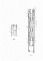
На Фиг. 1 показан привод погружной насосной установки с теплообменником расположенный в скважине.FIG. 1 shows the drive of a submersible pumping unit with a heat exchanger located in the well.
На Фиг. 2 показан теплообменник с установленным диафрагменным компенсатором.FIG. 2 shows a heat exchanger with a diaphragm expansion joint installed.
Осуществление полезной моделиImplementation of the utility model
Привод погружной насосной установки с теплообменником, содержит заполненный диэлектрической жидкостью электродвигатель 1 (протектор (не указан)) - размещается выше электродвигателя), присоединенный к нему снизу теплообменник 2 со встроенным компенсатором 12. Привод размещен в скважине (см. Фиг. 1) и окружен скважинной жидкостью в затрубном пространстве 36 (пространство преимущественно кольцевой формы между внешней поверхностью погружной части насосной установки и стенками скважины).The drive of a submersible pumping unit with a heat exchanger contains an
Двухконтурный теплообменник с компенсатором крепится к силовой части (электродвигательной секции) при помощи фланца крепления 3 к силовой части, шпилек 5, гаек 6. В нем располагаются масляные каналы 25, 26 разделенные втулкой 4. Двухконтурный теплообменник 2 с компенсатором содержит верхний 7 и нижний 16 фланцы, корпус 8, гильзу теплообменника 10. Гильза 10 может выполнена металлической с винтовой проволочной обмоткой ее внешней поверхности для интенсификации теплообменных процессов - в случае, если ее внешняя поверхность формирует часть поверхности канала для масла (с направлением потока 24).A double-circuit heat exchanger with a compensator is attached to the power section (electric motor section) by means of a flange 3 to the power section, studs 5, nuts 6. It contains oil channels 25, 26 separated by a bushing 4. A double-
Компенсатор с диафрагмой в виде мешка 12 крепится при помощи втулок 9, 14, 27 и гильз 11. Такая диафрагма компенсатора вытянута в вертикальном направлении и практически всегда выполняется из эластомерного материала.The compensator with a diaphragm in the form of a bag 12 is attached by means of bushings 9, 14, 27 and sleeves 11. Such a diaphragm of the compensator is extended in the vertical direction and is almost always made of an elastomeric material.
Наружная поверхность компенсатора ограничена жестким цилиндрическим кожухом 13 из теплопроводящего материала (обычно из металла), установленным на креплении 15. Во фланцах 7, 16 выполнены масляные входной и выходные участки (каналы) 19, 20 для циркуляционного канала для масла с потоком в направлении потока масла 24 (вниз) из электродвигателя для теплообмена между маслом и скважинной жидкостью, сформированного между внешней поверхностью гильзы 10 теплообменника и внутренней поверхностью корпуса теплообменника 8. Такой канал может иметь в поперечном сечении кольцевую форму.The outer surface of the compensator is limited by a rigid cylindrical casing 13 made of heat-conducting material (usually metal) mounted on the mount 15. In the flanges 7, 16 there are oil inlet and outlet sections (channels) 19, 20 for a circulation channel for oil with flow in the direction of oil flow 24 (downward) from an oil-well fluid heat exchange motor formed between the outer surface of the heat exchanger sleeve 10 and the inner surface of the heat exchanger body 8. Such a channel may have an annular cross-sectional shape.
Также во фланцах 7, 16 выполнены выход и вход (канальные отверстия для подвода вывода жидкости в сквозной канал для скважинной жидкости в теплообменнике) соответственно для протока скважинной жидкости 17, 18 (выхода и входа потока скважинной жидкости из затрубного пространства 36). Направление потоков скважинной жидкости указано стрелками 21, 22, направление потоков масла 23, 24. Для герметизации внутренней полости электродвигателя используются резиновые кольца 28, 29, 30, 31, 32, 33, а для разделения потоков масла кольца 35.Also in the flanges 7, 16 there is an outlet and an inlet (channel openings for supplying the liquid outlet to the through channel for the well fluid in the heat exchanger), respectively, for the well
Пример осуществления полезной моделиAn example of implementation of a utility model
Устройство работает следующим образом. Масло в электродвигателе поглощает тепло работающего электродвигателя и отводит его в скважинную жидкость. Потоки масла проходят через электродвигатель и теплообменник. А именно, масло (диэлектрическая охлаждающая жидкость) из электродвигателя двигателя циркулирует по каналам (маслопроводам), обеспечивающим циркуляцию масла в приводе для теплообмена между маслом и скважинной жидкостью (например, циркуляционным масляным насосом). Указанную циркуляцию масла обеспечивают в частности, входной канал 19, связанный с маслозаполненной полостью двигателя и обеспечивающий поступление масла в кольцевой канал для циркуляции масла в направлении 24 по теплообменнику. Канал с маслом 26 обеспечивает также работу компенсатора с диафрагмой, содержащей дополнительное диэлектрическое масло в своей внутренней полости для компенсации температурного расширения масла в полости электродвигателя (и восполнения неизбежных утечек масла из маслозаполненной зоны электродвигателя).The device works as follows. The oil in the electric motor absorbs heat from the running electric motor and dissipates it into the well fluid. The oil flows through the electric motor and heat exchanger. Namely, the oil (dielectric coolant) from the motor electric motor circulates through the channels (oil lines) circulating the oil in the actuator for heat exchange between the oil and the well fluid (for example, a circulating oil pump). Said oil circulation is provided, in particular, by an inlet channel 19 connected to the oil-filled cavity of the engine and allowing oil to flow into an annular channel for oil circulation in the direction 24 along the heat exchanger. The channel with oil 26 also ensures the operation of a compensator with a diaphragm containing additional dielectric oil in its internal cavity to compensate for the thermal expansion of the oil in the cavity of the electric motor (and to compensate for the inevitable oil leaks from the oil-filled zone of the electric motor).
В сквозной канал теплообменника (часть внутреннего контура теплообменника) для протока скважинной жидкости через входное отверстие 18 (канал во фланце) поступает скважинная жидкость из затрубного пространства со скважинной жидкостью 36. Далее поток скважинной жидкости в заданном направлении 22 движется по каналу кольцевого поперечного сечения с внутренней стенкой, сформированной внешней боковой поверхностью цилиндрического кожуха 13 и с внешней стенкой, сформированной внутренней поверхностью цилиндрической гильзы теплообменника 10. Этот поток обеспечивает одновременно:In the through channel of the heat exchanger (part of the internal circuit of the heat exchanger) for the flow of the well fluid through the inlet 18 (channel in the flange), the well fluid flows from the annular space with the
охлаждение компенсатора с диафрагмой 12 (через тонкостенный (например, толщиной менее 2 мм) цилиндрический стальной кожух 13) - такое охлаждение продлевает ресурс диафрагменного компенсатора, диафрагма которого выполнена из эластомерного материала (типа резина), создавая более благоприятный температурный режим для диафрагмы;cooling of the expansion joint with a diaphragm 12 (through a thin-walled (for example, less than 2 mm thick) cylindrical steel casing 13) - such cooling prolongs the life of the diaphragm expansion joint, the diaphragm of which is made of an elastomeric material (rubber type), creating a more favorable temperature regime for the diaphragm;
теплоизоляцию компенсатора от горячей зоны - циркуляционного канала для масла из электродвигателя для теплообмена между маслом и скважинной жидкостью, сформированного между внешней поверхностью гильзы теплообменника 10 и внутренней поверхностью корпуса теплообменника 8, что также создает более благоприятный температурный режим для диафрагмы -прежде всего для ее эластомерных элементов (мешка диафрагмы);thermal insulation of the compensator from the hot zone - the circulation channel for oil from the electric motor for heat exchange between oil and well fluid, formed between the outer surface of the heat exchanger sleeve 10 and the inner surface of the heat exchanger body 8, which also creates a more favorable temperature regime for the diaphragm, primarily for its elastomeric elements (diaphragm bag);
вносит вклад в охлаждение вышеуказанного циркуляционного канала для масла (с потоком 24) из электродвигателя для теплообмена между маслом и скважинной жидкостью.contributes to cooling the above oil circulation channel (flow 24) from the electric motor for heat exchange between oil and well fluid.
В целом создание такого второго (внутреннего) контура со сквозным каналом для протока скважинной жидкости в теплообменнике) может увеличивать поверхность теплообмена почти в 2 раза при сохранении длины теплообменника.In general, the creation of such a second (internal) loop with a through channel for the flow of the well fluid in the heat exchanger) can increase the heat exchange surface by almost 2 times while maintaining the length of the heat exchanger.
В первом контуре (внешнем) проходящий поток масла в направлении 24 в циркуляционном канале для масла из электродвигателя для теплообмена между маслом и скважинной жидкостью (сформированный между гильзой и корпусом теплообменника) охлаждается также потоком скважинной жидкости в затрубном пространстве в направлении 21 (т.е. в противоположном направлении потоку скважинной жидкости).In the first circuit (external), the flowing oil flow in direction 24 in the oil circulation channel from the electric motor for heat exchange between the oil and the well fluid (formed between the liner and the heat exchanger body) is also cooled by the well fluid flow in the annulus in direction 21 (i.e. in the opposite direction to the wellbore fluid flow).
Расположение теплообменника электродвигателя ниже двигателя может быть целесообразным, когда насосная установка размещена в стволе скважины выше зоны перфорационных отверстий (в обсадной трубе в требуемых местоположениях могут выполнены «перфорационные отверстия», обеспечивающие возможность проникновения текучих сред из продуктивной формации в обсадную трубу). При такой компоновке текучая среда, втягиваемая в ствол скважины проходит, в частности, по наружной части теплообменника, прежде чем она будет нагрета двигателем. Это способствует более эффективной работе теплообменника.Positioning the motor heat exchanger below the motor may be beneficial when the pumping unit is located in the wellbore above the perforation zone (perforations can be made in the casing at desired locations to allow fluids from the formation to enter the casing). With this arrangement, the fluid drawn into the wellbore passes, in particular, along the outside of the heat exchanger before it is heated by the engine. This contributes to more efficient operation of the heat exchanger.
Рассмотренная система принудительного охлаждения относится к двухконтурным теплобменникам и необходима из-за малого габарита силовой части и интенсивного тепловыделения в ней. В такой системе всегда необходим эффективный теплообменник и создание интенсивной циркуляции потоков (масла и скважинной жидкости) через него. Поскольку это конструктивное решение уменьшает объем масла (при использовании одномешкового компенсатора), которое нагревается и расширяется при работе электродвигателя, то крайне желательно использования увеличенного компенсатора изменений объема масла (двухмешкового компенсатора). Поэтому компенсатор крайне желательно выполнять двухмешковым, при котором конструкция соединения мешков предусматривает минимальный габарит изделия. Конструктивно предлагаемое техническое решение - двухконтурный теплообменник с компенсатором выполняется из труб расчетной длины, соответствующей необходимому охлаждению силовой части при работе в номинальном режиме. Все основные конструктивные элементы теплообменника кроме диафрагмы компенсатора, в частности, нижний 16 и верхний фланцы 7, цилиндрический кожух 13, цилиндрическая гильза теплообменника 10, корпус 8 могут быть изготовлены из стали - в частности углеродистой стали или (для коррозионностойкого исполнения) нержавеющая стали. Типичная толщина цилиндрической гильзы 10 от 2 мм до 6,5 мм. Кожуха 13 от - 0,5 до 2 мм, корпуса 8 - от 4 до 7 мм. Диапазон внешних диаметров корпуса 8 например, от 103 мм до 185 мм.The considered forced cooling system refers to double-circuit heat exchangers and is necessary due to the small size of the power section and the intense heat release in it. Such a system always requires an efficient heat exchanger and the creation of intensive circulation of flows (oil and well fluid) through it. Since this design solution reduces the volume of oil (when using a one-bag expansion joint) that heats up and expands during operation of the electric motor, it is highly desirable to use an enlarged compensator for changes in oil volume (two-bag expansion joint). Therefore, it is highly desirable to make a double-bag compensator, in which the design of the connection of the bags provides for the minimum size of the product. Structurally, the proposed technical solution - a double-circuit heat exchanger with a compensator is made of pipes of the calculated length corresponding to the required cooling of the power unit when operating in the nominal mode. All the main structural elements of the heat exchanger except the compensator diaphragm, in particular the lower 16 and upper flanges 7, the cylindrical casing 13, the cylindrical heat exchanger sleeve 10, the housing 8 can be made of steel - in particular carbon steel or (for corrosion-resistant performance) stainless steel. Typical thickness for cylindrical sleeve 10 is 2 mm to 6.5 mm. Casing 13 from - 0.5 to 2 mm, cases 8 - from 4 to 7 mm. The range of outside diameters of the body 8 is for example from 103 mm to 185 mm.
Диаметры входных и выходного каналов 7,18 - от 3 до 15 мм. Типичный диапазон толщины проточного канала маслопровода - от 1,5 до 3 мм.The diameters of the inlet and outlet channels are 7.18 - from 3 to 15 mm. Typical oil line flow channel thicknesses range from 1.5 to 3 mm.
Расположение теплообменника электродвигателя ниже двигателя может быть целесообразным в применениях, в которых насосная установка размещена в стволе скважины выше зоны перфорационных отверстий (в обсадной трубе в требуемых местоположениях могут выполнены «перфорационные отверстия», обеспечивающие возможность проникновения текучих сред из продуктивной формации в обсадную трубу). При такой компоновке текучая среда, втягиваемая в ствол скважины проходить в частности по наружной части теплообменника, прежде чем она будет нагрета электродвигателем двигателем (протектор гидрозащиты может быть размещен выше электродвигателя). В иных случаях допускается применение кожуха принудительного обтекания.Positioning the motor heat exchanger below the engine may be beneficial in applications where the pumping unit is located in the wellbore above the perforation zone (perforations may be made in the casing at desired locations to allow fluids from the formation to enter the casing). With this arrangement, the fluid drawn into the wellbore passes in particular along the outer part of the heat exchanger before it is heated by the electric motor (the hydraulic protector can be placed above the electric motor). In other cases, the use of a forced flow casing is allowed.
Разработанный привод с указанным теплообменником обеспечивает повышение теплоотдачи. В нем обеспечена увеличенная скорость теплоотдачи по внутреннему контуру. Использование электрического привода погружного насоса с таким теплообменником обеспечивает повышение компактности теплообменника для погружного маслозаполненного электродвигателя и эффективное поддержание заданного рабочего интервала температур маслозаполненного электродвигателя что, в конечном счете, продлевает ресурс насосной установки.The developed drive with the specified heat exchanger provides increased heat transfer. It provides an increased rate of heat transfer along the inner contour. The use of an electric drive of a submersible pump with such a heat exchanger provides an increase in the compactness of the heat exchanger for a submersible oil-filled electric motor and effective maintenance of the specified operating temperature range of the oil-filled electric motor, which ultimately prolongs the life of the pumping unit.
Claims (2)
Priority Applications (1)
| Application Number | Priority Date | Filing Date | Title |
|---|---|---|---|
| RU2020132704U RU201788U1 (en) | 2020-10-05 | 2020-10-05 | SUBMERSIBLE PUMP UNIT DRIVE WITH A HEAT EXCHANGER |
Applications Claiming Priority (1)
| Application Number | Priority Date | Filing Date | Title |
|---|---|---|---|
| RU2020132704U RU201788U1 (en) | 2020-10-05 | 2020-10-05 | SUBMERSIBLE PUMP UNIT DRIVE WITH A HEAT EXCHANGER |
Publications (1)
| Publication Number | Publication Date |
|---|---|
| RU201788U1 true RU201788U1 (en) | 2021-01-13 |
Family
ID=74183603
Family Applications (1)
| Application Number | Title | Priority Date | Filing Date |
|---|---|---|---|
| RU2020132704U RU201788U1 (en) | 2020-10-05 | 2020-10-05 | SUBMERSIBLE PUMP UNIT DRIVE WITH A HEAT EXCHANGER |
Country Status (1)
| Country | Link |
|---|---|
| RU (1) | RU201788U1 (en) |
Citations (7)
| Publication number | Priority date | Publication date | Assignee | Title |
|---|---|---|---|---|
| US5028218A (en) * | 1988-06-11 | 1991-07-02 | Grundfos International A/S | Immersion pump assembly |
| RU2293217C1 (en) * | 2005-09-15 | 2007-02-10 | Общество с ограниченной ответственностью "Научно-Производственный Комплекс "Нефтемаш" | Submersible pumping set with forced cooling system of drive electric motor |
| RU2301912C1 (en) * | 2005-10-27 | 2007-06-27 | Закрытое Акционерное Общество "Новомет-Пермь" | Heat exchanger for submersible oil-filled electric motor |
| RU2464691C1 (en) * | 2011-04-08 | 2012-10-20 | Закрытое акционерное общество "Новые технологии по повышению нефтеотдачи" | Pump plant drive |
| EP2539994B1 (en) * | 2010-02-26 | 2013-12-18 | Flowserve Management Company | Cooling system for a multistage electric motor |
| US20190032459A1 (en) * | 2016-03-12 | 2019-01-31 | Baker Hughes, A Ge Company, Llc | Active and Passive Refrigeration Systems for Downhole Motors |
| RU2686971C2 (en) * | 2014-05-19 | 2019-05-06 | ДжиИ ОЙЛ ЭНД ГЭС ЭСП, ИНК. | Optimised cooling of electric motor in pump compressor formation |
-
2020
- 2020-10-05 RU RU2020132704U patent/RU201788U1/en active
Patent Citations (7)
| Publication number | Priority date | Publication date | Assignee | Title |
|---|---|---|---|---|
| US5028218A (en) * | 1988-06-11 | 1991-07-02 | Grundfos International A/S | Immersion pump assembly |
| RU2293217C1 (en) * | 2005-09-15 | 2007-02-10 | Общество с ограниченной ответственностью "Научно-Производственный Комплекс "Нефтемаш" | Submersible pumping set with forced cooling system of drive electric motor |
| RU2301912C1 (en) * | 2005-10-27 | 2007-06-27 | Закрытое Акционерное Общество "Новомет-Пермь" | Heat exchanger for submersible oil-filled electric motor |
| EP2539994B1 (en) * | 2010-02-26 | 2013-12-18 | Flowserve Management Company | Cooling system for a multistage electric motor |
| RU2464691C1 (en) * | 2011-04-08 | 2012-10-20 | Закрытое акционерное общество "Новые технологии по повышению нефтеотдачи" | Pump plant drive |
| RU2686971C2 (en) * | 2014-05-19 | 2019-05-06 | ДжиИ ОЙЛ ЭНД ГЭС ЭСП, ИНК. | Optimised cooling of electric motor in pump compressor formation |
| US20190032459A1 (en) * | 2016-03-12 | 2019-01-31 | Baker Hughes, A Ge Company, Llc | Active and Passive Refrigeration Systems for Downhole Motors |
Similar Documents
| Publication | Publication Date | Title |
|---|---|---|
| CN101675249B (en) | Compressor system for underwater use in the offshore area | |
| RU2686971C2 (en) | Optimised cooling of electric motor in pump compressor formation | |
| US8696327B2 (en) | Submersible pump motor cooling through external oil circulation | |
| CN102823117B (en) | Cooling system for multistage electric motor | |
| US20100329908A1 (en) | Heat exchanger for esp motor | |
| GB2288694A (en) | Downhole motor cooling and protection system | |
| BR112021006082A2 (en) | active and passive cooling systems for downhole engines | |
| CN102624121A (en) | Cooling structure for motor winding end part | |
| CN103629118A (en) | Vertical pipeline permanent magnet canned motor pump | |
| TW201725835A (en) | Compact hydrostatic assembly with cooling | |
| RU201788U1 (en) | SUBMERSIBLE PUMP UNIT DRIVE WITH A HEAT EXCHANGER | |
| US20230184070A1 (en) | Submersible pump unit drive heat exchanger having a diaphragm compensator | |
| CN104131982B (en) | Special rectifying device oil pump is planted in special transformer and integration | |
| US10125585B2 (en) | Refrigeration system with internal oil circulation | |
| RU2301912C1 (en) | Heat exchanger for submersible oil-filled electric motor | |
| JPS61118595A (en) | Cooling device for submersible pump | |
| WO2012173985A2 (en) | Systems and methods of using subsea frames as a heat exchanger in subsea boosting systems | |
| RU2294457C1 (en) | Oil-well electric pumping unit | |
| CN114278554A (en) | Integrated device of plunger pump | |
| RU2756625C2 (en) | Submersible striction pumping plant | |
| RU2136970C1 (en) | Electromersible pump | |
| RU44766U1 (en) | UETS SUBMERSIBLE INSTALLATION WITH ADDITIONAL SUBMERSIBLE ELECTRIC MOTOR HOUSING, PROVIDING FORCED FORMATION OF PLASTIC LIQUID FOR COOLING SUBMERSIBLE ELECTRIC MOTOR | |
| US20150114722A1 (en) | Downhole screw motor | |
| RU2754103C1 (en) | High temperature pump | |
| SU1042139A1 (en) | Submersible liquid-packed electric motor |