RU2017449C1 - Apparatus for foodstuff mixing - Google Patents
Apparatus for foodstuff mixing Download PDFInfo
- Publication number
- RU2017449C1 RU2017449C1 SU4952064A RU2017449C1 RU 2017449 C1 RU2017449 C1 RU 2017449C1 SU 4952064 A SU4952064 A SU 4952064A RU 2017449 C1 RU2017449 C1 RU 2017449C1
- Authority
- RU
- Russia
- Prior art keywords
- shaft
- frame
- gear
- symmetry
- blades
- Prior art date
Links
Images
Abstract
Description
Изобретение относится к оборудованию предприятий общественного питания и может быть использовано для измельчения, перемешивания и взбивания пищевых продуктов при производстве теста, кондитерских кремов и других вязких пищевых продуктов или полуфабрикатов. The invention relates to the equipment of public catering enterprises and can be used for grinding, mixing and whipping food products in the production of dough, confectionery creams and other viscous food products or semi-finished products.
Известно устройство для взбивания и перемешивания пищевых продуктов, выполненное в виде плоскорешетчатой лопасти, снабженной хвостовиком для закрепления в шпинделе взбивальной машины. A device for whipping and mixing food products, made in the form of a flat-mesh blade, equipped with a shank for fixing in the spindle of a whipping machine.
Недостатком этого устройства является невозможность измельчения охлажденных жиров и сухих продуктов, низкая надежность и производительность из-за отсутствия боковых режущих кромок и отсутствия поворотных лопастей. The disadvantage of this device is the inability to grind chilled fats and dry foods, low reliability and performance due to the lack of side cutting edges and the absence of rotary blades.
Известно устройство для перемешивания пищевых продуктов, содержащее установленную на вертикальном валу плоскую рамку, внутри которой по обе стороны оси симметрии смонтированы лопатки, снабженные приводом их поворота, включающим коромысла, шайбу и шатуны, каждый из которых имеет тягу и штифт, шарнирно связанный с тягой. Штифт радиально смонтирован на шайбе, выполненной с возможностью фиксированного поворота в горизонтальной плоскости относительно вала. Каждая лопатка шарнирно связана с рамкой посредством осей, верхние оси порознь связаны с одними концами коромысел, а их другие концы с каждой стороны оси симметрии рамки шарнирно связаны шатунами. При этом лопатки выполнены вогнуто-выпуклой формы в поперечном сечении. A device for mixing food products is known, comprising a flat frame mounted on a vertical shaft, inside of which blades are mounted on both sides of the axis of symmetry, equipped with a drive for turning them, including rocker arms, washer and connecting rods, each of which has a rod and a pin pivotally connected to the rod. The pin is radially mounted on a washer, made with the possibility of a fixed rotation in a horizontal plane relative to the shaft. Each blade is pivotally connected to the frame by means of axes, the upper axes are separately connected with one ends of the rocker arm, and their other ends on each side of the axis of symmetry of the frame are pivotally connected by rods. The blades are concave-convex in cross section.
Недостатком этого устройства является сложность конструкции, низкая надежность и узкий диапазон использования из-за наличия большого количества звеньев и кинематических пар, а также отсутствия устройства для автоматического поворота лопастей при изменении вязкости перемешиваемой среды. The disadvantage of this device is the design complexity, low reliability and a narrow range of use due to the presence of a large number of links and kinematic pairs, as well as the lack of a device for automatically turning the blades when the viscosity of the mixed medium changes.
Цель изобретения - упрощение конструкции, расширение функциональных возможностей и повышение надежности в работе. The purpose of the invention is to simplify the design, expand functionality and increase reliability in operation.
Цель достигается тем, что в верхней части вала под хвостовиком установлена зубчатая шестерня, а на верхних полуосях - зубчатые колеса, смонтированные с возможностью взаимодействия с упомянутой шестерней. Вал выполнен в виде упругого элемента кручения. Нижний конец вала зафиксирован в нижней полке рамки, а верхний конец шарнирно связан с ее верхней полкой с возможностью относительного поворота в горизонтальной плоскости. При этом в верхней части вала и в зубчатой шестерне выполнены радиальные каналы, расположенные в одной горизонтальной плоскости, а в последних размещен штифт для предотвращения их относительного поворота. The goal is achieved by the fact that in the upper part of the shaft a gear is installed under the shank, and on the upper half shafts - gears mounted with the possibility of interaction with the said gear. The shaft is made in the form of an elastic torsion element. The lower end of the shaft is fixed in the lower shelf of the frame, and the upper end is pivotally connected to its upper shelf with the possibility of relative rotation in the horizontal plane. At the same time, radial channels located in the same horizontal plane are made in the upper part of the shaft and in the gear gear, and a pin is placed in the latter to prevent their relative rotation.
Кроме того, вал выполнен съемным, а каждая лопасть представляет собой плоскую пластину с режущими кромками, вертикальная ось вращения которой совмещена с продольной осью ее симметрии. In addition, the shaft is removable, and each blade is a flat plate with cutting edges, the vertical axis of rotation of which is combined with the longitudinal axis of its symmetry.
Кроме того, устройство снабжено комплектом сменных валов, имеющих различные упругие характеристики для поочередной установки в рамку при значительном изменении силового или скоростного режима работы устройства. In addition, the device is equipped with a set of interchangeable shafts having different elastic characteristics for alternate installation in the frame with a significant change in the power or speed mode of operation of the device.
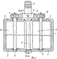
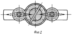
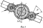
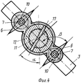
На фиг. 1 показан общий вид перемешивающего устройства, вид сбоку; на фиг. 2 - положение лопастей относительно рамки при выключении привода машины, вид сверху; на фиг. 3 - положение лопастей при включенном приводе машины в одном из текущих значений вязкости перемешиваемого продукта, вид сверху; на фиг. 4 - положение лопастей, соответствующее максимально допустимой вязкости продукта и включенном приводе машины, вид сверху. In FIG. 1 shows a general view of a mixing device, side view; in FIG. 2 - the position of the blades relative to the frame when turning off the drive of the machine, top view; in FIG. 3 - the position of the blades when the drive of the machine in one of the current values of the viscosity of the mixed product, top view; in FIG. 4 - the position of the blades corresponding to the maximum allowable viscosity of the product and the included drive of the machine, top view.
Устройство для перемешивания пищевых продуктов содержит замкнутую плоскую рамку 1 с нижней 2 и верхней 3 горизонтальными полками. Внутри рамки 1, вдоль ее оси симметрии на указанных полках закреплен вертикальный вал 4 с хвостовиком 5, смонтированным на верхнем конце вала. Вал 4 выполнен в виде упругого элемента кручения /торсиона/. Хвостовик 5 предназначен для установки и закрепления в шпинделе перемешивающей машины. Нижний конец вала 4 закреплен в нижней полке 2 рамки 1, а верхняя часть вала 4 связана с верхней полкой 3 с возможностью относительного поворота в горизонтальной плоскости. По обе стороны вала 4 внутри рамки 1 симметрично и вертикально установлены лопасти 6, шарнирно связанные с рамкой 1 верхней 7 и нижней 8 полуосями с возможностью поворота в горизонтальной плоскости относительно оси 9 лопасти 6. В верхней части вала 4, на верхней полуоси 7 каждой лопасти 6 соосно закреплено зубчатое колесо 10, зацепленное с установленной на ступице 11 в верхней части вала 4 шестерней 12. Нижний конец 13 вала 4 выполнен квадратного сечения и вставлен в квадратное окно 14 нижней полки 2 с целью взаимной фиксации. В ступице 11 и шестерне 12 выполнены в единой горизонтальной плоскости сквозные радиальные каналы 15 и 16, в которых размещен штифт 17, предотвращающий взаимное проворачивание шестерни 12 относительно вала 4. A device for mixing food products contains a closed
Устройство работает следующим образом. Рамку 1 с лопастями 6 опускают в емкость, заполненную пищевыми продуктами, а хвостовик 5 закрепляют в шпинделе перемешивающей машины, расположенном над указанной емкостью. При выключенном приводе машины, когда отсутствует давление вязкого продукта на лопасти 6, последние расположены в плоскости рамки 1, а вал 4 разгружен от воздействия момента кручения. The device operates as follows.
При включении привода перемешивающей машины вал 4 начинает вращаться. При этом на лопасти 6 будут действовать силы давления со стороны перемешиваемого продукта, величина которых будет тем больше, чем больше вязкость продукта и чем выше угловая скорость вращения шпинделя. Под воздействием этих сил лопасти 6 вместе с рамкой 1 и нижним концом 13 вала 4 будут поворачиваться относительно хвостовика 5, закручивая вал 4. При этом зубчатые колеса 10, зацепленные с неподвижной относительно хвостовика 5 шестерней 12, будут обкатываться вокруг нее, совершая планетарное движение, а полуоси 7 лопастей 6, жестко связанные с зубчатым колесом 10, будут изменять угол поворота самих лопастей 6 относительно рамки 1. Причем этот угол будет тем больше, чем больше сумма площадей пластин, расположенных с противоположных сторон осей вращения 9, чем больше расстояние от оси вращения лопасти 6 до оси вала 4, чем выше скорость вращения вала 4 и выше вязкость перемешиваемого продукта. На угол закручивания лопастей 6 влияют также упругие свойства самого вала 4. When you turn on the drive of the mixing machine, the shaft 4 begins to rotate. In this case, pressure forces from the side of the mixed product will act on the
В начальный период процесса перемешивания, когда сопротивление набегающего на лопасть продукта велико, лопасти 6, поворачиваясь относительно рамки 1, будут уменьшать площадь лобового сопротивления, а режущие кромки могут измельчать продукт без значительных затрат энергии. При снижении вязкости продукта в процессе его обработки /в результате таяния охлажденных жиров, добавки жидких маловязких компонентов/, лопасти 6 будут возвращаться в исходное положение под действием потенциальной энергии, накопленной валом 4 в результате его закручивания. При этом лобовое сопротивление лопастей 6 будет увеличиваться, а интенсивность процесса перемешивания продукта - возрастать, что приводит в конечном итоге к повышению производительности технологического процесса. In the initial period of the mixing process, when the resistance of the product incident on the blade is large, the
Таким образом, заявленное устройство позволяет поддерживать в автоматическом режиме оптимальные затраты энергии на выполнение процесса перемешивания при изменении вязкости продукта или изменении скорости вращения шпинделя машины. Thus, the claimed device allows you to automatically maintain optimal energy costs for the mixing process when changing the viscosity of the product or changing the speed of rotation of the spindle of the machine.
Так как на угол поворота лопастей 6 относительно рамки 1 влияет сумма площадей их, а не разность /как это имеет место у прототипа/, то форма лопасти может быть выполнена конструктивно проще, т.е. может быть плоской, а не выпукло-вогнутой, и ось вращения лопасти 6 можно совмещать с осью ее симметрии. Это позволяет упростить не только конструкцию заявленного устройства, но и улучшить технологичность его изготовления. Since the angle of rotation of the
Угол поворота лопастей, а следовательно и угол закручивания нижнего конца вала 4 относительно хвостовика 5, можно изменять путем установки различного передаточного отношения между зубчатым колесом и шестерней, а также путем поочередной установки в рамку 1 сменных валов 4 с различными их упругими характеристиками. Это дает возможность расширить область применения заявленного устройства для перемешивания продуктов, изменяющих по времени свою вязкость в широких пределах, а также применять в машинах, имеющих большой диапазон изменения скоростного режима шпинделя. The angle of rotation of the blades, and therefore the angle of twisting of the lower end of the shaft 4 relative to the
Так как боковые кромки лопастей выполнены режущими, то заявленное устройство может быть использовано для измельчения охлажденных жиров, или измельчения и перемешивания овощей при производстве салатов. Since the lateral edges of the blades are made cutting, the claimed device can be used to grind chilled fats, or chop and mix vegetables in the production of salads.
Claims (3)
Priority Applications (1)
| Application Number | Priority Date | Filing Date | Title |
|---|---|---|---|
| SU4952064 RU2017449C1 (en) | 1991-06-28 | 1991-06-28 | Apparatus for foodstuff mixing |
Applications Claiming Priority (1)
| Application Number | Priority Date | Filing Date | Title |
|---|---|---|---|
| SU4952064 RU2017449C1 (en) | 1991-06-28 | 1991-06-28 | Apparatus for foodstuff mixing |
Publications (1)
| Publication Number | Publication Date |
|---|---|
| RU2017449C1 true RU2017449C1 (en) | 1994-08-15 |
Family
ID=21582758
Family Applications (1)
| Application Number | Title | Priority Date | Filing Date |
|---|---|---|---|
| SU4952064 RU2017449C1 (en) | 1991-06-28 | 1991-06-28 | Apparatus for foodstuff mixing |
Country Status (1)
| Country | Link |
|---|---|
| RU (1) | RU2017449C1 (en) |
Cited By (1)
| Publication number | Priority date | Publication date | Assignee | Title |
|---|---|---|---|---|
| RU2570492C2 (en) * | 2012-02-21 | 2015-12-10 | Борис Лаврович Макеев | Device for preparing first courses for distribution in public catering canteens |
-
1991
- 1991-06-28 RU SU4952064 patent/RU2017449C1/en active
Non-Patent Citations (2)
| Title |
|---|
| Авторское свидетельство СССР N 1597169, кл. A 47J 43/04, 1990. * |
| Патент Франции N 2493692, кл. A 47J 43/04, 1982. * |
Cited By (1)
| Publication number | Priority date | Publication date | Assignee | Title |
|---|---|---|---|---|
| RU2570492C2 (en) * | 2012-02-21 | 2015-12-10 | Борис Лаврович Макеев | Device for preparing first courses for distribution in public catering canteens |
Similar Documents
| Publication | Publication Date | Title |
|---|---|---|
| US3752057A (en) | Portable scraper-type mixer | |
| US20020172091A1 (en) | Apparatus for processing the ingredients of foods/beverages | |
| US4998464A (en) | Heat exchange device for food | |
| EP2740368A1 (en) | Chocolate tempering apparatus with planetary mixers | |
| RU2017449C1 (en) | Apparatus for foodstuff mixing | |
| US1823314A (en) | Kitchen appliance machine | |
| US4763570A (en) | Pasta preparation apparatus | |
| KR100452091B1 (en) | Mixing machine for seasoning fried stuff | |
| DK2740367T3 (en) | Chocolate tempering apparatus with planetary mixers | |
| KR101022154B1 (en) | Mixer device | |
| US4671172A (en) | Apparatus for mixing food ingredients | |
| FI81489C (en) | Apparatus for whipping and mixing liquids and butter | |
| CN208435223U (en) | Artificial stir-frying emulation cooking robot | |
| CN115400671B (en) | Stirring and mixing device for biological composite seasoning | |
| CN209810648U (en) | Novel preserved fruit screening device | |
| CN207385360U (en) | A kind of high-viscosity stirring sandwich pot with agitating device | |
| US4656934A (en) | Pasta preparation apparatus | |
| US2324179A (en) | Mixing machine | |
| US1015337A (en) | Culinary separating-machine. | |
| CN212521564U (en) | Small-size salad mixer for kitchen use | |
| EP3488743B1 (en) | Mixer with dual drive function on a shaft | |
| CN207619402U (en) | A kind of use for laboratory tissue mashing refiner | |
| RU1792636C (en) | Beating machine | |
| CN217989506U (en) | Crushing apparatus is used in meal replacement powder production | |
| CN216062758U (en) | Food essence production is with mixing emulsion machine |