RU2015114C1 - Compact unit for sewage purification - Google Patents
Compact unit for sewage purification Download PDFInfo
- Publication number
- RU2015114C1 RU2015114C1 SU915016946A SU5016946A RU2015114C1 RU 2015114 C1 RU2015114 C1 RU 2015114C1 SU 915016946 A SU915016946 A SU 915016946A SU 5016946 A SU5016946 A SU 5016946A RU 2015114 C1 RU2015114 C1 RU 2015114C1
- Authority
- RU
- Russia
- Prior art keywords
- sludge
- reaeration
- jet
- aeration
- aerators
- Prior art date
Links
- 239000010865 sewage Substances 0.000 title claims abstract description 8
- 238000000746 purification Methods 0.000 title abstract description 4
- 239000010802 sludge Substances 0.000 claims abstract description 50
- 238000005273 aeration Methods 0.000 claims abstract description 30
- 238000005276 aerator Methods 0.000 claims abstract description 24
- 239000000203 mixture Substances 0.000 claims abstract description 19
- XLYOFNOQVPJJNP-UHFFFAOYSA-N water Substances O XLYOFNOQVPJJNP-UHFFFAOYSA-N 0.000 claims description 14
- 238000007599 discharging Methods 0.000 claims description 3
- 230000008929 regeneration Effects 0.000 abstract description 5
- 238000011069 regeneration method Methods 0.000 abstract description 5
- 238000005188 flotation Methods 0.000 abstract description 3
- 239000007921 spray Substances 0.000 abstract 1
- 239000000126 substance Substances 0.000 abstract 1
- 238000004065 wastewater treatment Methods 0.000 description 8
- 238000009434 installation Methods 0.000 description 7
- QVGXLLKOCUKJST-UHFFFAOYSA-N atomic oxygen Chemical compound [O] QVGXLLKOCUKJST-UHFFFAOYSA-N 0.000 description 4
- 229910052760 oxygen Inorganic materials 0.000 description 4
- 239000001301 oxygen Substances 0.000 description 4
- 239000002351 wastewater Substances 0.000 description 4
- 239000012530 fluid Substances 0.000 description 3
- 239000008213 purified water Substances 0.000 description 3
- 238000005192 partition Methods 0.000 description 2
- 238000004064 recycling Methods 0.000 description 2
- 229920006395 saturated elastomer Polymers 0.000 description 2
- 239000007787 solid Substances 0.000 description 2
- 238000004140 cleaning Methods 0.000 description 1
- 239000000356 contaminant Substances 0.000 description 1
- 238000000034 method Methods 0.000 description 1
- 244000005700 microbiome Species 0.000 description 1
- 239000002245 particle Substances 0.000 description 1
- 238000004062 sedimentation Methods 0.000 description 1
- 238000000926 separation method Methods 0.000 description 1
Images
Classifications
-
- Y—GENERAL TAGGING OF NEW TECHNOLOGICAL DEVELOPMENTS; GENERAL TAGGING OF CROSS-SECTIONAL TECHNOLOGIES SPANNING OVER SEVERAL SECTIONS OF THE IPC; TECHNICAL SUBJECTS COVERED BY FORMER USPC CROSS-REFERENCE ART COLLECTIONS [XRACs] AND DIGESTS
- Y02—TECHNOLOGIES OR APPLICATIONS FOR MITIGATION OR ADAPTATION AGAINST CLIMATE CHANGE
- Y02W—CLIMATE CHANGE MITIGATION TECHNOLOGIES RELATED TO WASTEWATER TREATMENT OR WASTE MANAGEMENT
- Y02W10/00—Technologies for wastewater treatment
- Y02W10/10—Biological treatment of water, waste water, or sewage
Landscapes
- Aeration Devices For Treatment Of Activated Polluted Sludge (AREA)
Abstract
Description
Изобретение относится к области биологической очистки сточных вод и может быть использовано в виде компактного сооружения для высокоэффективной обработки сточных вод малых населенных объектов. The invention relates to the field of biological wastewater treatment and can be used in the form of a compact structure for highly efficient wastewater treatment of small settlements.
Известна установка для очистки сточных вод - аэротенк-отстойник, содержащий центральную флотационную камеру с аэрационным устройством, камеры аэрации и реаэрации, вторичный отстойник с тонкослойным модулем, дегазатор, трубопроводы подвода исходных сточных вод, отвода очищенных вод и перепуска иловой смеси. A known installation for wastewater treatment - aeration tank-sump containing a central flotation chamber with an aeration device, aeration and reaeration chambers, a secondary sump with a thin-layer module, a degasser, pipelines for supplying raw wastewater, discharging treated water and passing the sludge mixture.
Однако известное устройство не обеспечивает высокой степени очистки сточных вод от органических загрязнений и взвешенных веществ из-за недостаточной циркуляции иловой смеси и регенерации активного ила, что снижает в целом производительность его. However, the known device does not provide a high degree of wastewater treatment from organic contaminants and suspended solids due to insufficient circulation of the sludge mixture and regeneration of activated sludge, which reduces its overall performance.
Цель изобретения - повышение степени очистки сточных вод и производительности установки путем обеспечения устойчивой рециркуляции и регенерации активного ила. The purpose of the invention is to increase the degree of wastewater treatment and plant productivity by ensuring sustainable recycling and regeneration of activated sludge.
Указанная цель достигается тем, что в установке, содержащей резервуар с центрально расположенным илоотделителем, сообщенные между собой камеры аэрации и реаэрации, аэраторы, вторичный отстойник с тонкослойным модулем, дегазатор, трубопроводы подвода исходных сточных вод, отвода очищенных вод и перепуска иловой смеси, аэраторы выполнены струйными с центральной воздушной трубой и нижним сжатым выпуском и установлены в верхней части илоотделителя, камер аэрации и реаэрации, трубопровод подвода исходных сточных вод выполнен напорным и присоединен к струйному аэратору илоотделителя, который снабжен вертикальной опускной трубой с реактивным распределителем на его нижнем конце, струйные аэраторы камеры аэрации снабжены присоединенными к нижним сжатым выпускам вертикальными опускными трубами с отводами на нижних их концах в виде колен, направленных в противоположные стороны для закручивания иловой смеси, а также илопроводами с насосами, сообщающими их с нижней частью вторичного отстойника, струйные аэраторы камеры аэрации снабжены илопроводами с насосами для циркуляции иловой смеси в камере. Предложенная система циркуляции и рециркуляции активного ила в установке обеспечивает высокоэффективный процесс очистки вследствие активной жизнедеятельности микроорганизмов, оптимального воздухообмена при сохранении индивидуального биоценоза в каждой камере сооружения. This goal is achieved by the fact that in an installation containing a tank with a centrally located sludge separator, aeration and reaeration chambers interconnected, aerators, a secondary settling tank with a thin-layer module, a degasser, pipelines for supplying raw sewage, discharging treated water and bypassing the sludge mixture, aerators are made jet with a central air pipe and a lower compressed outlet and installed in the upper part of the sludge separator, aeration and reaeration chambers, the pipeline for supplying initial wastewater is made pressure and connected to the sludge separator jet aerator, which is equipped with a vertical lowering pipe with a jet distributor at its lower end, the aeration chamber jet aerators are equipped with vertical lowering pipes connected to the lower compressed outlets with bends at their lower ends in the form of elbows directed in opposite directions for twisting the sludge mixture as well as iloproducts with pumps communicating them with the lower part of the secondary sedimentation tank, jet aerators of the aeration chamber are equipped with iloprovodami with pumps for circulation the sludge mixture in the chamber. The proposed system of circulation and recycling of activated sludge in the installation provides a highly efficient cleaning process due to the active life of microorganisms, optimal air exchange while maintaining an individual biocenosis in each chamber of the structure.
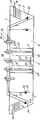
На чертеже изображена компактная установка для очистки сточных вод в продольном разрезе. The drawing shows a compact installation for wastewater treatment in longitudinal section.
Компактная установка для очистки сточных вод содержит резервуар 1, центрально расположенный илоотделитель 2, камеру 3 аэрации, камеру 4 реаэрации, вторичный отстойник 5 с тонкослойным модулем 6 и дегазатор 7 треугольной формы в продольном разрезе. Через продольную щель 8 дегазатор 7 сообщен с вторичным отстойником 5, а продольное отверстие 3 также в виде щели сообщает последний с камерой аэрации. Илоотделитель 2 выполнен в виде цилиндрического корпуса 10 на общем с резервуаром днище. В верхней части стенок цилиндрического корпуса 10 илоотделителя 2 выполнены щелевые перепускные окна 11, расположенные ниже горизонта воды. Сплошная перегородка 12 отделяет камеру 4 реаэрации от камеры 3 аэрации, но последняя сообщена с илоотделителем 2 перепусками 13. Установка имеет трубопровод 14 подвода исходных сточных вод, сборный лоток 15 очищенной воды и трубопровод 16 отвода очищенных вод. Аэрация обрабатываемой воды осуществляется струйными аэраторами 17, имеющими нижний сжатый выпуск 18 и центральную всасывающую воздушную трубу 19. Струйные аэраторы установлены в верхней части илоотделителя, камер аэрации и реаэрации. В илоотделителе и в камере реаэрации струйные аэраторы снабжены присоединенными к их сжатым выпускам вертикальными опускными трубами 20. В илоотделителе вертикальная труба снабжена присоединенным к его нижнему торцу реактивным распределителем 21, имеющим по разные стороны от трубы отверстия 22, направленные в противоположные стороны. Вертикальные трубы в камере реаэрации выполнены с отводами 23 в виде колен, направленных также в противоположные стороны для закручивания потоков водовоздушной смеси. Возврат ила из вторичного отстойника 5 в камеру 4 реаэрации осуществлен по напорному илопроводу 24, а циркуляция иловой смеси в камере 3 аэрации - при помощи напорного трубопровода 25 и насосов 26. Илопровод 24 соединен со струйным аэратором, установленным в камере 4 реаэрации, трубопровод 25 - cо cтруйным аэратором камеры аэрации. В перегородке, отделяющей камеру 3 аэрации от вторичного отстойника, выполнены регулируемые перепуски 27. A compact wastewater treatment plant comprises a tank 1, a centrally located
Компактная установка для очистки сточных вод работает следующим образом. A compact installation for wastewater treatment is as follows.
Исходная сточная вода, используемая также и в качестве рабочей жидкости, под напором поступает в струйный аэратор 17 илоотделителя 2, где насыщается кислородом воздуха и по опускной вертикальной трубе 20 поступает в нижнюю часть илоотделителя через отверстия 22 реактивного распределителя 21 закрученным потоком. Иловые частицы с пузырьками воздуха всплывают, образуя иловую смесь с повышенным содержанием ила, которая перетекает в камеру реаэрации через верхнюю кромку цилиндрического корпуса 10 илоотделителя 2, превышающую по высотным отметкам горизонт воды в камере 4 реаэрации и сборном лотке 15 вторичного отстойника 5. Иловая смесь с пониженной концентрацией активного ила по перепуску 13 поступает из илоотделителя в камеру 3 аэрации. The source wastewater, also used as a working fluid, flows under pressure into the
В камере аэрации осуществлена активная циркуляция иловой смеси путем забора ее через напорный трубопровод 25 при помощи насоса 26. Одновременно эта циркулирующая иловая смесь является рабочей жидкостью для струйных аэраторов, установленных над этой камерой. Из аэратора 17 водовоздушная смесь, обогащенная кислородом воздуха, возвращается в камеру аэрации - аэротенк. Через регулируемые перепуски 27 иловая смесь из камеры аэрации поступает во вторичный отстойник 5, где происходит гравитационное разделение воды от ила. Осветленная и очищенная вода, пройдя тонкослойный модуль 6, собирается в сборном лотке 15 и удаляется из установки по трубопроводу 16 отвода очищенной воды. Активный ил осаждается и через продольное отверстие - щель 9 возвращается в камеру аэрации. Возвратный ил из вторичного отстойника через напорный илопровод 24 поступает в струйный аэратор 17 камеры реаэрации. Возвратный ил в струйном аэраторе насыщается кислородом воздуха и одновременно благодаря напору является рабочей жидкостью для его работы. Водовоздушная смесь опускается по вертикальной трубе в нижнюю часть камеры 4 реаэрации и через отводы 23, установленные в противоположных направлениях, поступает в камеру в закрученном потоке. Из камеры 4 реаэрации регенерированный ил через перепускные окна 11 поступает в илоотделитель 2, часть его смешивается с поступающей на обработку водой, при этом обедненная по концентрации кислорода иловая смесь по перепуску 13 поступает в камеру аэрации, а иловая смесь с более высокой концентрацией возвращается в камеру 4 реаэрации, обеспечивая этим значительную разницу концентраций активного ила при регенерации и аэрации сточных вод. The sludge mixture was actively circulated in the aeration chamber by taking it through the
Компактная установка по изобретению обеспечивает высокую степень очистки и высокую производительность вследствие устойчивой рециркуляции и регенерации активного ила. The compact plant according to the invention provides a high degree of purification and high productivity due to the stable recirculation and regeneration of activated sludge.
Claims (1)
Priority Applications (1)
| Application Number | Priority Date | Filing Date | Title |
|---|---|---|---|
| SU915016946A RU2015114C1 (en) | 1991-12-17 | 1991-12-17 | Compact unit for sewage purification |
Applications Claiming Priority (1)
| Application Number | Priority Date | Filing Date | Title |
|---|---|---|---|
| SU915016946A RU2015114C1 (en) | 1991-12-17 | 1991-12-17 | Compact unit for sewage purification |
Publications (1)
| Publication Number | Publication Date |
|---|---|
| RU2015114C1 true RU2015114C1 (en) | 1994-06-30 |
Family
ID=21591756
Family Applications (1)
| Application Number | Title | Priority Date | Filing Date |
|---|---|---|---|
| SU915016946A RU2015114C1 (en) | 1991-12-17 | 1991-12-17 | Compact unit for sewage purification |
Country Status (1)
| Country | Link |
|---|---|
| RU (1) | RU2015114C1 (en) |
Cited By (2)
| Publication number | Priority date | Publication date | Assignee | Title |
|---|---|---|---|---|
| RU2709087C1 (en) * | 2019-09-23 | 2019-12-13 | Общество с ограниченной ответственностью "СТРОЙИНЖИНИРИНГ СМ" (ООО "СТРОЙИНЖИНИРИНГ СМ") | Waste water treatment plant |
| CN119638142A (en) * | 2025-02-18 | 2025-03-18 | 合肥中安清源环保科技有限公司 | Biological deodorization equipment for sewage treatment |
-
1991
- 1991-12-17 RU SU915016946A patent/RU2015114C1/en active
Non-Patent Citations (1)
| Title |
|---|
| Авторское свидетельство СССР N 1379271, кл. C 02F 3/12, опубл. 1988. * |
Cited By (2)
| Publication number | Priority date | Publication date | Assignee | Title |
|---|---|---|---|---|
| RU2709087C1 (en) * | 2019-09-23 | 2019-12-13 | Общество с ограниченной ответственностью "СТРОЙИНЖИНИРИНГ СМ" (ООО "СТРОЙИНЖИНИРИНГ СМ") | Waste water treatment plant |
| CN119638142A (en) * | 2025-02-18 | 2025-03-18 | 合肥中安清源环保科技有限公司 | Biological deodorization equipment for sewage treatment |
Similar Documents
| Publication | Publication Date | Title |
|---|---|---|
| AU615329B2 (en) | Device for microbiological water treatment | |
| CS239007B1 (en) | Method of nitrogen substances containing biological activation sewage treatment and equipment for application of this method | |
| RU2046107C1 (en) | Apparatus for purification of cyanide-containing sewage waters | |
| BG109181A (en) | Method and device for deep biological treatament of waste waters | |
| RU2015114C1 (en) | Compact unit for sewage purification | |
| RU2209778C1 (en) | Unit for biological purification of sewage water | |
| RU2136614C1 (en) | Device for biological elimination of organic substances, nitrogen and phosphorus compounds from sewage waters | |
| RU2709087C1 (en) | Waste water treatment plant | |
| RU92657U1 (en) | BIOLOGICAL WASTE WATER TREATMENT UNIT | |
| SU1638122A1 (en) | Water clarifying tank, column type | |
| RU94568U1 (en) | COMPLETE BLOCK MODULAR CLEANING PLANT OF FACTORY MANUFACTURE | |
| SU994014A1 (en) | Unit for filtration cleaning of waste waters | |
| SU819069A1 (en) | Device for waste water purification | |
| RU2132824C1 (en) | Compact unit for biologic waste-water purification | |
| CN207468424U (en) | Emulsifying liquid waste water processing system | |
| SU1031914A1 (en) | Combination apparatus for biological treatment of effluents | |
| SU1081131A1 (en) | Apparatus for biochemical purification of waste liquors | |
| SU1481210A1 (en) | Clarifier air tank of column type | |
| RU2255051C1 (en) | Installation for biological purification of sewage from organic compounds and nitrogen compounds | |
| SU1573000A1 (en) | Unit for flotation purifying of liquids | |
| RU2060969C1 (en) | Compact aggregate for deep biochemical sewage purification | |
| RU92012875A (en) | METHOD OF PHYSICAL AND BIOLOGICAL CLEANING OF WASTEWATER AND THE LINE FOR ITS IMPLEMENTATION | |
| RU183322U1 (en) | PLANT FOR FLOTATION WASTE WATER TREATMENT | |
| RU1834861C (en) | Compact plant for active sewage treatment | |
| RU2083498C1 (en) | Apparatus for sewage treatment |