RU2015114669A - EXPLOSIVE DESTRUCTIVE DESTRUCTIVE DESIGN FOR PROTECTING ESPECIALLY HAZARDOUS PRODUCTION FACILITIES - Google Patents
EXPLOSIVE DESTRUCTIVE DESTRUCTIVE DESIGN FOR PROTECTING ESPECIALLY HAZARDOUS PRODUCTION FACILITIES Download PDFInfo
- Publication number
- RU2015114669A RU2015114669A RU2015114669A RU2015114669A RU2015114669A RU 2015114669 A RU2015114669 A RU 2015114669A RU 2015114669 A RU2015114669 A RU 2015114669A RU 2015114669 A RU2015114669 A RU 2015114669A RU 2015114669 A RU2015114669 A RU 2015114669A
- Authority
- RU
- Russia
- Prior art keywords
- collapsing
- building
- elastic elements
- package
- disk
- Prior art date
Links
Classifications
-
- E—FIXED CONSTRUCTIONS
- E04—BUILDING
- E04B—GENERAL BUILDING CONSTRUCTIONS; WALLS, e.g. PARTITIONS; ROOFS; FLOORS; CEILINGS; INSULATION OR OTHER PROTECTION OF BUILDINGS
- E04B1/00—Constructions in general; Structures which are not restricted either to walls, e.g. partitions, or floors or ceilings or roofs
- E04B1/62—Insulation or other protection; Elements or use of specified material therefor
- E04B1/92—Protection against other undesired influences or dangers
Landscapes
- Engineering & Computer Science (AREA)
- Architecture (AREA)
- Physics & Mathematics (AREA)
- Electromagnetism (AREA)
- Civil Engineering (AREA)
- Structural Engineering (AREA)
- Buildings Adapted To Withstand Abnormal External Influences (AREA)
- Building Environments (AREA)
Abstract
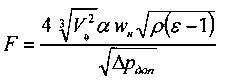
1. Взрывозащитная разрушающаяся конструкция для ограждения особо опасных производственных объектов, содержащая железобетонные панели размером 6000×1800 мм, панель состоит из разрушающейся и неразрушающейся частей, при этом неразрушающаяся часть выполнена в виде несущих ребер, размещенных по контуру разрушающейся части, а разрушающаяся часть выполнена в виде, по крайней мере, двух коаксиально расположенных углублений в стене здания, одна из которых, внешняя образована плоскостями правильной четырехугольной усеченной пирамиды с прямоугольным основанием, а другая - внутренняя, представляет собой две наклонные поверхности, соединенные ребром, с образованием паза, при этом толщина стены от ребра до внешней поверхности ограждения здания должна быть не менее δ=20 мм, при этом, при воздействии ударной, взрывной нагрузки этот участок стены может быть разделен на отдельные части, а площадь разрушающейся части проемов вычисляется по формуле:,где Vo - свободный объем помещения, м; α - коэффициент интенсификации горения; w- нормальная скорость распространения пламени в смеси стехиометрического состава, м/с; ρ - плотность газов, истекающих из проемов, кг/м; ε - степень теплового расширения продуктов сгорания; Δр- допускаемое давление в помещении (5 кПа), а напротив разрушающейся части, с внешней стороны ограждения здания, расположен защитный экран из материала повышенной прочности, например бронированного материала, который закреплен на, по крайней мере, трех горизонтально расположенных и перпендикулярных ограждению здания, стержнях, по концам которых закреплены диски, и которые проходят сквозь отверстия в защитном экране, причем диски, расположенные с1. Explosion-proof collapsible structure for enclosing particularly hazardous industrial facilities, containing reinforced concrete panels of 6000 × 1800 mm in size, the panel consists of collapsing and non-collapsing parts, while the non-collapsing part is made in the form of load-bearing ribs placed along the contour of the collapsing part, and the collapsing part is made in at least two coaxially located recesses in the wall of the building, one of which, the outer one is formed by the planes of a regular quadrangular truncated pyramid with a rectangular the base, and the other internal, is two inclined surfaces connected by a rib to form a groove, while the wall thickness from the rib to the outer surface of the building enclosure should be at least δ = 20 mm, while under the influence of shock, explosive load this wall section can be divided into separate parts, and the area of the collapsing part of the openings is calculated by the formula:, where Vo is the free volume of the room, m; α is the coefficient of intensification of combustion; w is the normal flame propagation velocity in a mixture of stoichiometric composition, m / s; ρ is the density of gases flowing from the openings, kg / m; ε is the degree of thermal expansion of the combustion products; Δp is the permissible pressure in the room (5 kPa), and on the contrary to the collapsing part, on the outside of the building’s fence, there is a protective shield made of high-strength material, such as armored material, which is fixed to at least three horizontally located and perpendicular to the building’s fencing, rods, at the ends of which the disks are fixed, and which pass through the holes in the protective shield, the disks located with
Claims (5)
Priority Applications (1)
| Application Number | Priority Date | Filing Date | Title |
|---|---|---|---|
| RU2015114669A RU2658955C2 (en) | 2015-04-20 | 2015-04-20 | Explosion protective structure for the extremely hazardous production facilities |
Applications Claiming Priority (1)
| Application Number | Priority Date | Filing Date | Title |
|---|---|---|---|
| RU2015114669A RU2658955C2 (en) | 2015-04-20 | 2015-04-20 | Explosion protective structure for the extremely hazardous production facilities |
Publications (3)
| Publication Number | Publication Date |
|---|---|
| RU2015114669A true RU2015114669A (en) | 2016-11-10 |
| RU2015114669A3 RU2015114669A3 (en) | 2018-03-14 |
| RU2658955C2 RU2658955C2 (en) | 2018-06-26 |
Family
ID=57267709
Family Applications (1)
| Application Number | Title | Priority Date | Filing Date |
|---|---|---|---|
| RU2015114669A RU2658955C2 (en) | 2015-04-20 | 2015-04-20 | Explosion protective structure for the extremely hazardous production facilities |
Country Status (1)
| Country | Link |
|---|---|
| RU (1) | RU2658955C2 (en) |
Family Cites Families (4)
| Publication number | Priority date | Publication date | Assignee | Title |
|---|---|---|---|---|
| SU501170A1 (en) * | 1974-01-25 | 1976-01-30 | Кузбасский Политехнический Институт | Mine blast-resistant jumper |
| DE69832506T2 (en) * | 1997-09-26 | 2006-08-10 | Vistek Inc., Phoenix | DEVICE FOR INSULATING MICROSPHERE |
| RU2285835C1 (en) * | 2005-04-25 | 2006-10-20 | Олег Савельевич Кочетов | Disk-type vibration isolator |
| RU2545196C1 (en) * | 2014-01-27 | 2015-03-27 | Олег Савельевич Кочетов | Explosion-proof destructive construction for fencing specially hazardous industrial facilities |
-
2015
- 2015-04-20 RU RU2015114669A patent/RU2658955C2/en active
Also Published As
| Publication number | Publication date |
|---|---|
| RU2015114669A3 (en) | 2018-03-14 |
| RU2658955C2 (en) | 2018-06-26 |
Similar Documents
| Publication | Publication Date | Title |
|---|---|---|
| RU131757U1 (en) | EXPLOSIVE DESTRUCTIVE DESTRUCTIVE BUILDING PROTECTION DESIGN | |
| RU148516U1 (en) | EXPLOSIVE DESTRUCTIVE DESTRUCTING BUILDING Fencing | |
| RU2012135100A (en) | FASTING DESTRUCTIVE BUILDING PROTECTION DESIGN | |
| RU2558822C1 (en) | Explosion-proof damaged structure of building enclosure | |
| RU2015114669A (en) | EXPLOSIVE DESTRUCTIVE DESTRUCTIVE DESIGN FOR PROTECTING ESPECIALLY HAZARDOUS PRODUCTION FACILITIES | |
| RU2522841C1 (en) | Explosion-proof destructive construction of building guards | |
| RU2015114671A (en) | EXPLOSIVE DESTRUCTIVE DESTRUCTIVE DESIGN FOR PROTECTING ESPECIALLY HAZARDOUS PRODUCTION FACILITIES | |
| RU2015114667A (en) | EXPLOSIVE DESTRUCTIVE DESTRUCTIVE DESIGN FOR PROTECTING ESPECIALLY HAZARDOUS PRODUCTION FACILITIES | |
| RU2015114672A (en) | EXPLOSIVE DESTRUCTIVE DESTRUCTIVE DESIGN FOR PROTECTING ESPECIALLY HAZARDOUS PRODUCTION FACILITIES | |
| RU2646254C1 (en) | Buildings enclosure explosion-proof breakable structure | |
| RU2545196C1 (en) | Explosion-proof destructive construction for fencing specially hazardous industrial facilities | |
| RU2522842C1 (en) | Explosion-proof destructive construction of building guards | |
| RU2606469C1 (en) | Buildings enclosure explosion-proof breakable structure | |
| RU2015115772A (en) | FASTING DESTRUCTIVE BUILDING PROTECTION DESIGN | |
| RU2015130867A (en) | EXPLOSIVE DESTRUCTIVE DESTRUCTIVE BUILDING PROTECTION DESIGN | |
| JP6105101B2 (en) | Ceiling structure | |
| RU2015133173A (en) | KETCHET SAFETY DESTRUCTIVE DESTRUCTIVE DESIGN FOR BUILDINGS | |
| RU2572868C1 (en) | Explosion-proof safety collapsible guard of buildings | |
| RU2015128347A (en) | EXPLOSIVE DESTRUCTIVE DESTRUCTIVE BUILDING PROTECTION DESIGN | |
| RU2017117444A (en) | SAFETY DESTRUCTIVE DESTRUCTIVE DESIGN | |
| RU2015130871A (en) | EXPLOSIVE DESTRUCTIVE DESTRUCTIVE DESIGN OF THE KOCHETOV BUILDING PROTECTION | |
| RU2015144520A (en) | FASTING DESTRUCTIVE BUILDING PROTECTION DESIGN | |
| RU2015133175A (en) | KOCHETOV SAFETY DESIGN WITH PROTECTIVE SCREEN | |
| RU2015130869A (en) | EXPLOSIVE DESTRUCTIVE DESTRUCTIVE BUILDING PROTECTION DESIGN | |
| RU2658943C2 (en) | Buildings explosion-proof enclosure destructible part protective shield disc elastic elements safety package |
Legal Events
| Date | Code | Title | Description |
|---|---|---|---|
| HE9A | Changing address for correspondence with an applicant |