RU2013866C1 - Remote control radio line - Google Patents
Remote control radio line Download PDFInfo
- Publication number
- RU2013866C1 RU2013866C1 SU4904595A RU2013866C1 RU 2013866 C1 RU2013866 C1 RU 2013866C1 SU 4904595 A SU4904595 A SU 4904595A RU 2013866 C1 RU2013866 C1 RU 2013866C1
- Authority
- RU
- Russia
- Prior art keywords
- output
- input
- inputs
- frequency
- outputs
- Prior art date
Links
Images
Landscapes
- Monitoring And Testing Of Transmission In General (AREA)
- Mobile Radio Communication Systems (AREA)
Abstract
Description
Изобретение относится к технике связи и предназначено для дистанционного управления передатчиками на передающем радиоцентре в условиях воздействия внутрисистемных и внешних помех. The invention relates to communication technology and is intended for remote control of transmitters at a transmitting radio center under conditions of internal and external interference.
Цель изобретения - повышение помехоустойчивости за счет анализа электромагнитной обстановки на передающем радиоцентре и динамической предварительной отбраковки частот радиолинии дистанционного управления (РЛДУ), на которых ожидается внутрисистемная помеха. The purpose of the invention is to increase the noise immunity due to the analysis of the electromagnetic environment at the transmitting radio center and the dynamic preliminary rejection of frequencies of the radio remote control line (RLDU), on which an intrasystem interference is expected.
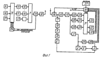
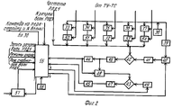
На фиг. 1 показана структурная электрическая схема предложенной радиолинии; на фиг. 2 - схема анализатора внутрисистемных помех. In FIG. 1 shows a structural electrical diagram of the proposed radio line; in FIG. 2 is a diagram of an intra-system interference analyzer.
Радиолиния содержит анализатор 1 внутрисистемных помех, сумматор 2, фильтр 3 контрольной частоты, детектор 4, первый пороговый блок 5, элемент ИЛИ 6, нормализатор 7 уровня, фильтр 8 низкой частоты, второй пороговый блок 9, детектор 10 огибающей, пиковый детектор 11, частотный демодулятор 12, усилитель-ограничитель 13, источник 14 информации, преобразователь 15 частоты, канальный фильтр 16, синтезатор 17, усилитель 18 мощности, линейный тракт 19, канальный фильтр 20, преобразователь 21 частоты, приемник 22 информации, генератор 23 псевдослучайной последовательности (ПСП), частотный модулятор 24, частотный демодулятор 25, анализатор 26 ПСП, генератор 27 ПСП, коммутатор 28, блок 29 управления, блок 30 управления приемной части, коммутатор 31, анализатор 32 ПСП, делители 33-37 с переменным коэффициентом деления, опорный кварцевый генератор 38, умножитель 39, делитель 40 с переменным коэффициентом деления, фильтр 41 низкой частоты 41, смесители 42, 43, пороговые блоки 44, 45, полосовые фильтры 46, 47, электронный ключ 48, генератор 49 синусоидальных сигналов, аттенюаторы 50-54, запоминающий блок 55, генератор 56 синхроимпульсов и блок 57 сравнения. The radio link contains an intra-system interference analyzer 1, an adder 2, a control frequency filter 3, a detector 4, a first threshold unit 5, an OR 6 element, a level 7 normalizer, a low-pass filter 8, a second threshold unit 9, an envelope detector 10, a peak detector 11, a frequency detector demodulator 12, limiter amplifier 13,
Работа РЛДУ заключается в том, что при перестройке своих передатчиков и появлении на частоте приема многоканальной линии связи помехи осуществляется анализ и при превышении допустимого уровня подается команда на перестройку передатчика приемного радиоцентра и приемника многоканальной линии связи передающего радиоцентра. Скорость анализа помеховой обстановки такова, что за время настройки усилителей мощности передатчиков декаметрового диапазона РЛДУ "подготавливает" качественный ствол многоканальной линии связи. The operation of the RLDU is that when you rebuild your transmitters and appear at the receive frequency of the multi-channel communication line, an analysis is performed and if the acceptable level is exceeded, a command is sent to rebuild the transmitter of the receiving radio center and the receiver of the multi-channel communication line of the transmitting radio center. The rate of analysis of the interference environment is such that during the setup of the power amplifiers of the decameter band transmitters, the RLDU "prepares" a high-quality trunk of a multi-channel communication line.
Этот анализ предусмотрен для повышения коэффициента исправного действия РЛДУ за счет динамической отбраковки "забитых" частот и является дополнением к контролю, описанному в устройстве-прототипе. This analysis is intended to increase the operational efficiency coefficient of the RLDU due to the dynamic rejection of "clogged" frequencies and is an addition to the control described in the prototype device.
Принцип работы устройства контроля многоканальной линии связи состоит в следующем. При вхождении в связь в начальный момент времени передается псевдослучайная последовательность от генератора 23 ПСП передающей части, которая также подается на блок 29 управления передающей части многооканальной линии связи (МКЛС). В приемной части МКЛС псевдослучайная последовательность после линейного тракта 19, усилителя-ограничителя 13, частотного демодулятора 12 выделяется фильтром 3 контрольной частоты, демодулируется и подается на анализатор 26 ПСП, где постоянно осуществляется анализ контрольного сигнала по принципу "свой-чужой". Сигнал с выхода анализатора 32 ПСП подается на вход элемента ИЛИ 6, а с второго выхода анализатора псевдослучайная последовательность подается на первый вход блока 30 управления. Начало такта ПСП служит командой для подготовки к работе блоков 29, 30 и постановки в исходное положение коммутаторов 28, 31 каналов. Передаваемая информация от источника 14 информации поступает на коммутатор 28, где распределяется по каналам связи. После коммутатора каналов информация поступает на преобразователи 15 частоты, затем на канальные фильтры 16 и на сумматор 2 многоканальной линии связи, на выходе которого образуется групповой сигнал, который подается в синтезатор 17, где осуществляется частотная модуляция и последующее усиление группового сигнала усилителя 18 и излучается антенной. Псевдослучайная последовательность от генератора 27 передается по одному из свободных каналов, предоставляемым коммутатором 28 каналов. The principle of operation of the control device multichannel communication line is as follows. Upon entering into communication at the initial time, a pseudo-random sequence is transmitted from the transmitting
В приемной части до коммутатора 31 каналов ПСП проходит тот же путь, что и оперативная информация. После коммутатора 31 псевдослучайная последовательность поступает на анализатор 32 ПСП, где происходит анализ ПСП и определяется качество каналов. In the receiving part, up to the
Сведения о состоянии каналов передаются на блок 30 управления, который выдает команду на свой коммутатор 31 каналов и по обратному каналу на блок 29 управления передающей части - исключить тот или иной канал или оставить его для передачи оперативной информации. Коммутаторы 28 и 31 каналов как приемной, так и передающей частей осуществляется попеременное синхронное подключение каждого канала к генератору 27 ПСП N2 и к анализатору 32 ПСП N2 в приемной части. Синхронность переключения каналов обусловлена тем, что ПСП имеет конечную длину и повторяется генератором 37 ПСП через установленный промежуток времени, определяемый частотой контроля. Структура ПСП N2 известна блоку управления приемной части и конец каждого такта ПСП N2 служит командой для блока управления, чтобы выработать сигнал на переключение коммутатору. Этот же сигнал по обратному каналу передается на блок 29 управления передающей части. В анализаторе 32 ПСП N2 происходит сравнение принятой ПСП с записанной в памяти анализатора, и если окажется, что количество неправильно принятых символов ПСП больше установленного, выдается сигнал на блок 30 управления. Блок 30 управления приемной части выдает команду на коммутатор 31 приемной части и по обратному каналу на блок 29 управления передающей части об исключении данного канала для передачи информации. Если окажется, что количество ошибок не превышает допустимого, то с анализатора 32 ПСП поступает сигнал на блок 30 управления, с которого выдается команда на коммутатор 31 и по обратному каналу на блок 29 управления передающей части о включении этого канала для передачи оперативной информации. Блок 29 управления передающей части в зависимости от того, какая команда поступает с обратного канала, включает или исключает каналы для передачи оперативной информации в коммутатор 28. Information about the state of the channels is transmitted to the
Если количество бракованных каналов окажется таким, что станет невозможной передача информации по требуемому числу индивидуальных каналов, то с блока 30 управления приемной части выдается сигнал перестройки приемной и передающей частей многоканальной линии связи на другую частоту. If the number of defective channels turns out to be such that it becomes impossible to transmit information on the required number of individual channels, then from the receiving unit control unit 30 a signal is received for tuning the receiving and transmitting parts of the multi-channel communication line to another frequency.
Принцип работы устройства анализа внутрисистемных помех состоит в следующем (см. фиг. 2). При настройке передатчиков в момент готовности возбудителей на делители 33-37 подается код частоты передатчиков и передатчика РЛДУ. Они делят частоту кварцевого генератора 38 и будут иметь на своих выходах частоты передатчиков. Информация об уровне мощности и дальностях до передатчиков устанавливается на аттенюаторах. Все эти частоты подаются на смеситель 42, где смешиваются в различных комбинациях они сами и их гармоники. Так как генератор с очень короткими (остроконечными) импульсами с большим набором гармоник, т. е. мы анализируем все гармоники этих частот и их комбинации. The principle of operation of the device for analysis of intra-system interference is as follows (see Fig. 2). When setting up the transmitters at the moment the pathogens are ready, the frequency code of the transmitters and the RLDU transmitter is supplied to the dividers 33-37. They divide the frequency of the
На другой вход смесителя подается подставка от делителя 40, который делит частоту кварцевого генератора, ибо подставки отличаются от частоты генератора 38. Фильтр 41 не пропускает гармоники от частоты делителя, так как они оказывают мешающее действие. Частота делителя 40 устанавливается запоминающим блоком 55. At the other input of the mixer, a stand is supplied from the
Фильтр 46 выделяет все комбинации в полосе 1 мГц, т. е. все возможные комбинации, которые действуют на пакеты частот РЛДУ. Пороговое устройство срабатывает, если на выходе фильтра присутствуют мешающие комбинации, и не срабатывает, если они будут отсутствовать. Если пороговое устройство не сработало, на его выходе находится "0", который дает команду в запоминающий блок 55 о том, что весь пакет чист от мешающей помехи частот работающих передатчиков, дает команду на закрытие электронного ключа 48 и не соединяет выход фильтра 46 со смесителем 43. Т. е. в этом случае частоты в пакете (номера волн) не анализируются, а в блок 55 записывает весь пакет.
Если в пакете будет хоть одна мешающая частота, то пороговый блок срабатывает, на его выходе появляется "1", которая открывает электронный ключ 48 и анализируются пять частот в пакете аналогично. Полоса пропускания фильтра 48200 кГц. При появлении "0" на выходе порогового блока 45 в ячейке запоминающего блока записывается информация о свободных частотах. После анализа одного пакета анализируется следующий по команде от блока 55 и так пока не проанализируются все пакеты, в которых находятся разрешенные волны РЛДУ. Далее выдается сигнал на блок 30 (см. фиг. 1) для перестройки РЛДУ на другую свободную от помех частоту. If there is at least one interfering frequency in the packet, the threshold block is triggered, "1" appears on its output, which opens the
Полоса пропускания фильтра 46 должна быть ниже частот 1,5-60 мГц работающих передатчиков. В противном случае могут получиться комбинации, которые будут пропускаться фильтром но не будут оказывать влияние на работу РЛДУ. По той же причине полоса пропускания фильтра 47 должна быть ниже частот, пропущенных фильтром 46. The passband of the
Таким образом, предложенная РЛДУ позволит повысить коэффициент исправного действия при воздействии внутрисистемных случайных помех от собственных передатчиков за счет динамической предварительной обстановки "занятых" частот. Thus, the proposed RLDU will make it possible to increase the coefficient of serviceability under the influence of intrasystem random interference from own transmitters due to the dynamic preliminary situation of “occupied” frequencies.
Это приводит и к существенному увеличению времени безотказной работы радиоканала, и к повышению эффективности радиосвязи. This leads to a significant increase in the uptime of the radio channel, and to an increase in the efficiency of radio communications.
Claims (1)
Priority Applications (1)
| Application Number | Priority Date | Filing Date | Title |
|---|---|---|---|
| SU4904595 RU2013866C1 (en) | 1991-01-22 | 1991-01-22 | Remote control radio line |
Applications Claiming Priority (1)
| Application Number | Priority Date | Filing Date | Title |
|---|---|---|---|
| SU4904595 RU2013866C1 (en) | 1991-01-22 | 1991-01-22 | Remote control radio line |
Publications (1)
| Publication Number | Publication Date |
|---|---|
| RU2013866C1 true RU2013866C1 (en) | 1994-05-30 |
Family
ID=21556782
Family Applications (1)
| Application Number | Title | Priority Date | Filing Date |
|---|---|---|---|
| SU4904595 RU2013866C1 (en) | 1991-01-22 | 1991-01-22 | Remote control radio line |
Country Status (1)
| Country | Link |
|---|---|
| RU (1) | RU2013866C1 (en) |
-
1991
- 1991-01-22 RU SU4904595 patent/RU2013866C1/en active
Similar Documents
| Publication | Publication Date | Title |
|---|---|---|
| US4843638A (en) | Receiver for frequency hopped signals | |
| US3160813A (en) | Tropospheric radio communication system | |
| US4357709A (en) | Apparatus for regenerating signals within a frequency band | |
| RU2013866C1 (en) | Remote control radio line | |
| JPH02209025A (en) | Radio communication equipment | |
| US3736512A (en) | Non-interfering on-line communication receiver test system | |
| US2509716A (en) | Arrangement for secret radio telephony | |
| RU2178952C1 (en) | System for transmitting and receiving modulated signals over power supply mains | |
| RU2080739C1 (en) | Receiver | |
| RU1788584C (en) | Device for automatic search of radio communication channels | |
| RU2002100954A (en) | A device for generating response interference to radar stations | |
| RU95116780A (en) | RADIO STATION | |
| RU2001122342A (en) | Device for interfering with radar stations | |
| RU2293439C2 (en) | Receiver of radio-impulse signals with frequency-time encoding | |
| SU1450116A2 (en) | Device for monitoring multichannel communication line | |
| JP2630889B2 (en) | Radio propagation delay measurement equipment | |
| SU1050128A1 (en) | Device for transmitting frequency-time telecontrol signals | |
| SU767984A1 (en) | Device for selecting optimum communication frequencies | |
| JPH05130055A (en) | Reception signal power alarm circuit | |
| SU403083A1 (en) | METHOD OF TRANSMISSION-RECEPTION OF RADIOTELEPHONE SIGNALS WITH TEMPORARY DIFFERENCE | |
| SU1367167A1 (en) | Device for selection of pulses in receiver for multichannel asynchronous communication system | |
| SU771901A1 (en) | Device for receiving broad-band signals with linear frequency modulation | |
| SU708531A1 (en) | Device for receiving frequency-phase manipulated signals | |
| SU1192146A1 (en) | Device for checking serviceability of superheterodyne receiver | |
| RU1790041C (en) | Device for transmission of multifrequency signals |