RU2013503C1 - Joint of tubular sections - Google Patents
Joint of tubular sections Download PDFInfo
- Publication number
- RU2013503C1 RU2013503C1 SU5010035A RU2013503C1 RU 2013503 C1 RU2013503 C1 RU 2013503C1 SU 5010035 A SU5010035 A SU 5010035A RU 2013503 C1 RU2013503 C1 RU 2013503C1
- Authority
- RU
- Russia
- Prior art keywords
- holes
- ribs
- connection
- joint
- profiles
- Prior art date
Links
- 238000010276 construction Methods 0.000 abstract 1
- 239000000126 substance Substances 0.000 abstract 1
- 238000000034 method Methods 0.000 description 4
- 238000000576 coating method Methods 0.000 description 2
- 238000009434 installation Methods 0.000 description 2
- 238000005452 bending Methods 0.000 description 1
- 230000015572 biosynthetic process Effects 0.000 description 1
- 150000001875 compounds Chemical class 0.000 description 1
- 238000010586 diagram Methods 0.000 description 1
- 239000011521 glass Substances 0.000 description 1
- 230000005484 gravity Effects 0.000 description 1
- 238000004519 manufacturing process Methods 0.000 description 1
- 239000002184 metal Substances 0.000 description 1
Images
Landscapes
- Mutual Connection Of Rods And Tubes (AREA)
- Dowels (AREA)
- Separation Using Semi-Permeable Membranes (AREA)
- Furniture Connections (AREA)
Abstract
Description
Изобретение относится к узлам для быстрого и функционального соединения трубчатых профилей, в частности, при выполнении различного рода покрытий, например туннелей, портальных рам, застекленных крыш или куполов жилых и промышленных зданий. The invention relates to nodes for quick and functional connection of tubular profiles, in particular, when performing various kinds of coatings, for example tunnels, portal frames, glazed roofs or domes of residential and industrial buildings.
В настоящее время для соединения трубчатых профилей, образующих конструкцию, на которую будут устанавливаться листы или предварительно отформованные модули, изготовленные из пластмассы или стекла, образуя тем самым различного типа покрытия, использующиеся в жилищном и промышленном строительствах, существует несколько решений или способов их реализации, например, установка пластин или различных соединительных элементов между двумя профилями и последующее закрепление всех элементов винтами или проходными болтами. Однако использовавшиеся до настоящего времени способы обладали рядом недостатков как с практической, так и эстетической точек зрения, а именно: любое соединение, будь оно прямое, под углом 45о, криволинейное или крестообразное требует собственного решения или способа; все различные элементы, формирующие такие соединительные системы, имеют очень толстые секции, в результате чего как только конструкция собрана, то узловые точки могут противостоять как скручивающему, так и изгибающему моментам; а также на видимых деталях конструкции видны болты, использующиеся для соединения.Currently, for joining tubular profiles forming a structure on which sheets or preformed modules made of plastic or glass will be installed, thereby forming various types of coatings used in residential and industrial buildings, there are several solutions or methods for their implementation, for example installation of plates or various connecting elements between two profiles and the subsequent fastening of all elements with screws or through-bolts. However, hitherto used methods had several disadvantages both from the practical and aesthetic points of view, namely any compound, whether it is straight, at an angle of 45 °, curved or cruciform requires its own decision or the process; all the various elements forming such connecting systems have very thick sections, as a result of which, as soon as the structure is assembled, the nodal points can withstand both twisting and bending moments; and also on the visible details of the structure, the bolts used for the connection are visible.
Целью изобретения является создание предварительно отформованной детали или связи, состоящей из корпуса, снабженного ребрами, на которых выполнены седло под палец и соответствующие отверстия для крепления соединяемых трубчатых профилей, устраняя тем самым избыточный удельный вес систем, использовавшихся до настоящего времени, за счет одновременного сохранения обеих важных характеристик сопротивляемости и затянутости соединения и существенных экономических преимуществ, обусловленных тем, что с помощью только одного типа соединения, удобно собранного, удовлетворяются все потребности в соединениях, а также улучшается эстетический вид, поскольку все выступающие болты, использовавшиеся до настоящего времени, отсутствуют. The aim of the invention is the creation of a pre-molded part or connection, consisting of a housing provided with ribs on which a saddle is provided for the finger and corresponding holes for fastening the connected tubular profiles, thereby eliminating the excess specific gravity of the systems used to date, by simultaneously saving both important characteristics of the resistance and tightness of the connection and significant economic advantages due to the fact that using only one type of connection , conveniently assembled, all the needs for joints are satisfied, and the aesthetic appearance is improved, since all the protruding bolts that have been used to date are absent.
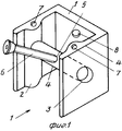
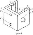
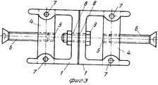
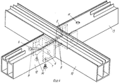
На фиг. 1, 2 показаны передняя и задняя стороны предварительно отформованного С-образного элемента; на фиг. 3 - узел из предварительно установленных двух профилей в прямое или криволинейное соединение, вид сверху; на фиг. 4 - два элемента, правильно установленные относительно профилей при образовании крестообразного соединения. In FIG. 1, 2 show the front and back sides of a preformed C-shaped member; in FIG. 3 - a node from a pre-installed two profiles in a direct or curved connection, top view; in FIG. 4 - two elements correctly installed relative to the profiles during the formation of a cruciform connection.
Предлагаемый узел образован предварительно отформованным элементом, снабженным ребрами 2, в которых выполнены отверстия 3 для приема пальца 4, имеющего резьбовое отверстие 5, предназначенное для зажимного винта 6. Ребра 2 служат для увеличения площади, на которой выполняются отверстия 3 и резьбовые отверстия 7, а также для повышения сопротивляемости узла. На задней стенке узла имеются сквозные отверстия 8, предназначенные под болты 9. The proposed site is formed by a preformed element provided with
На фиг. 4 показана схема сборки узла, при этом соединение металлических профилей в крестообразное соединение осуществлено следующим образом: на профиле 10 выпольнены сквозные отверстия, соединенные с отверстиями 8, для прохождения болтов 9. В этом месте два узла закреплены на профиле 10 с помощью болтов 9, а после этого винты 6 вставляются через отверстия 11, предварительно выполненные на профилях 12 и 13 для закрепления в отверстиях 5 пальцев 4 благодаря тому, что отверстия 11 имеют не ту же ось, что отверстия 5. Винты 6 помимо крепления узлов к профилям 12 и 13 выполняют также роль соединительных тяг, гарантирующих соединение различных деталей и хорошую затягиваемость всего соединения. После этого в отверстия 7, выполненные в ребрах 2 узла, вставляются винты 14. In FIG. Figure 4 shows the assembly diagram of the assembly, the connection of metal profiles in a cruciform connection is carried out as follows: on the
При простом соединении прямого или криволинейного профилей достаточно соединить сначала задние стенки двух С-образных элементов с помощью болтов 9 (фиг. 3) соблюдая вышеупомянутые сборочные операции. With a simple connection of a straight or curved profile, it is enough to first connect the rear walls of two C-shaped elements with the help of bolts 9 (Fig. 3) observing the above assembly operations.
Преимущества данного решения очевидны: независимо от того, один ли он, или спарен, или в различном сочетании - он обеспечивает любой тип соединения трубчатых профилей, а именно крестообразный, прямой, криволинейный или под углом 45о, тем самым заменяя все различные решения или способы, применявшиеся до настоящего времени, делая возможным снижение стоимости и времени производства и сборки.The advantages of this solution are obvious: regardless of whether it is single, or paired, or in a different combination, it provides any type of connection of tubular profiles, namely, cruciform, straight, curved or at an angle of 45 about , thereby replacing all the different solutions or methods applied to date, making it possible to reduce the cost and time of production and assembly.
Кроме того предлагаемый узел после его правильной установки на трубчатых профилях гарантирует получение жесткой конструкции, ограничивая любые виды перемещений, которым подвергается соединение, обеспечивает хороший внешний вид, поскольку устранены все выступающие болты, которые использовались до настоящего времени. In addition, the proposed site after its proper installation on the tubular profiles ensures a rigid structure, limiting any kind of movement that the connection is subjected to, provides a good appearance, since all protruding bolts that have been used to date have been eliminated.
Более того палец, являющийся шарнирным пальцем, позволяет устанавливать винт под любым наклоном, облегчая операцию крепления. Moreover, the finger, which is an articulated finger, allows you to set the screw at any angle, facilitating the fastening operation.
Claims (2)
Applications Claiming Priority (2)
| Application Number | Priority Date | Filing Date | Title |
|---|---|---|---|
| IT9030714 | 1990-10-26 | ||
| IT3071490U IT222954Z2 (en) | 1990-10-26 | 1990-10-26 | PREFORMED JOINT |
Publications (1)
| Publication Number | Publication Date |
|---|---|
| RU2013503C1 true RU2013503C1 (en) | 1994-05-30 |
Family
ID=11231299
Family Applications (1)
| Application Number | Title | Priority Date | Filing Date |
|---|---|---|---|
| SU5010035 RU2013503C1 (en) | 1990-10-26 | 1991-10-25 | Joint of tubular sections |
Country Status (5)
| Country | Link |
|---|---|
| CS (1) | CS325291A3 (en) |
| IT (1) | IT222954Z2 (en) |
| PT (1) | PT8377U (en) |
| RU (1) | RU2013503C1 (en) |
| TR (1) | TR26487A (en) |
Cited By (2)
| Publication number | Priority date | Publication date | Assignee | Title |
|---|---|---|---|---|
| RU2373344C1 (en) * | 2008-08-13 | 2009-11-20 | Федеральное государственное образовательное учреждение высшего профессионального образования "Сибирский федеральный университет" | Unit for connection of tubular section bars in trihedral girder |
| RU2423582C1 (en) * | 2010-03-25 | 2011-07-10 | Федеральное Государственное Автономное Образовательное Учреждение Высшего Профессионального Образования "Сибирский Федеральный Университет" | Unit to connect tubes |
Family Cites Families (1)
| Publication number | Priority date | Publication date | Assignee | Title |
|---|---|---|---|---|
| FR2593862B1 (en) * | 1986-02-04 | 1991-07-05 | Technal France | LOCKING PIECE FOR ANGLE JOINING DEVICES OF A HOLLOW PROFILE WITH ANOTHER ELEMENT AND ASSEMBLING DEVICES INCLUDING THIS LOCKING PIECE |
-
1990
- 1990-10-26 IT IT3071490U patent/IT222954Z2/en active IP Right Grant
-
1991
- 1991-10-21 PT PT837791U patent/PT8377U/en not_active IP Right Cessation
- 1991-10-25 CS CS913252A patent/CS325291A3/en unknown
- 1991-10-25 TR TR100291A patent/TR26487A/en unknown
- 1991-10-25 RU SU5010035 patent/RU2013503C1/en active
Cited By (2)
| Publication number | Priority date | Publication date | Assignee | Title |
|---|---|---|---|---|
| RU2373344C1 (en) * | 2008-08-13 | 2009-11-20 | Федеральное государственное образовательное учреждение высшего профессионального образования "Сибирский федеральный университет" | Unit for connection of tubular section bars in trihedral girder |
| RU2423582C1 (en) * | 2010-03-25 | 2011-07-10 | Федеральное Государственное Автономное Образовательное Учреждение Высшего Профессионального Образования "Сибирский Федеральный Университет" | Unit to connect tubes |
Also Published As
| Publication number | Publication date |
|---|---|
| TR26487A (en) | 1995-03-15 |
| IT222954Z2 (en) | 1995-05-12 |
| PT8377T (en) | 1992-05-29 |
| CS325291A3 (en) | 1992-05-13 |
| PT8377U (en) | 1994-11-30 |
| IT9030714V0 (en) | 1990-10-26 |
| IT9030714U1 (en) | 1992-04-26 |
Similar Documents
| Publication | Publication Date | Title |
|---|---|---|
| US5048254A (en) | Prefabricated building panel | |
| CA2199770A1 (en) | Wall panel assembly | |
| RU2013503C1 (en) | Joint of tubular sections | |
| US4817349A (en) | Apparatus for heating, ventilating, cooling and regulating the temperature of rooms of a building | |
| US4293122A (en) | Pipe railing system | |
| RU2041325C1 (en) | Connection unit for tubular profiles | |
| EP0482667A1 (en) | Preformed joint | |
| CN116335290A (en) | An Integrated Node Technology for Single Section Bars | |
| CN220790412U (en) | Assembled component of stone unit | |
| KR100340088B1 (en) | Ceiling Panel Fixture | |
| KR100473681B1 (en) | Jointing device of solar collector for steel house | |
| KR200322797Y1 (en) | Bracket for join on metal panel | |
| CN219732346U (en) | Building roof and building wallboard connection structure | |
| CN217759450U (en) | Glass curtain wall high-speed joint design structure | |
| CN116657798B (en) | Aluminum veneer curtain wall, assembled aluminum veneer curtain wall system and installation method | |
| CN211647769U (en) | Wall brace connection structure | |
| CN216810518U (en) | Simple installation, pleasing to eye articulate aluminum plate structural system that cracks | |
| CN213390555U (en) | Precast beam that resistance to compression effect is strong | |
| CN216516266U (en) | Fireproof building energy-saving glass assembly | |
| RU94045583A (en) | Butt joining of wall panels with column | |
| KR860002598Y1 (en) | Prefab | |
| JP2517004Y2 (en) | Roof structure | |
| KR200193230Y1 (en) | Connecting device for dome-styled skylights | |
| CZ224893A3 (en) | Set of structural element for making combined metal and wood sections | |
| JPS5811851Y2 (en) | Connecting fittings in prefabricated houses |