RU201218U1 - VIBRATION MECHANISM - Google Patents
VIBRATION MECHANISM Download PDFInfo
- Publication number
- RU201218U1 RU201218U1 RU2019135753U RU2019135753U RU201218U1 RU 201218 U1 RU201218 U1 RU 201218U1 RU 2019135753 U RU2019135753 U RU 2019135753U RU 2019135753 U RU2019135753 U RU 2019135753U RU 201218 U1 RU201218 U1 RU 201218U1
- Authority
- RU
- Russia
- Prior art keywords
- elastic element
- additional elastic
- vibration
- deformation
- vibration isolating
- Prior art date
Links
Images


Classifications
-
- F—MECHANICAL ENGINEERING; LIGHTING; HEATING; WEAPONS; BLASTING
- F16—ENGINEERING ELEMENTS AND UNITS; GENERAL MEASURES FOR PRODUCING AND MAINTAINING EFFECTIVE FUNCTIONING OF MACHINES OR INSTALLATIONS; THERMAL INSULATION IN GENERAL
- F16F—SPRINGS; SHOCK-ABSORBERS; MEANS FOR DAMPING VIBRATION
- F16F15/00—Suppression of vibrations in systems; Means or arrangements for avoiding or reducing out-of-balance forces, e.g. due to motion
- F16F15/02—Suppression of vibrations of non-rotating, e.g. reciprocating systems; Suppression of vibrations of rotating systems by use of members not moving with the rotating systems
Landscapes
- Engineering & Computer Science (AREA)
- General Engineering & Computer Science (AREA)
- Physics & Mathematics (AREA)
- Acoustics & Sound (AREA)
- Aviation & Aerospace Engineering (AREA)
- Mechanical Engineering (AREA)
- Vibration Prevention Devices (AREA)
Abstract
Полезная модель относится к устройствам для виброизоляции систем «человек-машина» и технических систем.Виброизолирующий механизм включает направляющее устройство, содержащее подвижно взаимосвязанные входной, выходной и промежуточный жесткие элементы, основной упругий элемент «положительной» жесткости и дополнительный упругий элемент знакопеременной жесткости, установленный в опорном устройстве с возможностью деформирования, при этом механизм дополнительно снабжен устройством регулирования жесткости при закритическом деформировании «в большом» и величины рабочего хода дополнительного упругого элемента, а дополнительный упругий элемент выполнен в виде пакета взаимосвязанных тонкостенных элементов из композитного материала, обеспечивающего возможность закритического деформирования «в большом» дополнительного упругого элемента при сохранении работоспособности.The utility model relates to devices for vibration isolation of man-machine systems and technical systems. The vibration isolation mechanism includes a guiding device containing movably interconnected input, output and intermediate rigid elements, a main elastic element of "positive" stiffness and an additional elastic element of alternating stiffness installed in support device with the possibility of deformation, while the mechanism is additionally equipped with a device for adjusting the stiffness during postcritical deformation "in large" and the value of the working stroke of the additional elastic element, and the additional elastic element is made in the form of a package of interconnected thin-walled elements made of composite material, which provides the possibility of postcritical deformation "in large »additional elastic element while maintaining performance.
Description
Полезная модель относится к устройствам для виброизоляции и может быть использована для защиты человека, машин и оборудования от широкополосных, особенно инфрачастотных, вибраций и низкочастотного вибрационного шума. Это, например, пилоты и пассажиры, конструкция и оборудование вертолетов, непилотируемые летательные аппараты (наносателлиты, дроны), системы высокоскоростного рельсового транспорта, ускорители заряженных частиц, другие современные и перспективные системы «человек-машина» и технические системы.The utility model relates to devices for vibration isolation and can be used to protect people, machines and equipment from broadband, especially infra-frequency, vibrations and low-frequency vibration noise. These are, for example, pilots and passengers, design and equipment of helicopters, unmanned aerial vehicles (nanosatellites, drones), high-speed rail transport systems, particle accelerators, other modern and promising man-machine systems and technical systems.
Известны виброизолирующие механизмы (Vibration isolation platforms, tables and systems, USA, 2019. - доступно на сайте www.minusk.com). В данных механизмах виброизоляция по вертикали достигается с помощью основного упругого элемента «положительной» жесткости, обеспечивающего несущую способность системы и работающего в параллель с дополнительным упругим элементом «отрицательной» жесткости путем его закритического деформирования «в малом». Поэтому суммарная жесткость обоих упругих элементов в вертикальном направлении движения может быть достаточно малой. Также механизмы снабжены упругими балками для виброизоляции в горизонтальном направлении, последовательно соединенные с упругими элементами вертикального направления. В результате создается возможность получения виброизолирующей системы, имеющей достаточно малые частоты собственных колебаний в вертикальном и горизонтальном направлениях.Known vibration isolation mechanisms (Vibration isolation platforms, tables and systems, USA, 2019. - available at www.minusk.com). In these mechanisms, vertical vibration isolation is achieved with the help of the main elastic element of "positive" stiffness, which provides the bearing capacity of the system and works in parallel with the additional elastic element of "negative" stiffness by means of its postcritical deformation "in small". Therefore, the total stiffness of both elastic elements in the vertical direction of movement can be quite small. Also, the mechanisms are equipped with elastic beams for vibration isolation in the horizontal direction, connected in series with elastic elements of the vertical direction. As a result, it becomes possible to obtain a vibration-isolating system having sufficiently low natural frequencies in the vertical and horizontal directions.
Недостатком данных механизмов является крайне малый рабочий ход при значительных размерах рабочего пространства виброизолирующей системы, что существенно ограничивает область применения механизмов.The disadvantage of these mechanisms is an extremely small working stroke with a significant size of the working space of the vibration isolating system, which significantly limits the scope of the mechanisms.
Наиболее близкой к предлагаемому виброизолирующему механизму является виброзащитная платформа (патент РФ 2093730, МПК F16F 13/00, опубл. 20.10.1997), включающая направляющее устройство, основной упругий элемент, а также дополнительный упругий элемент, выполненный в виде цельного модуля из балок, соединенных по концам и параллельно установленных в опорном устройстве с возможностью продольного натяга, при этом рабочая ось балок совпадает с направлением движения, в котором суммарная жесткость обоих упругих элементов имеет наименьшие значения.The closest to the proposed vibration-isolating mechanism is a vibration-protective platform (RF patent 2093730, IPC F16F 13/00, publ. 20.10.1997), including a guide device, a main elastic element, as well as an additional elastic element made in the form of a solid module from beams connected at the ends and installed in parallel in the support device with the possibility of longitudinal interference, while the working axis of the beams coincides with the direction of motion in which the total stiffness of both elastic elements has the lowest values.
Недостатком данной платформы является невозможность обеспечения эффективной виброизоляции в диапазоне инфрачастот, в частности, 0,5-5 Гц. Кроме того, платформа имеет малый рабочий ход при значительных размерах рабочего пространства виброизолирующей системы, что существенно ограничивает область применения платформы.The disadvantage of this platform is the impossibility of providing effective vibration isolation in the infra-frequency range, in particular, 0.5-5 Hz. In addition, the platform has a small working stroke with a significant working space of the vibration isolating system, which significantly limits the scope of the platform.
Задача полезной модели (технический результат) заключается в создании виброизолирующего механизма, свободного от вышеперечисленных недостатков, при существенном расширении области применения для виброизоляции систем «человек-машина» и технических систем.The task of the utility model (technical result) is to create a vibration-isolating mechanism free from the above disadvantages, while significantly expanding the scope for vibration isolation of man-machine systems and technical systems.
Поставленная задача решается с помощью виброизолирующего механизма, включающего направляющее устройство, содержащее подвижно взаимосвязанные входной, выходной и промежуточный жесткие элементы, основной упругий элемент «положительной» жесткости и дополнительный упругий элемент знакопеременной жесткости, установленный в опорном устройстве с возможностью деформирования, при этом механизм дополнительно снабжен устройством регулирования жесткости при закритическом деформировании «в большом» и величины рабочего хода дополнительного упругого элемента, а дополнительный упругий элемент выполнен в виде пакета взаимосвязанных тонкостенных элементов из композитного материала, обеспечивающего возможность закритического деформирования «в большом» дополнительного упругого элемента при его сохранении работоспособности.The problem is solved with the help of a vibration-isolating mechanism, which includes a guiding device containing movably interconnected input, output and intermediate rigid elements, a main elastic element of "positive" stiffness and an additional elastic element of alternating stiffness installed in the supporting device with the possibility of deformation, while the mechanism is additionally equipped a device for regulating the stiffness during postcritical deformation "in large" and the size of the working stroke of the additional elastic element, and the additional elastic element is made in the form of a package of interconnected thin-walled elements made of composite material, which provides the possibility of postcritical deformation "in the large" of the additional elastic element while maintaining its operability.
Дополнительный упругий элемент из композитного материала обеспечивает возможность получения существенно большей величины закритического деформирования «в большом» данного элемента при сохранении работоспособности, причем без увеличения его эффективного размера, что позволяет существенно увеличить рабочий ход механизма и обеспечить эффективность виброизолирующей системы в расширенном диапазоне частот, включая близкие к нулевым значениям, причем без изменения размеров рабочего пространства системы.An additional elastic element made of composite material makes it possible to obtain a significantly greater value of postcritical deformation "in a large" of a given element while maintaining its operability, and without increasing its effective size, which makes it possible to significantly increase the working stroke of the mechanism and ensure the efficiency of the vibration isolating system in an extended frequency range, including close to zero values, and without changing the size of the system workspace.
Дополнительный упругий элемент может быть выполнен (в зависимости от статической нагрузки системы) в виде одного или нескольких пакетов взаимосвязанных тонкостенных элементов из углеродного волокна.The additional elastic element can be made (depending on the static load of the system) in the form of one or more packages of interconnected thin-walled carbon fiber elements.
Дополнительный упругий элемент может быть выполнен (в зависимости от статической нагрузки) также в виде одного или нескольких пакетов взаимосвязанных тонкостенных элементов из арамидов или пластинчатых конструкций на основе графенов.The additional elastic element can be made (depending on the static load) also in the form of one or more packages of interconnected thin-walled elements made of aramids or plate structures based on graphene.
Использование углеволокна повышает технологичность проектирования компактного дополнительного упругого элемента, обеспечивает возможность закритического деформирования «в большом» в более широком диапазоне, при сохранении работоспособности данного элемента. При определенных проектных условиях, аналогичные свойства дополнительного упругого элемента может обеспечить применение, например, арамидов и пластинчатых конструкций на основе графенов.The use of carbon fiber increases the manufacturability of designing a compact additional elastic element, provides the possibility of postcritical deformation "in a large" in a wider range, while maintaining the performance of this element. Under certain design conditions, similar properties of the additional elastic element can be provided by the use of, for example, aramids and graphene-based plate structures.
Опорный элемент может быть снабжен вкладышами для минимизации трения контактных поверхностей подвижных соединений с дополнительным упругим элементом, что позволяет расширить частотный диапазон эффективности системы, включая частоты, близкие к нулевым значениям.The support element can be provided with bushings to minimize friction of the contact surfaces of the movable joints with an additional elastic element, which makes it possible to expand the frequency range of the system efficiency, including frequencies close to zero values.
Устройство регулирования жесткости и величины рабочего хода дополнительного упругого элемента может быть выполнено, например, в виде передачи винт-гайка, гайка которой подвижно соединена с данным упругим элементом, а винт - с опорным элементом. Также устройство может быть выполнено в виде подвижного штифтового соединения.The device for adjusting the stiffness and the size of the working stroke of the additional elastic element can be made, for example, in the form of a screw-nut transmission, the nut of which is movably connected to the given elastic element, and the screw - to the supporting element. Also, the device can be made in the form of a movable pin connection.
Для снижения уровня низкочастотного (125-1600 Гц) вибрационного шума, который может частично снижать эффективность виброизолирующей системы при относительных перемещениях, сопоставимых с величиной технологических зазоров в подвижных соединениях виброизолирующего механизма, контактные поверхности подвижных соединений могут быть выполнены из композитов на основе сверхвысокомолекулярного полиэтилена с возможностью изменения его трибологических характеристик с помощью полидисперсных наполнителей.To reduce the level of low-frequency (125-1600 Hz) vibration noise, which can partially reduce the effectiveness of the vibration-isolating system with relative displacements comparable to the size of the technological gaps in the movable joints of the vibration-isolating mechanism, the contact surfaces of the moving joints can be made of composites based on ultra-high molecular weight polyethylene with the possibility changing its tribological characteristics with the help of polydisperse fillers.
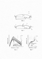
Предлагаемая полезная модель поясняется следующими примерами, где на фиг. 1 показан вариант компоновки опытного образца виброизолирующего механизма, на фиг. 2 - опытный образец дополнительного упругого элемента в виде, например, балки из композита (пакет тонкостенных элементов из углеволокна), в процессе стендовых испытаний, на фиг. 3 - опорный элемент с размещенными в нем дополнительным упругим элементом и устройством регулирования жесткости при закритическом деформировании «в большом» и величины рабочего хода дополнительного упругого элемента, на фиг. 4 - расчетная схема дополнительного упругого элемента при закритическом деформировании в «большом», на фиг. 5 - расчетная схема дополнительного упругого элемента в исходном деформированном состоянии, на фиг. 6 - статическая (упругая) характеристика дополнительного упругого элемента, выполненная из композита, в сравнении с характеристикой прототипа (см. фиг. 7), на фиг. 8 - статическая (упругая) характеристика заявляемого виброизолирующего механизма, в сравнении с характеристикой прототипа (см. фиг. 9), на фиг. 10 - антифрикционные характеристики вкладышей из композита вида «Аl-Аl2О3», в сравнении с известными антифрикционными материалами, на фиг. 11 - вибрационная (частотная) характеристика системы, в сравнении с характеристикой прототипа (см. фиг.12), на фиг.13 -виброизолирующая система прецизионного оптического прибора, включающая опытный образец виброизолирующего механизма в процессе производственных испытаний, на фиг. 14 - вибрационные (временные) характеристики системы, показанной на фиг. 13, на фиг. 15 - характеристика вибрационного шума при использовании композитов на основе сверхвысокомолекулярного полиэтилена с различными полидисперсными наполнителями при варьировании их концентрации.The proposed utility model is illustrated by the following examples, where FIG. 1 shows a variant of the layout of a prototype vibration isolating mechanism, FIG. 2 - a prototype of an additional elastic element in the form, for example, of a composite beam (a package of thin-walled carbon fiber elements), in the process of bench tests, in Fig. 3 - a support element with an additional elastic element placed in it and a device for adjusting the stiffness during postcritical deformation "in large" and the size of the working stroke of the additional elastic element, FIG. 4 is a design diagram of an additional elastic element in the case of supercritical deformation in the "large", Fig. 5 is a design diagram of an additional elastic element in the initial deformed state; FIG. 6 - static (elastic) characteristic of an additional elastic element made of a composite in comparison with the characteristic of the prototype (see Fig. 7), in Fig. 8 - static (elastic) characteristic of the inventive vibration isolation mechanism, in comparison with the characteristics of the prototype (see Fig. 9), in Fig. 10 - antifriction characteristics of inserts made of a composite of the type "Al-Al 2 O 3 ", in comparison with known antifriction materials, FIG. 11 - vibration (frequency) characteristic of the system, in comparison with the characteristic of the prototype (see Fig. 12), in Fig. 13 - vibration isolation system of a precision optical device, including a prototype of the vibration isolation mechanism during production tests, in Fig. 14 illustrates the vibration (timing) characteristics of the system shown in FIG. 13, FIG. 15 - characteristic of vibration noise when using composites based on ultra-high molecular weight polyethylene with various polydisperse fillers with varying their concentration.
Виброизолирующий механизм (см. фиг. 1) включает направляющее устройство, состоящее из жестких входного элемента 1, установленного на вибрирующем основании (источнике вибраций), и выходного элемента 2, подвижно взаимосвязанных с помощью жесткого промежуточного элемента 3, обеспечивающего возможность пространственного относительного движения элементов 1 и 2 и выполненного в виде, например, одного или нескольких тел качения из композита на основе сверхвысокомолекулярного полиэтилена, основной упругий элемент с «положительной» жесткостью для обеспечения несущей способности механизма при заданном статическом нагружении системы, и выполненный, например, в виде пружин 4, соединяющих элементы 1 и 2, а также дополнительный упругий элемент (см. фиг. 2), выполненный в виде, например, пакета тонкостенных элементов из углеволокна и состоящего из жестко связанных между собой периферийных частей 5 и 6, а также центральной части 7 знакопеременной жесткости, при этом опорные участки дополнительного упругого элемента установлены в опорном устройстве 8 (см. фиг. 3), закрепленном, в свою очередь, на элементе 2, а центральная часть 7 данного упругого элемента подвижно опирается на элемент 3.The vibration isolating mechanism (see Fig. 1) includes a guiding device consisting of a
Механизм, для упрощения настройки на закритическое деформирование, целесообразно снабдить (см. фиг. 3) устройством регулирования жесткости и величины рабочего хода дополнительного упругого элемента, который может быть выполнен в виде, например, передачи винт-гайка, гайка 9 которой подвижно соединена с периферийными частями 5 и 6 данного упругого элемента, а винт 10 соединен с опорным элементом 8.The mechanism, to simplify the adjustment to postcritical deformation, it is advisable to provide (see Fig. 3) with a device for adjusting the rigidity and the size of the working stroke of an additional elastic element, which can be made in the form, for example, a screw-nut transmission, the
Кроме того, опорные участки дополнительного упругого элемента могут быть снабжены вкладышами 11 для взаимодействия с опорным элементом 8.In addition, the support sections of the additional elastic element can be provided with
Для точной настройки («тюнинга») механизма и работы на заданном участке диапазона минимумов суммарной жесткости обоих упругих элементов, введен регулятор 12 начального положения рабочей точки. При малых значениях статической нагрузки (до 600 Н), регулирование выполняют вручную, при нагрузках свыше 1000 Н - с помощью устройства активного управления с микроконтроллером (не показан).For fine tuning ("tuning") of the mechanism and operation on a given section of the range of minimums of the total stiffness of both elastic elements, a
Предлагаемая полезная модель механизма работает следующим образом.The proposed utility model of the mechanism works as follows.
До начала движения виброизолирующей системы, выполняют упругое закритическое деформирование «в большом» дополнительного упругого элемента, исходя из расчетного значения безразмерного параметра ![]()
![]()
При закритическом деформировании в «большом», согласно заданному значению параметра ![]()
![]()
При этом (см фиг. 7), протяженность участка «отрицательной» жесткости при закритическом деформировании в «малом» (![]()
![]()
![]()
![]()
Экспериментальное проектирование, стендовые статические и динамические (вибрационные) испытания, а также эксплуатация опытных образцов механизма подтверждают адекватность расчетных моделей согласно заявляемым уравнениям с достаточно высокой точностью.Experimental design, bench static and dynamic (vibration) tests, as well as the operation of prototypes of the mechanism confirm the adequacy of the design models according to the stated equations with a sufficiently high accuracy.
Введение дополнительного упругого элемента из высокопрочного композита, способного выдерживать закритическое деформирование «в большом», сохраняя работоспособность, в виброизолирующий механизм, увеличивает (см. фиг. 8) в 4,5-5 раз протяженность участка рабочего хода механизма, где суммарная жесткость основного и дополнительного упругих элементов минимальна, в сравнении с прототипом (см. фиг. 9), причем без увеличения размеров рабочего пространства виброизолирующей системы.The introduction of an additional elastic element made of a high-strength composite, capable of withstanding supercritical deformation "in large", while maintaining operability, into the vibration-isolating mechanism, increases (see Fig. 8) the length of the section of the working stroke of the mechanism by 4.5-5 times, where the total rigidity of the main and additional elastic elements is minimal in comparison with the prototype (see Fig. 9), and without increasing the size of the working space of the vibration isolation system.
Далее, при заданной статической нагрузке, с помощью регулятора 12 выполняют «тюнинг» величины рабочего хода механизма в пределах диапазона минимумов суммарной жесткости обоих упругих элементов, чтобы обеспечить однозначность упругой характеристики дополнительного упругого элемента на участках прямого и обратного хода. «Тюнинг» приводит к небольшому (на 5-8%) сокращению протяженности эффективного рабочего хода. Однако это позволяет (см. фиг. 8) уменьшить структурное трение в механизме почти втрое, что крайне важно для снижения системного демпфирования и расширения диапазона виброизоляции в сторону частот, близких к нулевым значениям. Для сравнения, «тюнинг» практически невозможен в виброизолирующем механизме прототипа, т.к. здесь диапазон минимумов суммарной жесткости крайне мал (см. фиг. 9).Further, at a given static load, the
Дополнительное снижение сил трения в подвижных соединениях жестких элементов и, соответственно, системного демпфирования технически более легко осуществимо с помощью вкладышей 11 из сплавов легких металлов с микроплазменным оксидированием контактных поверхностей. Например, для сплавов алюминия можно получить композит вида «Al-Al2O3» на контактной поверхности вкладыша. Установка таких вкладышей, для взаимодействия с опорным элементом 8, выполненным, например, из стали, снижает коэффициент трения скольжения в 8-10 раз и более (см. фиг. 10).An additional reduction in friction forces in the movable joints of rigid elements and, accordingly, system damping is technically more easily feasible with the help of
После статического нагружения и настройки («тюнинга»), приводят в движение виброизолирующую систему, состоящую из взаимосвязанных источника вибрации, виброизолирующего механизма и объекта защиты. Вибрационное движение передается от источника к объекту защиты через механизм (см. примеры на фиг. 11, 12, 13 и 14). На фиг. 11 показано, что механизм снижает вибрации источника, начиная с 6-7 Гц (собственная частота системы ƒ0≈5 Гц), если использовать основной упругий элемент 4 без дополнительного упругого элемента. При включенном дополнительном упругом элементе из композита, уровень вибраций, передаваемых на объект защиты, снижается, начиная с 1-2 Гц. При «тюнинге» система становится безрезонансной и эффективной (коэффициент передачи по виброускорению), начиная с частот, близких к нулевым значениям (>0,2 Гц). При этом вибрации, передаваемые на объект защиты, снижаются в 50-80 раз и более. Таким образом, поставленная задача полностью решается с помощью заявляемой полезной модели виброизолирующего механизма.After static loading and tuning ("tuning"), a vibration isolating system is set in motion, consisting of an interconnected vibration source, a vibration isolating mechanism and a protected object. Vibrational motion is transmitted from the source to the protected object through the mechanism (see examples in Figs. 11, 12, 13 and 14). FIG. 11 shows that the mechanism reduces the vibration of the source, starting from 6-7 Hz (natural frequency of the system ƒ 0 ≈5 Hz), if the main
Для сравнения, с дополнительным упругим элементом прототипа (из пружинных сталей) и «тюнинге», система может быть эффективной, однако начиная с 0,7-1,2 Гц. При этом вибрации, передаваемые на объект защиты, снижаются (см. фиг. 12) лишь в 1,1-1,2 раза, что недостаточно для любой системы «человек-машина» и ряда технических систем.For comparison, with an additional elastic element of the prototype (made of spring steels) and "tuning", the system can be effective, however, starting from 0.7-1.2 Hz. In this case, the vibrations transmitted to the protected object are reduced (see Fig. 12) by only 1.1-1.2 times, which is not enough for any "man-machine" system and a number of technical systems.
Для инфрачастотной виброизоляции прецизионного оборудования важным показателем эффективности является также коэффициент передачи по виброперемещению. Фиг. 14 показывает эффективность заявляемой модели механизма для защиты высокоточного оптического прибора на фиг. 13. Здесь опытный образец механизма имеет грузоподъемность до 600 Н. На фиг. 14 показаны вибрационные (временные) характеристики системы: график 1 - входные вибрации (в источнике), графики 2 и 3 - выходные вибрации (на объекте защиты) при пассивном (ручном) и активном (автоматическом) управлении. При применении заявляемой полезной модели механизма, активное управление имеет существенное значение при вибрациях вблизи почти нулевых частот, ƒ→0 Гц. На частотах >0,2 Гц, система может быть эффективной даже при пассивном управлении, а активное управление имеет вспомогательное назначение, для регулирования грузоподъемности системы для тяжелых объектов, от 1500 Н и выше.For infra-frequency vibration isolation of precision equipment, an important indicator of efficiency is also the transmission coefficient for vibration displacement. FIG. 14 shows the effectiveness of the inventive model of the mechanism for protecting the high precision optical device of FIG. 13. Here, the prototype mechanism has a lifting capacity of up to 600 N. FIG. 14 shows the vibration (time) characteristics of the system: graph 1 - input vibrations (in the source),
В качестве опции целесообразно выполнять контактные поверхности жестких элементов 1, 2 и 3 направляющего устройства из композитов на основе сверхвысокомолекулярного полиэтилена с полидисперсными наполнителями определенного типа и концентрации. Элемент 3 из композита обладает достаточной упругостью при виброперемещениях, сопоставимых с размерами технологических зазоров между жесткими элементами, и имеет при этом достаточно высокую грузоподъемность. Опция дополнительно улучшает защиту объекта. Например, фиг. 15 показывает, что элемент 3 из подобного композита позволяет снизить вибрационный шум в акустическом спектре 125-1600 Гц на 10-30 дБ (коэффициент передачи TL), в зависимости от структуры (плотности) полимера, типа и концентрации наполнителей, а также используемого участка рабочей (контактной) поверхности пар элементов 1-3 и 2-3. Графики 1-ф и 1-р показывают эффективность композита без наполнителей, графики 2-ф и 2-р, 3-ф и 3-р, 4-ф и 4-р, 5-ф и 5-р - с микро- и наноразмерными наполнителями разного типа, различной поверхностной активности и масс.-% концентрации; здесь индексы «ф» и «р» означают основную и реверсную рабочие (контактные) поверхности.As an option, it is advisable to make the contact surfaces of
Промышленная применимость механизма подтверждается примерами конкретного выполнения (см. опытные образцы на фиг. 1 и фиг. 13), дополнительного упругого элемента (см. опытный образец на фиг. 2), результатами стендовых статических (см. фиг. 6 и фиг. 8), вибрационных (см. фиг. 11) и акустических (см. фиг. 15) испытаний, а также примером опытной эксплуатации механизма (см. фиг. 13 и фиг. 14).The industrial applicability of the mechanism is confirmed by examples of specific implementation (see prototypes in Fig. 1 and Fig. 13), an additional elastic element (see a prototype in Fig. 2), the results of bench static (see Fig. 6 and Fig. 8) , vibration (see Fig. 11) and acoustic (see Fig. 15) tests, as well as an example of experimental operation of the mechanism (see Fig. 13 and Fig. 14).
Таким образом, виброизолирующий механизм обеспечивает решение поставленной задачи: эффективную виброизоляцию системы «человек-машина» или технической системы, причем в расширенном диапазоне инфра- и низких частот, наиболее вредных и опасных для человека и техники, включая частоты, близкие к нулевым значениям. Это особенно важно, т.к., наряду с возможностью значительного улучшения качества защиты человека и существующих типов машин и оборудования, механизм дает возможность эффективной защиты систем следующего поколения, для которых крайне важна виброизоляции в диапазоне частот, близких к нулевым значениям, что не представляется возможным с помощью известных механизмов. Например, это ряд пилотируемых и непилотируемых летательных аппаратов, системы высокоскоростного рельсового транспорта в стадии разработки (для перевозок на длинные дистанции), высокоэнергетические системы, такие, например, как ускорители заряженных частиц (стоимость укорителя от 2 до 200 млрд. руб.) для фундаментальных научных исследований и высокотехнологичных промышленных отраслей. Установлено, что улучшение основной технической характеристики (эмиттанса) источников излучения и оптических систем ускорителей не зависит от совершенствования их конструкции и ужесточения технологических допусков. Вместе с тем, структурные инфрачастотные (особенно, 0,2-2 Гц) вибрации, усиливаемые внешними источниками техногенных и природных вибраций, стали критическим ограничивающим фактором перспективного развития ускорителей. Однако теоретические и физические эксперименты показывают, что виброизолирующий механизм согласно заявляемой полезной модели способен обеспечить решение новой научно-технической и индустриальной проблемы.Thus, the vibration isolating mechanism provides a solution to the task: effective vibration isolation of the "man-machine" or technical system, moreover, in an extended range of infra- and low frequencies, the most harmful and dangerous for humans and technology, including frequencies close to zero values. This is especially important, because, along with the possibility of a significant improvement in the quality of protection of a person and existing types of machines and equipment, the mechanism makes it possible to effectively protect the next generation systems, for which vibration isolation in the frequency range close to zero values is extremely important, which does not seem to be possible using known mechanisms. For example, this is a number of manned and unmanned aerial vehicles, high-speed rail transport systems under development (for long-distance transportation), high-energy systems, such as, for example, charged particle accelerators (cost of an accelerator from 2 to 200 billion rubles) for fundamental scientific research and high-tech industrial sectors. It was found that the improvement of the main technical characteristics (emittance) of radiation sources and optical systems of accelerators does not depend on the improvement of their design and tightening of technological tolerances. At the same time, structural infra-frequency (especially 0.2-2 Hz) vibrations, amplified by external sources of man-made and natural vibrations, have become a critical limiting factor in the future development of accelerators. However, theoretical and physical experiments show that the vibration isolating mechanism according to the claimed utility model is capable of providing a solution to a new scientific, technical and industrial problem.
Claims (7)
Priority Applications (1)
| Application Number | Priority Date | Filing Date | Title |
|---|---|---|---|
| RU2019135753U RU201218U1 (en) | 2019-11-06 | 2019-11-06 | VIBRATION MECHANISM |
Applications Claiming Priority (1)
| Application Number | Priority Date | Filing Date | Title |
|---|---|---|---|
| RU2019135753U RU201218U1 (en) | 2019-11-06 | 2019-11-06 | VIBRATION MECHANISM |
Publications (1)
| Publication Number | Publication Date |
|---|---|
| RU201218U1 true RU201218U1 (en) | 2020-12-03 |
Family
ID=73727621
Family Applications (1)
| Application Number | Title | Priority Date | Filing Date |
|---|---|---|---|
| RU2019135753U RU201218U1 (en) | 2019-11-06 | 2019-11-06 | VIBRATION MECHANISM |
Country Status (1)
| Country | Link |
|---|---|
| RU (1) | RU201218U1 (en) |
Citations (3)
| Publication number | Priority date | Publication date | Assignee | Title |
|---|---|---|---|---|
| RU2093730C1 (en) * | 1992-06-05 | 1997-10-20 | Геннадий Сергеевич Юрьев | Vibration protection platform |
| RU2214335C2 (en) * | 2001-05-04 | 2003-10-20 | Новосибирский государственный технический университет | Method of and device for adjusting rigidity of vibration isolating device of compact seat for human operator of transport and processing machine |
| ES2270310T3 (en) * | 2003-07-02 | 2007-04-01 | Peugeot Citroen Automobiles S.A. | ANTIVIBRATORY DEVICE. |
-
2019
- 2019-11-06 RU RU2019135753U patent/RU201218U1/en active
Patent Citations (3)
| Publication number | Priority date | Publication date | Assignee | Title |
|---|---|---|---|---|
| RU2093730C1 (en) * | 1992-06-05 | 1997-10-20 | Геннадий Сергеевич Юрьев | Vibration protection platform |
| RU2214335C2 (en) * | 2001-05-04 | 2003-10-20 | Новосибирский государственный технический университет | Method of and device for adjusting rigidity of vibration isolating device of compact seat for human operator of transport and processing machine |
| ES2270310T3 (en) * | 2003-07-02 | 2007-04-01 | Peugeot Citroen Automobiles S.A. | ANTIVIBRATORY DEVICE. |
Similar Documents
| Publication | Publication Date | Title |
|---|---|---|
| Palomares et al. | Numerical and experimental analysis of a vibration isolator equipped with a negative stiffness system | |
| Sun et al. | A nonlinear vibration isolator achieving high-static-low-dynamic stiffness and tunable anti-resonance frequency band | |
| Fulcher et al. | Analytical and experimental investigation of buckled beams as negative stiffness elements for passive vibration and shock isolation systems | |
| Cheung et al. | H2 optimization of a non-traditional dynamic vibration absorber for vibration control of structures under random force excitation | |
| Bonello et al. | Vibration control using an adaptive tuned vibration absorber with a variable curvature stiffness element | |
| JP6482373B2 (en) | Seismic isolation structure | |
| RU201218U1 (en) | VIBRATION MECHANISM | |
| Hanieh et al. | Multi-axis vibration isolation using different active techniques of frequency reduction | |
| RU2753061C2 (en) | Vibration isolation method and vibration-isolating mechanism for the implementation of the method | |
| JP3803828B2 (en) | Passive type two-stage vibration control device | |
| Liu et al. | A novel isolation system with enhanced QZS properties for supporting multiple loads | |
| CN207485957U (en) | A kind of cam bawl negative stiffness structure low frequency vibration isolation device | |
| JP2012102880A (en) | Friction damper | |
| Yuan et al. | Microvibration isolation in sensitive payloads: methodology and design | |
| JP2017053128A (en) | Installation structure of damping device | |
| Anvar | Vibration isolating metamaterial with arc-structure | |
| Rusli et al. | Dynamic vibration absorber for squeal noise suppression in simple model structures | |
| RU2689901C2 (en) | Device for controlling vibration field of processing machine | |
| EP3986674A1 (en) | A device for changing the dynamic stiffness of a gantry or overhung structure | |
| Nishimura et al. | Acceleration feedback method applied to active‐passive composite tuned mass damper | |
| Hendrowati et al. | Optimizing the value of reduction and generating energy on mechanism of cantilever piezoelectric vibration absorber (CPVA) | |
| Tsujiuchi et al. | Characterization and performance evaluation of a vertical seismic isolator using link and crank mechanism | |
| Liu et al. | Optimal control for cubic strongly nonlinear vibration of automobile suspension | |
| RU2654890C1 (en) | Method of protected object dynamic oscillations damping and device for its implementation | |
| Tuhta et al. | The Effect of TMD on The Periods and Mode Shapes of The Reinforced Concrete Building by Finite Element Analysis |