RU2012167C1 - Charge-particle beam current regulator - Google Patents
Charge-particle beam current regulator Download PDFInfo
- Publication number
- RU2012167C1 RU2012167C1 SU4846311A RU2012167C1 RU 2012167 C1 RU2012167 C1 RU 2012167C1 SU 4846311 A SU4846311 A SU 4846311A RU 2012167 C1 RU2012167 C1 RU 2012167C1
- Authority
- RU
- Russia
- Prior art keywords
- input
- output
- counter
- pulses
- inputs
- Prior art date
Links
- 239000002245 particle Substances 0.000 title claims abstract description 9
- 238000001228 spectrum Methods 0.000 claims abstract description 14
- 238000000034 method Methods 0.000 claims description 10
- 238000009434 installation Methods 0.000 claims description 9
- 230000000087 stabilizing effect Effects 0.000 claims description 8
- 238000012546 transfer Methods 0.000 claims description 8
- 238000006243 chemical reaction Methods 0.000 claims description 4
- 230000006698 induction Effects 0.000 claims description 4
- 230000002441 reversible effect Effects 0.000 claims description 3
- 230000001133 acceleration Effects 0.000 claims 1
- 239000002574 poison Substances 0.000 claims 1
- 231100000614 poison Toxicity 0.000 claims 1
- 230000001360 synchronised effect Effects 0.000 abstract description 5
- 230000000694 effects Effects 0.000 abstract 1
- 239000000126 substance Substances 0.000 abstract 1
- 238000012935 Averaging Methods 0.000 description 29
- 230000003111 delayed effect Effects 0.000 description 7
- 230000006641 stabilisation Effects 0.000 description 5
- 238000011105 stabilization Methods 0.000 description 5
- 230000007423 decrease Effects 0.000 description 4
- 238000002474 experimental method Methods 0.000 description 4
- 230000001105 regulatory effect Effects 0.000 description 4
- 239000000243 solution Substances 0.000 description 4
- 230000001934 delay Effects 0.000 description 3
- 238000005259 measurement Methods 0.000 description 3
- 230000003247 decreasing effect Effects 0.000 description 2
- 238000010894 electron beam technology Methods 0.000 description 2
- 230000001276 controlling effect Effects 0.000 description 1
- 238000013461 design Methods 0.000 description 1
- 238000011161 development Methods 0.000 description 1
- 238000010586 diagram Methods 0.000 description 1
- 230000008030 elimination Effects 0.000 description 1
- 238000003379 elimination reaction Methods 0.000 description 1
- 238000010438 heat treatment Methods 0.000 description 1
- 238000002347 injection Methods 0.000 description 1
- 239000007924 injection Substances 0.000 description 1
- 230000001960 triggered effect Effects 0.000 description 1
Images
Landscapes
- Particle Accelerators (AREA)
Abstract
Description
Изобретение относится к ускорительной технике и может быть использовано в многосекционных ускорителях электронов для прикладных целей. The invention relates to accelerator technology and can be used in multi-section electron accelerators for applied purposes.
Известно устройство стабилизации тока пучка электронов в ускорителях, содержащее трансформаторный высоковольтный источник ускоряющего напряжения, электронную пушку с накаливаемым катодом и канал регулирования тока накала [1] . A device for stabilizing the current of an electron beam in accelerators, containing a transformer high-voltage source of accelerating voltage, an electron gun with a heated cathode and a channel for regulating the glow current [1].
Недостатком данного устройства является искажение энергетического спектра пучка в процессе его стабилизации, так как при этом происходит изменение токовой нагрузки ускоряющих волноводов, что в конечном счете влияет на величину энергии ускоренных электронов. Приведенное положение следует из формулы
Δε= e![]()
![]()
![]()
![]()
![]()
Δε = e ![]()
![]()
![]()
![]()
![]()
Указанный недостаток приводит к ухудшению условий проведения физических экспериментов. The specified disadvantage leads to a worsening of the conditions for conducting physical experiments.
Наиболее близким техническим решением к заявляемому является устройство стабилизации тока пучка линейного ускорителя электронов [2] , содержащее источник электронов, представляющий собой двухэлектродную электронную пушку с косвенным подогревом катода, эмиссия которого регулируется при помощи стабилизации накала подогревателя. При этом источник электронов управляется импульсным модулятором источника, связанным с системой синхронизации ускорителя, кроме того, устройство содержит ускоряющую секцию, входом соединенную с источником электронов, и входом для ввода СВЧ-мощности - с импульсным ВЧ-усилителем, подключенным к его модулятору. The closest technical solution to the claimed is a device for stabilizing the beam current of a linear electron accelerator [2], containing an electron source, which is a two-electrode electron gun with indirect heating of the cathode, the emission of which is regulated by stabilizing the heater. In this case, the electron source is controlled by a pulsed source modulator associated with the accelerator synchronization system, in addition, the device contains an accelerating section inlet connected to an electron source and an input for inputting microwave power with a pulsed high-frequency amplifier connected to its modulator.
Устройство в многосекционном линейном ускорителе электронов содержит источник электронов, ток которого стабилизируется путем регулирования эмиссии электронной пушки, при этом источник электронов управляется импульсным модулятором источника, связанным с системой синхронизации ускорителя. Кроме того, устройство содержит N последовательно соединенных ускоряющих секций, первая из которых входом соединена с источником электронов, а вход для ввода СВЧ-мощности каждой из них подключен к соответствующему ей импульсному ВЧ-усилителю, соединенному с его модулятором. The device in a multisection linear electron accelerator contains an electron source whose current is stabilized by controlling the emission of the electron gun, while the electron source is controlled by a pulsed source modulator associated with the accelerator synchronization system. In addition, the device contains N series-connected accelerating sections, the first of which is connected to an electron source by an input, and the input for inputting the microwave power of each of them is connected to a corresponding RF pulse amplifier connected to its modulator.
Недостатком данного устройства является искажение энергетического спектра пучка в процессе его стабилизации, что ухудшает условие проведения физических экспериментов. The disadvantage of this device is the distortion of the energy spectrum of the beam in the process of stabilization, which worsens the condition for physical experiments.
Целью изобретения является исключение искажений энергетического спектра пучка заряженных частиц на выходе линейного ускорителя в процессе стабилизации его среднего тока. The aim of the invention is the elimination of distortion of the energy spectrum of a beam of charged particles at the output of a linear accelerator in the process of stabilizing its average current.
Цель достигается тем, что в устройство стабилизации тока пучка многосекционного линейного ускорителя электронов, содержащее источник электронов, управляемый импульсным модулятором источника, который связан с системой синхронизации ускорителя, последовательно соединенные ускоряющие секции, первая из которых входом соединена с источником электронов, а вход для ввода СВЧ-мощности каждой из них подключен к соответствующему ей импульсному ВЧ-усилителю, соединенному со своим модулятором, дополнительно введены N элементов ИЛИ, N управляемых линий задержки, магнитоиндукционный датчик, измеритель заряда, аналого-цифровой преобразователь (АЦП), сумматор, три линии задержки, таймер, цифровая схема сравнения, схема предустановки величины тока пучка, три элемента И, четыре реверсивных счетчика, два триггера, два формирователя сигналов, делитель, при этом магнитоиндукционный датчик устанавливается на выходе ускорителя и своим выходом через измеритель заряда пучка подключен к АЦП, выход которого подключен к информационному входу сумматора, выходом связанным с первым входом схемы сравнения, а входом разрешения выхода соединенным с выходом второй линии задержки, вход которой соединен с выходом таймера, подключенного также к входу установки таймера в ноль и к первым входам первого и второго элементов И, а вход таймера связан с выходом системы синхронизации ускорителя, который подключен также к входам N управляемых линий задержки, соединенных с соответствующими им модуляторами ВЧ-усилителей, к входу делителя и через первую линию задержки подключен к входу разрешения преобразования АЦП, при этом второй вход схемы сравнения соединен с устройством предустановки величины тока пучка, а выход "Меньше" подключен к второму входу первого элемента И, выход которого соединен с входом установки в логическую "1" первого триггера, со счетным входом первого счетчика, с входом установки в ноль третьего счетчика и с входом первого формирователя сигналов, выход которого подключен к входу разрешения записи второго счетчика, информационный вход которого соединен с выходом первого счетчика, а вход обратного счета соединен с входом обратного счета четвертого счетчика и через третью линию задержки соединен с выходом делителя, который подключен к первым входам N элементов ИЛИ, выходы которых соединены с входами управления соответствующих им управляемых линий задержки, вторые входы N элементов ИЛИ подключены к выходу третьего элемента И, а третьи их входы соединены с выходом первого триггера, который также подключен к входу разрешения счета второго счетчика, выход переноса которого соединен с входом сброса первого триггера, при этом выход "Больше" схемы сравнения подключен к второму входу второго элемента И, выход которого соединен с входом установки в логическую "1" второго триггера, со счетным входом третьего счетчика, с входом установки в ноль первого счетчика и с входом второго формирователя сигналов, выход которого подключен к входу разрешения записи четвертого счетчика, информационный вход которого соединен с выходом третьего счетчика, а выход переноса подключен к входу сброса второго триггера, выход которого соединен с входом разрешения счета четвертого счетчика и с вторым входом третьего элемента И. The goal is achieved by the fact that in the device for stabilizing the beam current of a multisection linear electron accelerator containing an electron source controlled by a pulsed source modulator, which is connected to the accelerator synchronization system, accelerating sections are connected in series, the first of which is connected to the electron source by the input, and the microwave input is -power of each of them is connected to its corresponding high-frequency pulse amplifier connected to its modulator, N elements OR are additionally introduced, N are controlled x delay lines, magnetic induction sensor, charge meter, analog-to-digital converter (ADC), adder, three delay lines, timer, digital comparison circuit, beam current preset scheme, three I elements, four reversible counters, two triggers, two signal conditioners , a divider, while the magneto-induction sensor is installed at the accelerator output and, through its output, the beam charge meter is connected to an ADC, the output of which is connected to the information input of the adder, the output connected to the first input of the circuit comparison, and the output permission input connected to the output of the second delay line, the input of which is connected to the output of the timer, also connected to the timer setting input to zero and to the first inputs of the first and second AND elements, and the timer input is connected to the output of the accelerator synchronization system, which is connected also to the inputs of N controlled delay lines connected to their respective RF amplifier modulators, to the input of the divider and through the first delay line is connected to the ADC conversion enable input, while the second input of the The input is connected to the device for presetting the beam current, and the output “Less” is connected to the second input of the first element AND, the output of which is connected to the input of the logic “1” of the first trigger, with the counting input of the first counter, with the input of the setting to zero of the third counter and with the input of the first signal shaper, the output of which is connected to the recording enable input of the second counter, the information input of which is connected to the output of the first counter, and the input of the countdown is connected to the countdown input of the fourth counter and h A third delay line is connected to the output of the divider, which is connected to the first inputs of N OR elements, the outputs of which are connected to the control inputs of the corresponding controlled delay lines, the second inputs of N OR elements are connected to the output of the third AND element, and their third inputs are connected to the output of the first trigger, which is also connected to the account resolution input of the second counter, the transfer output of which is connected to the reset input of the first trigger, while the output of the "More" comparison circuit is connected to the second input of the second element And the output of which is connected to the installation input in the logical "1" of the second trigger, with the counting input of the third counter, with the installation input at zero of the first counter and with the input of the second signal shaper, the output of which is connected to the recording permission input of the fourth counter, the information input of which is connected to the output of the third counter, and the transfer output is connected to the reset input of the second trigger, the output of which is connected to the input of the account resolution of the fourth counter and to the second input of the third element I.
Авторам не известны технические решения, имеющие признаки, сходные с признаками, отличающими заявляемое техническое решение от прототипа. Это дает основание считать предлагаемое техническое решение соответствующим критерию "существенные отличия". The authors are not aware of technical solutions having features similar to those that distinguish the claimed technical solution from the prototype. This gives reason to consider the proposed technical solution in accordance with the criterion of "significant differences".
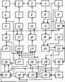
На чертеже представлена структурная схема устройства стабилизации тока пучка заряженных частиц. The drawing shows a structural diagram of a device for stabilizing the current of a beam of charged particles.
Устройство содержит источник 1 электронов, управляемых импульсным модулятором 6, связанным с системой 11 синхронизации ускорителя, N ускоряющих секций 2,3, соединенных последовательно и подключенных к выходу источника 1 электронов, N импульсных усилителей ВЧ 7,8, подключенных к входам ввода СВЧ-мощности соответствующих им ускоряющих секций и управляемых соответствующими им модуляторами 12, 13, магнитоиндукционный датчик 4, соединенный через измеритель 9 заряда пучка с аналого-цифровым преобразователем (АЦП) 14, выход которого подключен к информационному входу сумматора 19, выходом связанным с первым входом цифровой схемы 24 сравнения, а входом разрешения выхода соединенным с выходом второй линии 10 задержки, вход которой соединен с выходом таймера 15, также подключенного к входу установки таймера в ноль, и с первыми входами первого и второго элементов И 25,30, а вход таймера связан с выходом системы 11 синхронизации ускорителя, который также подключен к входам N управляемых линий 17,18 задержки, соединенных с соответствующими им модуляторами ВЧ-усилителей 12,13, к входу делителя 16 и через первую линию 5 задержки подключен к входу разрешения преобразования АЦП 14. Второй вход цифровой схемы 24 сравнения соединен с устройством 20 предустановки величины тока пучка, а выход "Меньше" подключен к второму входу первого элемента И 25, выход которого соединен с входом установки в логическую "1" первого триггера 29, со счетным входом первого счетчика 34, с входом установки в ноль третьего счетчика 32 и с входом первого формирователя 35 сигналов, выход которого подключен к входу разрешения записи второго счетчика 33, информационный вход которого соединен с выходом первого счетчика 34, а вход обратного счета соединен с входом обратного счета четвертого счетчика 31 и через третью линию 21 задержки соединен с выходом делителя 16, который подключен к первым входам N элементов ИЛИ 22, 23, выходы которых соединены с входами управления соответствующих им управляемых линий 17,18 задержки, вторые входы N элементов ИЛИ 22,23 подключены к выходу третьего элемента И 27, а третьи их входы соединены с выходом первого триггера 29, который также подключен к входу разрешения счета второго счетчика 33, выход переноса которого соединен с входом сброса первого триггера 29. Выход "Больше" цифровой схемы 24 сравнения подключен к второму входу второго элемента И 30, выход которого соединен с входом установки в логическую "1" второго триггера 26, со счетным входом третьего счетчика 32, с входом установки в ноль первого счетчика 34 и с входом второго формирователя 28 сигналов, выход которого подключен к входу разрешения записи четвертого счетчика 31, информационный вход которого соединен с выходом третьего счетчика 32, а выход переноса подключен к входу сброса второго триггера 26, выход которого соединен с входом разрешения счета четвертого счетчика 31 и с вторым входом третьего элемента И 27. The device comprises an
В качестве цифровой схемы 24 сравнения в устройстве могут быть использованы цифровые компараторы, выполненные на микросхемах типа 564ИП2, К555СП1. Конструкция и принцип действия магнитоиндукционного датчика 4 описаны в работе: Москалев В. А. , Сергеев Г. И. , Шестаков В. Г. Измерение параметров пучков заряженных частиц. М. : Атомиздат, 1980. Измеритель 9 заряда описан в работе: Ушаков В. И. , Стервоедов Н. Г. , Боржковский В. Ф. Измеритель заряда в импульсе ускоренного пучка электронов. Приборы и техника эксперимента, 1986, N 5, с. 25-27. Управляемые линии 17,18 задержки построены на основе принципов, описанных в работе: Важенина З. П. , Волкова Н. И. , Чадович И. И. Методы и схемы временной задержки импульсных сигналов. М. : Советское радио, 1971, с. 284. Таймер представляет собой счетчик импульсов синхронизации. В качестве делителя применен делитель на 2, выполненный на базе двоичного счетчика. Средний ток пучка определяется как отношение суммарного заряда импульсов пучка на выбранном интервале усреднения к величине этого интервала. При постоянном интервале усреднения можно считать, что средний ток пучка пропорционален суммарному заряду импульсов пучка на этом интервале. As a
Импульсы пучка и импульсы СВЧ-мощности, подающиеся в ускоряющие секции ускорителя, заранее синхронизированы так, чтобы получить оптимальный энергетический спектр пучка на выходе ускорителя. Величина суммарного заряда импульсов пучка регулируется тем, что часть импульсов синхронизации запускает усилители СВЧ, подающие СВЧ-мощности в ускоряющие секции, не синхронно с импульсами пучка. Регулируя количество таких импульсов, можно регулировать суммарный заряд пучка, а значит, средний ток пучка. При этом энергетический спектр пучка не искажается. Если на интервале усреднения половина импульсов синхронизации запускает усилители СВЧ синхронно с импульсами пучка, а вторая половина - нет, то есть возможность регулировать суммарный заряд импульсов пучка от "0" до наибольшего его значения. При этом для создания равномерного режима работы ускорителя синхронизованные и несинхронизованные импульсы чередуются. Рассогласование импульсов СВЧ-мощности и импульсов пучка достигается увеличением задержки импульсов синхронизации, запускающих модуляторы усилителей СВЧ при помощи управляемых линий задержки, за рабочие пределы. The pulses of the beam and pulses of microwave power supplied to the accelerating sections of the accelerator are synchronized in advance so as to obtain the optimal energy spectrum of the beam at the output of the accelerator. The magnitude of the total charge of the beam pulses is regulated by the fact that part of the synchronization pulses triggers microwave amplifiers, which supply microwave power to the accelerating sections, not synchronously with the beam pulses. By adjusting the number of such pulses, it is possible to adjust the total charge of the beam, and hence the average beam current. In this case, the energy spectrum of the beam is not distorted. If in the averaging interval, half of the synchronization pulses starts microwave amplifiers synchronously with the beam pulses, and the second half does not, then it is possible to adjust the total charge of the beam pulses from "0" to its highest value. In this case, to create a uniform mode of operation of the accelerator, synchronized and unsynchronized pulses alternate. The mismatch of microwave power pulses and beam pulses is achieved by increasing the delay of the synchronization pulses, triggering the modulators of microwave amplifiers using controlled delay lines, beyond the operating limits.
Рассмотрим подробнее процесс стабилизации среднего тока пучка. В течение всего интервала усреднения суммируются заряды импульсов пучка и в конце этого интервала суммарный заряд, пропорциональный по величине среднему току пучка на этом интервале, сравнивается с заданной величиной. Если при сравнении оказывается, что суммарный заряд меньше заданной величины, то количество синхроимпульсов, запускающих усилитель СВЧ несинхронно с импульсами пучка на следующем интервале усреднения, уменьшается на один. В конце следующего интервала усреднения происходит очередное сравнение суммарного заряда импульсов пучка с заданной величиной, и если результат сравнения оказывается прежним, то количество синхроимпульсов, запускающих усилители СВЧ несинхронно с импульсами пучка, уменьшится на следующем интервале усреднения еще на один, то есть составит на этом интервале усреднения уже два. Таким образом, количество синхроимпульсов, запускающих усилители СВЧ несинхронно с импульсами пучка, будет уменьшаться на каждом последующем интервале усреднения на один до тех пор, пока результат сравнения суммарного заряда импульсов пучка и заданной величины не изменится. В этом случае суммарный заряд становится больше чем надо и количество синхроимпульсов, запускающих усилители СВЧ несинхронно с импульсами пучка на каждом интервале усреднения, будет последовательно увеличиваться на один до изменения результатов сравнения и процесс пойдет в обратном порядке. Let us consider in more detail the process of stabilization of the average beam current. During the entire averaging interval, the beam impulse charges are summed up and at the end of this interval, the total charge, which is proportional to the average beam current in this interval, is compared with a predetermined value. If during the comparison it turns out that the total charge is less than the specified value, then the number of clock pulses starting the microwave amplifier asynchronously with the beam pulses in the next averaging interval decreases by one. At the end of the next averaging interval, the next comparison of the total charge of the beam pulses with a given value takes place, and if the comparison result is the same, the number of clock pulses starting the microwave amplifiers asynchronously with the beam pulses will decrease by one more in the next averaging interval, i.e., in this interval there are already two averagings. Thus, the number of clock pulses starting the microwave amplifiers asynchronously with the pulses of the beam will decrease in each subsequent averaging interval by one until the result of comparing the total charge of the pulses of the beam and the given value changes. In this case, the total charge becomes larger than necessary and the number of clock pulses starting the microwave amplifiers asynchronously with the beam pulses in each averaging interval will sequentially increase by one until the comparison results change and the process goes in the reverse order.
Изменяя интервал усреднения, можно менять постоянную времени отработки предлагаемого устройства, но при этом также меняется точность отработки, так как она определяется вкладом каждого импульса пучка. Чем меньше интервал усреднения, тем больше вклад каждого импульса пучка и тем грубее будет отработка изменений среднего тока. Ввиду этих соображений выбирается оптимальный интервал усреднения в зависимости от условий проведения физического эксперимента. Рассмотрим подробнее работу предлагаемого устройства по его структуpной схеме. Changing the averaging interval, you can change the time constant of the proposed device, but the accuracy of the change also changes, since it is determined by the contribution of each beam pulse. The smaller the averaging interval, the greater the contribution of each beam pulse and the coarser the development of changes in the average current will be. In view of these considerations, the optimal averaging interval is selected depending on the conditions of the physical experiment. Let us consider in more detail the operation of the proposed device according to its structural scheme.
Источник 1 электронов, управляемый импульсным модулятором 6 источника, запускаемый системой 11 синхронизации ускорителя, вырабатывает импульсные посылки электронов, которые поступают в последовательно соединенные ускоряющие секций 2, 3. На входы для ввода СВЧ-мощности каждой из них поступает мощность от соответствующего каждой ускоряющей секции импульсного ВЧ-усилителя 7.8. Импульсные ВЧ-усилители 7,8 управляются модуляторами 12,13. Запуск модуляторов 12, 13 осуществляется синхроимпульсами, задержанными управляемыми линиями 17,18 задержки на заранее выбранную оптимальную с точки зрения конфигурации энергетического спектра пуска величину, но при этом каждый второй синхроимпульс, снимаемый с выхода делителя 16 на два, через элементы ИЛИ 22,23 поступает на входы управления управляемых линий 17,18 задержки, воздействуя на них так, что задержка, создаваемая управляемыми линиями задержки 17,18, возрастает на величину, превышающую рабочую, тем самым создавая рассогласование между импульсами пучка и импульсами запуска усилителей СВЧ. Таким образом осуществляется чередование синхронного с импульсами пучка запуска усилителей СВЧ и несинхронного, то есть средний ток пучка определяется только половиной импульсов пучка. Сигнал с выхода магнитоиндукционного датчика 4 через измеритель 9 заряда пучка поступает на АЦП 14, на вход разрешения преобразования которого поступают синхроимпульсы, задержанные первой линией 5 задержки на время, необходимое для срабатывания магнитоиндукционного датчика 4 и измерителя 9 заряда пучка. Значение величины заряда каждого импульса пучка суммируется сумматором 19. Интервал измерения задается таймером 15, являющимся двоичным счетчиком, считающим синхроимпульсы. При поступлении заданного количества синхроимпульсов, определяющих интервал усреднения, таймер 15 вырабатывает импульс окончания интервала, который зануляет таймер 15 и через вторую линию 10 задержки поступает на вход разрешения выхода сумматора 19. При поступлении этого импульса на выходе сумматора 19 устанавливается величина суммарного заряда импульсов пучка за интервал измерения. Задержка, создаваемая второй линией 10 задержки, определяется временем, необходимым для срабатывания устройств 4,9,14,19. Выходной код сумматора 19 поступает на первый вход схемы 24 сравнения, на второй вход которой подается код с устройства 20 предустановки величины тока пучка. The
Предположим, что в результате сравнения величины заряда импульсов пучка и заданной величины в конце очередного интервала усреднения на выходе "Меньше" схемы 24 сравнения установилась логическая "1", а на выходе "Больше" - логический "0", то есть суммарный заряд пучка за интервал усреднения меньше, чем задается устройством 20 предустановки. Импульс окончания интервала с выхода таймера 15 через первый элемент И 25 поступает на счетный вход первого счетчика 34, устанавливая на его выходе код, равный единице, и через первый формирователь 35 поступает на вход разрешения записи второго счетчика 33, по которому в него записывается информация с первого счетчика 34, в данном случае равная единице. Кроме того, этот сигнал поступает на вход установки в единицу первого триггера 29, выходной сигнал которого блокирует элементы ИЛИ 22,23 и, поступая на вход разрешения счета второго счетчика 33, разрешает счет. При этом первый синхроимпульс нового интервала усреднения поступает на входы управляемых линий 17,18 задержки и после задержки на заданную, оптимальную с точки зрения конфигурации энергетического спектра пучка, величину запускает модуляторы 12,13 усилителей СВЧ 7,8 синхронно с импульсом пучка. По второму синхроимпульсу делитель 16 вырабатывает импульс, поступающий на заблокированные первым триггером 29 элементы ИЛИ 22,23 и не воздействует на входы управления управляемых линий 17,18 задержки. Поэтому второй синхроимпульс задерживается управляемыми линиями 17,18 задержки так же на оптимальную величину и запускает модуляторы 12,13 усилителей СВЧ 7,8 синхронно с импульсом пучка. Задержанный третьей линией 21 задержки на время прохождения второго синхроимпульса импульс делителя 16 поступает на вход обратного счета второго счетчика 33 и, вычитая единицу, зануляет его. Сигнал с выхода переноса второго счетчика 33 сбрасывает первый триггер 29, выходной сигнал которого разблокирует элементы ИЛИ 22,23 и, поступая на вход разрешения счета второго счетчика 33, блокирует его. Suppose that as a result of comparing the magnitude of the charge of the pulses of the beam and the given value at the end of the next averaging interval, the logical “1” is established at the output of the “Less”
В дальнейшем каждый четный синхроимпульс этого интервала усреднения через элементы ИЛИ 22,23 поступает на входы управляемых линий 17,18 задержек, которые смещают их за рабочие пределы и нарушают синхронизацию между импульсами ускорителя и импульсами СВЧ-мощности. Subsequently, each even sync pulse of this averaging interval through the OR
Таким образом на данном интервале усреднения количество синхроимпульсов, запускающих усилители СВЧ несинхронно с импульсами пучка, уменьшилось на один. Это должно привести к возрастанию суммарного заряда импульсов пучка на величину, определяемую зарядом одного импульса пучка. Если результат сравнения суммарного заряда импульсов пучка с заданной величиной, произведенный в конце этого интервала усреднения, остался прежним, то импульс таймера 15, появляющийся в конце этого интервала, опять через первый элемент И 25 поступает на счетный вход первого счетчика 34 и устанавливает на его выходе код, равный теперь уже двум, и через первый формирователь 35 поступает на вход разрешения записи второго счетчика 33, по которому в него записывается информация с первого счетчика 34, в данном случае равная 2. Кроме того, этот сигнал поступает на вход установки 1 первого триггера 29, выходной сигнал которого блокирует элементы ИЛИ 22,23 и поступает на вход разрешения счета второго счетчика 33. При этом первые четыре синхроимпульса нового интервала усреднения поступают через управляющие линии 17,18 задержки и запускают модуляторы усилителей СВЧ 7,8 в соответствии с заранее выставленной задержкой синхронно с импульсами пучка. По второму и четвертому синхроимпульсам делитель 16 вырабатывает импульсы, поступающие на заблокированные первым триггером 29 элементы ИЛИ 22,23 и не воздействующие на входы управления управляемых линий 17, 18 задержки. Задержанные третьей линией 21 задержки два импульса делителя 16 поступают на вход обратного счета второго счетчика 33 и зануляют его. Сигнал с выхода переноса второго счетчика 33 сбрасывает первый триггер 29, выходной сигнал которого разблокирует элементы ИЛИ 17,18 и, поступая на вход разрешения счета второго счетчика 33, блокирует его. Thus, in this averaging interval, the number of clock pulses starting the microwave amplifiers asynchronously with the beam pulses decreased by one. This should lead to an increase in the total charge of the beam pulses by an amount determined by the charge of one beam pulse. If the result of comparing the total charge of the beam pulses with a given value, produced at the end of this averaging interval, remains the same, then the
В дальнейшем устройство работает как и в первом случае. Таким образом на данном интервале усреднения количество синхроимпульсов, запускающих усилители СВЧ 7,8 несинхронно с импульсами пучка, уменьшилось теперь на два. Это должно привести к возрастанию суммарного заряда импульсов пучка на величину, определяемую зарядами двух импульсов пучка. Если результат сравнения, произведенный в конце этого интервала усреднения, остается прежним, то устройство уменьшит на следующем интервале усреднения количество синхроимпульсов, запускающих усилители СВЧ несинхронно с импульсами пучка, до трех и т. д. до тех пор, пока результат сравнения не станет противоположным. В этом случае на выходе "Меньше" схемы 24 сравнения появится логический "0", а на выходе "Больше" - логическая "1". При этом первый элемент И 25 блокируется. Импульс таймера 15, появляющийся в конце интервале усреднения, через второй элемент И 30 поступает на вход установки в ноль первого счетчика 34, сбрасывая его, поступает на счетный вход третьего счетчика 32, устанавливая на его выходе код, равный 1, поступает через второй формирователь 28 на вход разрешения записи четвертого счетчика 31, по которому в него записывается информация с третьего счетчика 32 и в данном случае равная 1, поступает на вход установки в "1" второго триггера 26, выходной сигнал которого поступает на вход разрешения счета четвертого счетчика 31 и на вход третьего элемента И 27, разрешая прохождение через него синхроимпульсов. Первый синхроимпульс нового интервала усреднения поступает через третий элемент И 27 и элементы ИЛИ 22, 23 на управляющие входы управляемых линий 17, 18 задержки, которые смещают его задержки за рабочие пределы, при этом происходит рассогласование импульса пучка с импульсами СВЧ-мощности, поступающими в ускоряющие секции 2,3. По второму синхроимпульсу импульс делителя 16 совместно с вторым синхроимпульсом опять поступает через элементы ИЛИ 22,23 на входы управления управляемых линий 17,18 задержки, смещая задержку за рабочие пределы. Кроме того, импульс делителя 16, задержанный третьей линией 21 задержки на время прохождения второго синхроимпульса, поступает на вход обратного счета четвертого счетчика 31 и зануляет его. Сигнал с выхода переноса четвертого счетчика 21 сбрасывает второй триггер 26, выходной сигнал которого блокирует третий элемент И 27 и, поступая на вход разрешения счета четвертого счетчика 31, блокирует его. В дальнейшем устройство работает в обычном режиме. In the future, the device operates as in the first case. Thus, in this averaging interval, the number of clock pulses starting the microwave amplifiers 7.8 asynchronously with the beam pulses has now decreased by two. This should lead to an increase in the total charge of the beam pulses by an amount determined by the charges of two beam pulses. If the comparison result produced at the end of this averaging interval remains the same, then the device will reduce the number of clock pulses starting the microwave amplifiers asynchronously with the beam pulses in the next averaging interval to three, etc., until the comparison result becomes the opposite. In this case, the output “Less” of the
Таким образом, на данном интервале усреднения количество синхроимпульсов, запускающих усилители СВЧ несинхронно с импульсами пучка, увеличилось на один. Это должно привести к уменьшению суммарного заряда импульсов пучка на величину, определяемую зарядом одного импульса пучка. Если результат сравнения суммарного заряда импульсов пучка с заданной величиной, произведенный в конце интервала усреднения, остался прежним, устройство на следующем интервале усреднения увеличит количество синхроимпульсов, запускающих усилители СВЧ несинхронно с импульсами пучка, до 2-х и т. д. до тех пор, пока результат сравнения не изменится. На выходах схемы 24 сравнения сигналы изменят полярность, импульс с выхода первого элемента И 25 устанавливает третий счетчик 32 в нуль, а устройство отрабатывает сигнал рассогласования. Таким образом осуществляется регулирование среднего тока пучка заряженных частиц в линейном ускорителе. Thus, in this averaging interval, the number of clock pulses triggering microwave amplifiers asynchronously with the beam pulses increased by one. This should lead to a decrease in the total charge of the beam pulses by an amount determined by the charge of one beam pulse. If the result of comparing the total charge of the beam pulses with a given value, made at the end of the averaging interval, remains the same, the device in the next averaging interval will increase the number of clock pulses starting the microwave amplifiers asynchronously with the beam pulses, up to 2, etc., until until the result of the comparison changes. At the outputs of the
Введение существенных отличий позволяет убрать искажения энергетического спектра пучка заряженных частиц в процессе стабилизации его среднего тока. Это следует из того, что для стабилизации среднего тока пучка не применяется регулирование тока эмиссии электронов и регулирование синхронизации импульсов пучка и импульсов СВЧ-мощности, поступающих в ускоряющие секции ускорителя, как это принято на практике. Указанные регулировки являются причиной искажения энергетического спектра пучка на выходе ускорителя, что показано в работах: Лебедев А. Н. , Шальнов А. В. Основы физики и техники ускорителей. М. : Энергоатомиздат, 1983. Т. 3, с. 80,82,83,87,105; Улучшение энергетического спектра в ускорителях со стоячей волной задержкой инжекции/ В. Ф. Викулов, В. Н. Заворотный, В. В. Рузин, В. К. Шилов// ЖТФ, 1982, т. 52, вып. 11, с. 2188-2191. Таким образом, предлагаемое устройство, использующее иной принцип регулирования среднего тока пучка, лишено указанных недостатков, что позволяет сохранить спектр пучка неискаженным в процессе стабилизации, а значит, улучшить условия проведения физических экспериментов и, как следствие, сократить затраты на их проведение. The introduction of significant differences makes it possible to remove distortions in the energy spectrum of a charged particle beam in the process of stabilization of its average current. This follows from the fact that, to stabilize the average beam current, the electron emission current is not applied and the synchronization of the beam pulses and microwave power pulses arriving at the accelerating sections of the accelerator is not used, as is usual in practice. These adjustments are the cause of the distortion of the energy spectrum of the beam at the output of the accelerator, as shown in the works: A. Lebedev, A. Shalnov. Fundamentals of physics and technology of accelerators. M.: Energoatomizdat, 1983. T. 3, p. 80.82.83.87.105; Improving the energy spectrum in accelerators with a standing wave delayed injection / V.F. Vikulov, V.N. Zavorotny, V.V. Ruzin, V.K. Shilov // ZhTF, 1982, v. 52, no. 11, p. 2188-2191. Thus, the proposed device, using a different principle of regulating the average beam current, is devoid of these drawbacks, which allows the beam spectrum to be undistorted in the stabilization process, which means that the conditions for conducting physical experiments are improved and, as a result, the costs of conducting them are reduced.
Claims (1)
Priority Applications (1)
| Application Number | Priority Date | Filing Date | Title |
|---|---|---|---|
| SU4846311 RU2012167C1 (en) | 1990-07-03 | 1990-07-03 | Charge-particle beam current regulator |
Applications Claiming Priority (1)
| Application Number | Priority Date | Filing Date | Title |
|---|---|---|---|
| SU4846311 RU2012167C1 (en) | 1990-07-03 | 1990-07-03 | Charge-particle beam current regulator |
Publications (1)
| Publication Number | Publication Date |
|---|---|
| RU2012167C1 true RU2012167C1 (en) | 1994-04-30 |
Family
ID=21524836
Family Applications (1)
| Application Number | Title | Priority Date | Filing Date |
|---|---|---|---|
| SU4846311 RU2012167C1 (en) | 1990-07-03 | 1990-07-03 | Charge-particle beam current regulator |
Country Status (1)
| Country | Link |
|---|---|
| RU (1) | RU2012167C1 (en) |
Cited By (1)
| Publication number | Priority date | Publication date | Assignee | Title |
|---|---|---|---|---|
| CN116699675A (en) * | 2023-06-26 | 2023-09-05 | 国电投核力电科(无锡)技术有限公司 | Quick calibration and calculation method and quick calibration system for improving beam position measurement precision |
-
1990
- 1990-07-03 RU SU4846311 patent/RU2012167C1/en active
Cited By (2)
| Publication number | Priority date | Publication date | Assignee | Title |
|---|---|---|---|---|
| CN116699675A (en) * | 2023-06-26 | 2023-09-05 | 国电投核力电科(无锡)技术有限公司 | Quick calibration and calculation method and quick calibration system for improving beam position measurement precision |
| CN116699675B (en) * | 2023-06-26 | 2025-06-13 | 国电投核力电科(无锡)技术有限公司 | A fast calibration and calculation method for improving beam position measurement accuracy and a fast calibration system |
Similar Documents
| Publication | Publication Date | Title |
|---|---|---|
| Zhao et al. | Femtosecond relativistic electron beam with reduced timing jitter from THz driven beam compression | |
| US4024426A (en) | Standing-wave linear accelerator | |
| US11165427B2 (en) | Configurable linear accelerator frequency control system and method | |
| US3914623A (en) | Waveform generator including means for automatic slope calibration | |
| RU2012167C1 (en) | Charge-particle beam current regulator | |
| US3710163A (en) | Method for the acceleration of ions in linear accelerators and a linear accelerator for the realization of this method | |
| Wang et al. | Determination of the geometry factor for longitudinal perturbations in space-charge dominated beams | |
| Chen et al. | Commissioning the photoinjector of a gamma-ray light source | |
| US4000440A (en) | Method and apparatus for controlling brightness and alignment of a beam of charged particles | |
| Tanaka et al. | Low émittance injector at SCSS | |
| GB2143350A (en) | Producing control signals in timed relation to an a.c. waveform | |
| Norris et al. | Velocity Modulation System for Enhancement of 50 Picosecond Radiation Pulse | |
| Xie et al. | First lasing of the Beijing FEL | |
| SU1101167A1 (en) | Method of controlling outlet of cyclotron beam and device for effecting same | |
| SU1478983A1 (en) | Method of stabilizing energy of electrons | |
| Hodgson et al. | A trigger generator to control a linear accelerator for pulse radiolysis | |
| Smith et al. | RF system upgrades to the advanced photon source linear accelerator in support of the FEL operation | |
| Mondelaers et al. | Optimisation of the output performance of a high intensity linear electron accelerator | |
| Hanaki et al. | Beam stabilization in the SPring-8 linac | |
| Boriskin et al. | Monitoring of the electron beam position in industrial linacs | |
| Boni et al. | DAΦNE Linac operational performance | |
| Fenger | A single-pulse trigger generator for a 10 MeV electron linear accelerator | |
| Zaleskyi et al. | MODERNIZATION AND ADJUSTMENT OF THE MICROWAVE POWER CONTROL SYSTEM OF THE “ALMAZ-2M” ACCELERATOR | |
| Kuriki et al. | Energy stabilization of 1.5 GeV S-Band linac | |
| Fischer | Improvement of the CPS flat top operation by regulating the mean speed of the alternator set |