RU2012139C1 - Device for service communication - Google Patents

Device for service communication Download PDF

Info

Publication number
RU2012139C1
RU2012139C1 SU4878608A RU2012139C1 RU 2012139 C1 RU2012139 C1 RU 2012139C1 SU 4878608 A SU4878608 A SU 4878608A RU 2012139 C1 RU2012139 C1 RU 2012139C1
Authority
RU
Russia
Prior art keywords
input
output
inputs
unit
outputs
Prior art date
Application number
Other languages
Russian (ru)
Inventor
А.С. Родин
А.П. Шабанов
Original Assignee
Войсковая Часть 25871
Priority date (The priority date is an assumption and is not a legal conclusion. Google has not performed a legal analysis and makes no representation as to the accuracy of the date listed.)
Filing date
Publication date
Application filed by Войсковая Часть 25871 filed Critical Войсковая Часть 25871
Priority to SU4878608 priority Critical patent/RU2012139C1/en
Application granted granted Critical
Publication of RU2012139C1 publication Critical patent/RU2012139C1/en

Links

Images

Landscapes

  • Use Of Switch Circuits For Exchanges And Methods Of Control Of Multiplex Exchanges (AREA)

Abstract

FIELD: electrical communication. SUBSTANCE: device has conversation unit, coder-decoder, switching unit, command receivers, command distribution unit, clock input and command recording input. The command receiver has the first counter, flip-flop, OR gate, decoders unit, series-parallel register, AND gates and delay line. The conversation unit has amplifier, handset, decoder, flip-flops, indication and warning assembly, series-parallel register and dialing assembly. Switching unit has register, comparator, OR gates, parallel-series register, counter, flip-flop, AND gate. Command distribution unit has interrupt priority former, control circuit, group of registers, group of OR gates and decoder. EFFECT: reduced time for connecting calling and called parties by avoiding conflict situations. 4 dwg

Description

Изобретение относится к электросвязи и может быть использовано для организации служебной связи по цифровым каналам. The invention relates to telecommunications and can be used to organize service communications on digital channels.

Цель изобретения - сокращение времени установления соединения между абонентами путем устранения конфликтных ситуаций. The purpose of the invention is to reduce the time to establish a connection between subscribers by eliminating conflict situations.

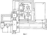
На фиг. 1 представлена структурная схема устройства служебной связи с отображением структурной электрической схемы приемника команд. На фиг. 2-4 - структурные схемы переговорного блока, блока коммутации и блока распределения команд, соответственно. In FIG. 1 is a structural diagram of an intercom device with a structural block diagram of a command receiver. In FIG. 2-4 are structural diagrams of a conversation unit, a switching unit, and a command distribution unit, respectively.

Устройство служебной связи (см. фиг. 1) содержит приемники 11. . . 1n команд, переговорный блок 2, блок коммутации 3, кодер-декодер 4, блок 5 распределения команд. Первый вход переговорного блока 2 подключен к третьему выходу блока коммутации 3, первый выход которого соединен с первым входом кодера-декодера 4, первый выход которого соединен с первым входом блока коммутации 3, вторые входы которого соединены с первыми входами соответствующих приемников 11. . . 1n команд и являются канальными входами устройства, выходами которого являются вторые выходы коммутации блока 3. Первый и второй выходы блока распределения 5 команд соединены соответственно с третьим и четвертым входами блока коммутации 3, пятый вход которого подключен к вторым входам приемников 11. . . 1n команд, к пятому входу блока распределения 5 команд, к третьему входу кодера-декодера 4 и к третьему входу переговорного блока 2, второй выход которого соединен с вторым входом кодера-декодера 4, второй выход которого соединен с вторым входом переговорного блока 2, первый, третий и четвертый выходы которого соединены, соответственно с вторым, первым и третьим входами блока 5 распределения команд, четвертые, седьмые и шестые входы которого подключены, соответственно, к третьему, второму и первому выходам приемников 11. . . 1n команд, а пятый и шестой входы блока коммутации 3 являются соответственно тактовым входом 6 и входом 7 записи команд устройства.The intercom device (see Fig. 1) contains receivers 1 1 . . . 1 n commands, communication unit 2, switching unit 3, encoder-decoder 4, block 5 distribution of commands. The first input of the talking unit 2 is connected to the third output of the switching unit 3, the first output of which is connected to the first input of the encoder-decoder 4, the first output of which is connected to the first input of the switching unit 3, the second inputs of which are connected to the first inputs of the respective receivers 1 1 . . . 1 n commands and are the channel inputs of the device, the outputs of which are the second outputs of the switching unit 3. The first and second outputs of the distribution unit 5 teams are connected respectively to the third and fourth inputs of the switching unit 3, the fifth input of which is connected to the second inputs of the receivers 1 1 . . . 1 n commands, to the fifth input of the distribution block of 5 commands, to the third input of the encoder-decoder 4 and to the third input of the intercom unit 2, the second output of which is connected to the second input of the encoder-decoder 4, the second output of which is connected to the second input of the intercom unit 2, the first, third and fourth outputs of which are connected, respectively, with the second, first and third inputs of the command distribution unit 5, the fourth, seventh and sixth inputs of which are connected, respectively, to the third, second and first outputs of the receivers 1 1 . . . 1 n commands, and the fifth and sixth inputs of the switching unit 3 are clock input 6 and input 7 of the device command record, respectively.

Приемник команд 1 содержит счетчик 8, триггер 9, элемент ИЛИ 10, блок 11 дешифраторов, последовательно-параллельный регистр 12, элементы И 13 и 14 и линию задержки 15. Выход линии задержки 15 соединен с вторым входом первого элемента И 13, первый вход которого подключен к первому входу второго элемента И 14 и к выходу триггера 9, первый вход которого соединен с первым входом счетчика 8 и с выходом элемента ИЛИ 10. Входы элемента ИЛИ 10 подключены к выходам блока 11 дешифраторов, входы которого подключены к выходам последовательно-параллельного регистра 12, первый вход которого соединен со вторым входом второго элемента И 14 и с вторым входом счетчика 8, третий вход которого подключен к второму входу триггера 9 и к выходу счетчика 8. Второй вход последовательно-параллельного регистра 12 соединен с входом линии задержки 15 и является первым входом приемника 1, вторым входом которого является второй вход второго элемента И 14, выход которого является третьим выходом приемника, первым и вторым выходами которого являются соответственно выход триггера 9 и выход первого элемента И 13. The receiver 1 contains a counter 8, a trigger 9, an OR element 10, a decoder block 11, a parallel-parallel register 12, the elements 13 and 14 and a delay line 15. The output of the delay line 15 is connected to the second input of the first element And 13, the first input of which connected to the first input of the second element And 14 and to the output of the trigger 9, the first input of which is connected to the first input of the counter 8 and the output of the element OR 10. The inputs of the element OR 10 are connected to the outputs of the block 11 of the decoders, the inputs of which are connected to the outputs of the serial-parallel register 12, ne the output of which is connected to the second input of the second element And 14 and to the second input of the counter 8, the third input of which is connected to the second input of the trigger 9 and to the output of the counter 8. The second input of the serial-parallel register 12 is connected to the input of the delay line 15 and is the first input the receiver 1, the second input of which is the second input of the second element And 14, the output of which is the third output of the receiver, the first and second outputs of which are respectively the output of the trigger 9 and the output of the first element And 13.

Переговорный блок 2 (см. фиг. 2) содержит усилитель 16, микротелефонную трубку 17, два триггера 18 и 19, узел сигнализации 20, параллельно-последовательный регистр 21, узел 22 набора номера и дешифратор 23. Выходы дешифратора 23 подключены к вторым входам первого 18 и второго 19 триггеров, выходы которых соединены соответственно с первым и вторым входами узла сигнализации 20, первый вход второго триггера 19 подключен к третьему выходу узла 22 набора номера, вторые выходы которого соединены с соответствующими вторыми входами параллельно-последовательного регистра 21. Второй выход усилителя 16 соединен с входом микротелефонной трубки 17, выход которой соединен с вторым входом усилителя 16, первый выход которого является вторым выходом переговорного блока 2, первым, третьим и четвертым выходами которого являются соответственно первый выход узла 22 набора номера, выход параллельно-последовательного регистра 21 и третий выход узла 22 набора номера, первый вход параллельно-последовательного регистра 21 является третьим входом переговорного блока 2, первым и вторым входами которого являются соответственно вход дешифратора 23 и первый вход усилителя 16. The conversation unit 2 (see Fig. 2) contains an amplifier 16, a handset 17, two triggers 18 and 19, an alarm unit 20, a parallel-serial register 21, a dialing unit 22 and a decoder 23. The outputs of the decoder 23 are connected to the second inputs of the first 18 and second 19 triggers, the outputs of which are connected respectively to the first and second inputs of the signaling unit 20, the first input of the second trigger 19 is connected to the third output of the dialing unit 22, the second outputs of which are connected to the corresponding second inputs of the parallel-serial p register 21. The second output of the amplifier 16 is connected to the input of the handset 17, the output of which is connected to the second input of the amplifier 16, the first output of which is the second output of the intercom unit 2, the first, third and fourth outputs of which are the first output of the dialing unit 22, the output parallel-serial register 21 and the third output of the dialing unit 22, the first input of the parallel-serial register 21 is the third input of the conversation unit 2, the first and second inputs of which are respectively enno decoder input 23 and a first input of the amplifier 16.

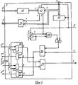
Блок 3 коммутации (см. фиг. 3) содержит группу 24 элементов И, группу 25 элементов ИЛИ, элементы ИЛИ 26 и 27, элемент И 28, триггер 29, счетчик 30, параллельно-последовательный регистр 31, узел сравнения 32 и регистр 33. Выход регистра 33 соединен с первым входом узла 32 сравнения, второй вход которого подключен к первому входу параллельно-последовательного регистра 31 и к второму входу группы 25 элементов ИЛИ, первый вход которой подключен к первому выходу узла сравнения 32, второй выход которого соединен с первым входом счетчика 30 и с первым входом триггера 29, второй вход которого подключен к выходу счетчика 30 и к второму входу счетчика 30, третий вход которого соединен с третьим входом узла 32 сравнения и с вторым входом параллельно-последовательного регистра 31, выход которого соединен с первым входом элемента И 28, второй вход которого подключен к выходу триггера 29. Выход элемента И 28 соединен с первым входом первого элемента ИЛИ 26, выход которого соединен с третьими входами группы 24 элементов И, вторые входы которой соединены с входами второго элемента ИЛИ 27, выход которого является первым выходом блока коммутации 3, вторыми и третьими выходами которого являются соответственно первые выходы группы 24 элементов И и выход группы 25 элементов ИЛИ, второй вход которой является третьим входом блока коммутации 3, первым, вторым, четвертым, пятым и шестым входами которого являются соответственно второй вход первого элемента ИЛИ 26, первые входы группы 24 элементов И, вторые входы группы 24 элементов И, третий вход счетчика 30 и вход регистра 33. The switching unit 3 (see Fig. 3) contains a group of 24 AND elements, a group of 25 OR elements, OR elements 26 and 27, an AND element 28, a trigger 29, a counter 30, a parallel-serial register 31, a comparison node 32, and a register 33. The output of the register 33 is connected to the first input of the comparison unit 32, the second input of which is connected to the first input of the parallel-serial register 31 and to the second input of the OR group 25, the first input of which is connected to the first output of the comparison unit 32, the second output of which is connected to the first input counter 30 and with the first input of trigger 29, the second input of which is connected to the output of the counter 30 and to the second input of the counter 30, the third input of which is connected to the third input of the comparison unit 32 and to the second input of the parallel-serial register 31, the output of which is connected to the first input of the AND element 28, the second input of which is connected to the trigger output 29. The output of the AND element 28 is connected to the first input of the first OR element 26, the output of which is connected to the third inputs of the group of 24 AND elements, the second inputs of which are connected to the inputs of the second OR element 27, the output of which is the first output switching unit 3, the second and third outputs of which are respectively the first outputs of the group of 24 AND elements and the output of the group of 25 OR elements, the second input of which is the third input of switching unit 3, the first, second, fourth, fifth and sixth inputs of which are the second input of the first OR element 26, the first inputs of the group of 24 AND elements, the second inputs of the group of 24 AND elements, the third input of the counter 30 and the input of the register 33.

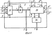
Блок 5 распределения команд (см. фиг. 4) содержит группу 34 элементов ИЛИ, группу 35 регистров, дешифратор 36 и формирователь 37 сигнала приоритетного прерывания, выход которого соединен с первым входом дешифратора 36, выход которого соединен с третьим входом группы 35 регистров, выходы которой подключены к входам группы 34 элементов ИЛИ. Второй вход дешифратора 36 подключен к второму входу формирователя 37 сигнала приоритетного прерывания, третий вход которого соединен с четвертым входом группы 35 регистров, первый, вторые и пятые входы которой являются соответственно первым, четвертым и шестыми входами блока 5 распределения команд, вторым, третьим, пятым и седьмыми входами которого являются соответственно первый, второй, третий и четвертые входы формирователя 37 сигнала приоритетного прерывания, выход группы 34 элементов ИЛИ является первым выходом блока 5 распределения команд, вторым выходом которого является выход дешифратора 36. Unit 5 distribution of commands (see Fig. 4) contains a group of 34 OR elements, a group of 35 registers, a decoder 36 and a driver 37 of the priority interrupt signal, the output of which is connected to the first input of the decoder 36, the output of which is connected to the third input of the group of 35 registers, outputs which are connected to the inputs of a group of 34 OR elements. The second input of the decoder 36 is connected to the second input of the priority interrupt signal generator 37, the third input of which is connected to the fourth input of the register group 35, the first, second, and fifth inputs of which are the first, fourth, and sixth inputs of the command distribution unit 5, second, third, and fifth and the seventh inputs of which are, respectively, the first, second, third and fourth inputs of the driver 37 of the priority interrupt signal, the output of the group of 34 OR elements is the first output of the distribution unit 5 Andes, the second output of which is the output of the decoder 36.

Устройство служебной связи работает следующим образом. The intercom device operates as follows.

Перед началом работы через вход 7 устройства записывается команда (эталонная), по которой устанавливаются соединения с данным устройством. При этом осуществляется обнуление регистра 33 в блоке коммутации 3 и запись в него информации. Before starting work, a command (reference) is recorded through input 7 of the device, by which connections with this device are established. In this case, the register 33 is reset in the switching unit 3 and information is recorded in it.

Для посылки вызова корреспонденту оператором набирается соответствующий номер с помощью кнопок (тумблеров) узла 22 набора номера переговорного блока 2, который выдается затем при нажатии кнопки "Вызов" в параллельно-последовательный регистр 21. Из этого регистра набранная комбинация (номер) считывается с тактовой частотой через третий выход переговорного блока 2 на первый вход блока 5 распределения команд и записывается в первый регистр группы 35 регистров этого блока. Одновременно с первого выхода переговорного блока 2 на второй вход блока 5 распределения команд и далее на первый вход формирователя 37 сигнала приоритетного прерывания подается сигнал прерывания (подключается шина "Земля"), имеющий самый высокий приоритет. To make a call to the correspondent, the operator dials the corresponding number using the buttons (toggle switches) of the unit 22 for dialing the number of the telephone unit 2, which is then issued by pressing the "Call" button in parallel-serial register 21. From this register, the dialed combination (number) is read out with a clock frequency through the third output of the talking unit 2 to the first input of the command allocation unit 5 and is recorded in the first register of the group of 35 registers of this unit. At the same time, from the first output of the intercom unit 2, to the second input of the command allocation unit 5 and then to the first input of the priority interrupt signal generator 37, an interrupt signal is supplied (the Earth bus is connected), which has the highest priority.

Формирователь 37 сигнала приоритетного прерывания формирует и выдает на вход дешифратора 36 кодовую комбинацию, на основании которой дешифратор 36 образует сигнал для считывания информации из первого регистра группы 35 регистров с тактовой частотой поступающей на четвертый вход группы 35 регистров. Образуемый дешифратором 36 сигнал поступает с его выхода на третий вход группы 35 регистров и на второй выход блока 5 распределения команд. Записанная в первом регистре группы 35 регистров комбинация (номер) считывается через группу 34 элементов ИЛИ на первый выход блока 5 распределения команд и через третий вход блока 3 коммутации поступает на вход параллельно-последовательного регистра 31, вторые входы узла сравнения 32 и группы 25 элементов ИЛИ. The priority interrupt signal generator 37 generates and outputs to the input of the decoder 36 a code combination, on the basis of which the decoder 36 generates a signal for reading information from the first register of the group of 35 registers with a clock frequency supplied to the fourth input of the group of 35 registers. The signal generated by the decoder 36 comes from its output to the third input of the group of 35 registers and to the second output of the command distribution unit 5. The combination (number) recorded in the first register of the group of 35 registers is read through the group of 34 OR elements to the first output of the command distribution unit 5 and through the third input of the switching unit 3 is fed to the input of the parallel-serial register 31, the second inputs of the comparison node 32 and the group of 25 OR elements .

В узле сравнения 32 поступившая комбинация сравнивается с эталонной постоянно подающейся из регистра 33 на первый вход узла сравнения 32, который в результате анализа выдает на свой второй выход соответствующий сигнал. Параллельно данная комбинация передается через группу 25 элементов ИЛИ на третий выход блока 3 и далее на первый вход переговорного блока 2, а также записывается в параллельно-последовательный регистр 31. Сигналом с второго выхода узла сравнения 32 запускается счетчик 30, а триггер 29 устанавливается в единичное состояние и открывает по второму входу элемент И 28. Через открытый элемент И 28 комбинация (номер) с выхода параллельно-последовательного регистра 31 передается на первый вход первого элемента ИЛИ 26 и далее с ее выхода - на третьи входы группы 24 элементов И. In the comparison node 32, the received combination is compared with the reference constantly fed from the register 33 to the first input of the comparison node 32, which, as a result of the analysis, outputs a corresponding signal to its second output. In parallel, this combination is transmitted through a group of 25 OR elements to the third output of block 3 and then to the first input of the speaking block 2, and is also recorded in a parallel-serial register 31. The signal from the second output of the comparison unit 32 starts the counter 30, and the trigger 29 is set to single state and opens the element And 28 at the second input. Through the open element And 28, the combination (number) from the output of the parallel-serial register 31 is transmitted to the first input of the first element OR 26 and then from its output to the third inputs of the load pp 24 elements I.

Так как все элементы И в группе 24 открыты сигналом, поступившим с выхода формирователя сигнала 37 приоритетного прерывания блока 5 через второй выход этого блока, четвертый вход блока коммутации 3 и вторые входы группы 24 элементов И, то комбинация (номер) передается во все цифровые каналы, подключенные к устройству, и поступает в устройство служебной связи у вызываемого корреспондента. С третьего выхода блока коммутации 3 комбинация поступает на первый вход переговорного блока 2 и далее на вход дешифратора 23, который, получив ее, выдает сигнал на второй ("единичный") вход второго триггера 19. Триггер 19 устанавливается в единичное состояние и образует цепь питания сигнальной лампочки в узле сигнализации 20, которая загорается и фиксирует посылку номера к вызываемому корреспонденту. Since all the And elements in group 24 are open by the signal received from the output of the signal shaper 37 of the priority interruption of block 5 through the second output of this block, the fourth input of switching block 3 and the second inputs of the group of 24 And elements, the combination (number) is transmitted to all digital channels connected to the device, and enters the intercom device from the called correspondent. From the third output of switching unit 3, the combination is fed to the first input of the conversation unit 2 and then to the input of the decoder 23, which, having received it, gives a signal to the second ("single") input of the second trigger 19. Trigger 19 is set to a single state and forms a power circuit a signal light in the signaling unit 20, which lights up and fixes the sending of a number to the called correspondent.

Лампочка продолжает гореть и в течение последующего за передачей номера разговора между оператором устройства и вызванным корреспондентом. Она гаснет лишь после окончания разговора и нажатия кнопки "Сброс". При этом первый вход ("Обнуления") второго триггера 19 и четвертый выход блока 2 подключаются к шине "Земля". Триггер 19 переходит в нулевое состояние, разрывая цепь питания лампочки, а "Земля" подается с четвертого выхода переговорного блока 2 на третий вход блока 5 распределения команд и далее на вторые входы формирователя 37 сигнала приоритетного прерывания и дешифратора 36. Формирователь 37 сигнала приоритетного прерывания переходит в состояние готовности передачи очередной кодовой комбинации, а дешифратор 36 снимает со своего выхода сигнал управления. The light continues to light up during the subsequent transfer of the conversation number between the device operator and the called correspondent. It goes out only after the end of the conversation and pressing the "Reset" button. In this case, the first input ("Zeroing") of the second trigger 19 and the fourth output of block 2 are connected to the Earth bus. The trigger 19 goes into zero state, breaking the power supply circuit of the light bulb, and the Earth is fed from the fourth output of the intercom unit 2 to the third input of the command allocation unit 5 and then to the second inputs of the priority interrupt signal generator 37 and decoder 36. The priority interrupt signal generator 37 goes to the ready state of transmission of the next code combination, and the decoder 36 removes a control signal from its output.

Прием сигналов от вызывающих корреспондентов и установление соединений происходит следующим образом. The reception of signals from callers and the establishment of connections is as follows.

По одному из цифровых каналов связи, например первому, на первый вход приемника 11 команд поступает команда (комбинация), соответствующая номеру присвоенному данному устройству служебной связи и сигналу "Вызов". Указанная команда через последовательно-параллельный регистр 12 передается в блок 11 дешифраторов, в котором определяется, что это за команда и формируется сигнал, передаваемый с одного из выходов блока 11 через элемент ИЛИ 10 на единичный вход триггера 9 и вход запуска счетчика 8. Триггер 9 переходит в единичное состояние, открывает первый 13 и второй 14 элементы И и выдает сигнал ("1") прерывания на первый вход приемника 11 команд. Через первый элемент И 13 на второй выход приемника 11 команд выдается с линии задержки 15 команда, задержанная в ней на время от момента ее поступления на первый вход приемника 11 команд и до момента открытия элемента И 13. На третий вход приемника 11 выдается тактовая последовательность через второй элемент И 14. По окончании передачи команды на выходе счетчика 8 появляется сигнал, переводящий триггер 9 в нулевое состояние и останавливающий счетчик 8. Передача сигнала прерывания на первый выход приемника 11 команд прекращается, а элементы И 13 и 14 закрываются. Переданные с выходов приемника 11 сигналы и команда поступают на входы блока 5 распределения команд. При этом сигнал прерывания поступает в формирователь 37 сигнала приоритетного прерывания, а команда записывается во второй регистр группы 35 регистров, а затем считывается тактовыми импульсами, поступающими с третьего выхода приемника 11 команд на вход 21 группы 35 регистров через группу 34 элементов ИЛИ на третий вход блока коммутации 3. Узел 32 сравнения блока 3, приняв данную команду, сравнивает ее с эталонной и выдает на первый свой выход сигнал, который вместе с самой командой через группу 25 элементов ИЛИ передается на третий выход блока коммутации 3 и поступает на первый вход переговорного блока 2 и далее на вход дешифратора 23. Приняв команду и сигнал, дешифратор 23 выдает на второй вход первого триггера 18 сигнал, устанавливающий его в единичное состояние. Срабатывают лампочка и звонок в узле сигнализации 20, подключенные к выходу первого триггера 18. Параллельно с этими сигналами по комбинации, выдаваемой формирователем 37 сигнала приоритетного прерывания в дешифратор 36, последний выдает на второй выход блока 5 распределения команд сигнала, поступающий далее на четвертый вход блока коммутации 3, который открывает два первых элемента И в группе 24 элементов И и подключает через первый 26 и второй 27 элементы ИЛИ, первые вход и выход кодера-декодера 4 к первому цифровому каналу. Оператор устройства служебной связи, приняв сигнал вызова, поднимает микротелефонную трубку и ведет телефонный разговор с вызвавшим его корреспондентом. При поднятии трубки, через контакты рычажного переключателя, на первый вход первого триггера 18 подается сигнал, переводящий триггер 18 в нулевое состояние и отключающий лампочку и звонок.On one of the digital communication channels, for example, the first, a command (combination) corresponding to the number assigned to this intercom device and the “Call” signal is received at the first input of the receiver 1 1 commands. The specified command through the serial-parallel register 12 is transmitted to the decoder unit 11, which determines what kind of command it is and generates a signal transmitted from one of the outputs of the block 11 through the OR element 10 to the single input of trigger 9 and the trigger input of counter 8. Trigger 9 goes into a single state, opens the first 13 and second 14 AND elements and gives an interrupt signal ("1") to the first input of the receiver 1 1 teams. Through the first element And 13 to the second output of the receiver 1 1 commands issued from the delay line 15 command, delayed in it for a time from the moment it was received at the first input of the receiver 1 1 teams until the opening of the element And 13. At the third input of the receiver 1 1 issued the clock sequence through the second element And 14. At the end of the transmission of the command at the output of the counter 8, a signal appears that puts the trigger 9 in the zero state and stops the counter 8. The transmission of the interrupt signal to the first output of the receiver 1 1 teams stops, and the elements And 13 and 14 are closing. The signals and command transmitted from the outputs of the receiver 1 1 are received at the inputs of the command distribution unit 5. In this case, the interrupt signal is supplied to the shaper 37 of the priority interrupt signal, and the command is written to the second register of the group of 35 registers, and then it is read out by clock pulses from the third output of the receiver 1 1 commands to the input 2 1 of the group of 35 registers through the group of 34 elements OR to the third the input of the switching unit 3. The node 32 of the comparison unit 3, having accepted this command, compares it with the reference one and gives a signal at its first output, which, together with the command itself, is transmitted through the group of 25 OR elements to the third output of the com mutation 3 and goes to the first input of the conversation unit 2 and then to the input of the decoder 23. Having received the command and the signal, the decoder 23 gives the second input of the first trigger 18 a signal that sets it to a single state. A light bulb and a bell are triggered in the signaling unit 20, connected to the output of the first trigger 18. In parallel with these signals, by the combination issued by the driver 37 of the priority interrupt signal to the decoder 36, the latter gives the second output of the signal command distribution block 5, which then goes to the fourth input of the block switching 3, which opens the first two AND elements in the group of 24 AND elements and connects the OR elements, the first input and output of the encoder-decoder 4 to the first digital channel through the first 26 and second 27 elements. The operator of the service communication device, having received the call signal, picks up the handset and conducts a telephone conversation with the correspondent who called it. When lifting the tube, through the contacts of the lever switch, a signal is sent to the first input of the first trigger 18, which puts the trigger 18 in the zero state and turns off the light bulb and the bell.

По окончании разговора нажатием кнопки "Сброс" оператор переводит схемы и блоки устройства служебной связи в исходное состояние. At the end of the conversation, by pressing the "Reset" button, the operator restores the circuits and units of the intercom device to its original state.

Функции кнопки "Сброс" могут быть реализованы замыкающимся контактом рычажного переключателя. В этом случае перевод устройства в исходное состояние (состояние готовности к приему очередной команды) обеспечивается автоматически при опускании микротелефонной трубки на рычажный переключатель.  The functions of the "Reset" button can be realized by the closing contact of the lever switch. In this case, the transfer of the device to its initial state (ready to receive the next command) is provided automatically when lowering the handset to the lever switch.

Claims (5)

УСТРОЙСТВО СЛУЖЕБНОЙ СВЯЗИ, содержащее приемники команд, переговорный блок, первый вход которого подключен к третьему выходу блока коммутации, первый выход которого соединен с первым входом кодера-декодера, первый выход которого соединен с первым входом блока коммутации, вторые входы которого соединены с первыми входами соответствующих приемников команд и являются канальными входами устройства, выходами которого являются вторые выходы блока коммутации, отличающееся тем, что, с целью сокращения времени установления соединения между абонентами путем устранения конфликтных ситуаций, введен блок распределения команд, первый и второй выходы которого соединены соответственно с третьим и четвертым входами блока коммутации, пятый вход которого подключен к вторым входам приемников команд, к пятому входу блока распределения команд, к третьему входу кодера-декодера и к третьему входу переговорного блока, второй выход которого соединен с вторым входом кодера-декодера, второй выход которого соединен с вторым входом переговорного блока, первый, третий и четвертый выходы которого соединены соответственно с вторым, первым и третьим входами блока распределения команд, четвертые, шестые и седьмые входы которого подключены соответственно к третьему, второму и первому выходам приемников команд, при этом пятый и шестой входы блока коммутации являются соответственно тактовым входом и входом записи команд устройства. SERVICE COMMUNICATION DEVICE, containing command receivers, an intercom unit, the first input of which is connected to the third output of the switching unit, the first output of which is connected to the first input of the encoder-decoder, the first output of which is connected to the first input of the switching unit, the second inputs of which are connected to the first inputs of the corresponding command receivers and are the channel inputs of the device, the outputs of which are the second outputs of the switching unit, characterized in that, in order to reduce the time to establish a connection between a By means of resolving conflicts, an instruction block was introduced, the first and second outputs of which are connected respectively to the third and fourth inputs of the switching block, the fifth input of which is connected to the second inputs of the command receivers, to the fifth input of the command distribution block, to the third input of the encoder-decoder and to the third input of the intercom unit, the second output of which is connected to the second input of the encoder-decoder, the second output of which is connected to the second input of the intercom unit, the first, third and fourth outputs of which connected to the second, first and third inputs of the command distribution unit, the fourth, sixth and seventh inputs of which are connected respectively to the third, second and first outputs of the command receivers, while the fifth and sixth inputs of the switching unit are respectively the clock input and the input of the command recording device . 2. Устройство по п. 1, отличающееся тем, что каждый приемник команд содержит счетчик, триггер, элемент ИЛИ, блок дешифраторов, последовательно-параллельный регистр, два элемента И и линию задержки, выход которой соединен с вторым входом первого элемента И, первый вход которого подключен к первому входу второго элемента И и к выходу триггера, первый вход которого соединен с первым входом счетчика и с выходом элемента ИЛИ, входы которого подключены к выходам блока дешифраторов, входы которого подключены к выходам последовательно-параллельного регистра, первый вход которого соединен с вторым входом второго элемента И и с вторым входом счетчика, третий вход которого подключен к второму входу триггера и к выходу счетчика, второй вход последовательно-параллельного регистра соединен с входом линии задержки и является первым входом приемника, вторым входом которого является второй вход второго элемента И, выход которого является третьим выходом приемника, первым и вторым выходами которого являются соответственно выход триггера и выход первого элемента И. 2. The device according to claim 1, characterized in that each command receiver contains a counter, a trigger, an OR element, a decoder unit, a serial-parallel register, two AND elements and a delay line whose output is connected to the second input of the first AND element, the first input which is connected to the first input of the second AND element and to the output of the trigger, the first input of which is connected to the first input of the counter and to the output of the OR element, whose inputs are connected to the outputs of the decoder unit, the inputs of which are connected to the outputs of serial-parallel register, the first input of which is connected to the second input of the second element And and with the second input of the counter, the third input of which is connected to the second input of the trigger and to the output of the counter, the second input of the serial-parallel register is connected to the input of the delay line and is the first input of the receiver, the second input which is the second input of the second element And, the output of which is the third output of the receiver, the first and second outputs of which are the trigger output and the output of the first element I. 3. Устройство по п. 1, отличающееся тем, что переговорный блок содержит усилитель, микротелефонную трубку, два триггера, узел сигнализации, параллельно-последовательный регистр, узел набора номера и дешифратор, выходы которого подключены к вторым входам первого и второго триггера, выходы которого соединены соответственно с первым и вторым входами узла сигнализации, первый вход второго триггера подключен к третьему выходу узла набора номера, вторые выходы которого соединены с соответствующими вторыми входами параллельно-последовательного регистра, второй выход усилителя соединен с входом микротелефонной трубки, выход которой соединен с вторым входом усилителя, первый выход которого является вторым выходом переговорного блока, первым, третьим и четвертым выходами которого является соответственно первый выход узла набора номера, выход параллельно-последовательного регистра и третий выход узла набора номера, первый вход которого является третьим входом переговорного блока, первым и вторым входами которого являются соответственно вход дешифратора и первый вход усилителя. 3. The device according to p. 1, characterized in that the intercom unit contains an amplifier, a handset, two triggers, an alarm unit, a parallel-serial register, a dialing unit and a decoder, the outputs of which are connected to the second inputs of the first and second trigger, the outputs of which connected respectively to the first and second inputs of the signaling node, the first input of the second trigger is connected to the third output of the dialing node, the second outputs of which are connected to the corresponding second inputs in parallel-serial o register, the second output of the amplifier is connected to the input of the handset, the output of which is connected to the second input of the amplifier, the first output of which is the second output of the intercom unit, the first, third and fourth outputs of which are the first output of the dialing unit, the output of the parallel-serial register and the third output of the dialing unit, the first input of which is the third input of the intercom unit, the first and second inputs of which are the decoder input and the first input, respectively la. 4. Устройство по п. 1, отличающееся тем, что блок коммутации содержит группу элементов И, группу элементов ИЛИ, два элемента ИЛИ, элемент И, триггер, счетчик, параллельно-последовательный регистр, узел сравнения и регистр, выход которого соединен с первым входом узла сравнения, второй вход которого подключен к первому входу параллельно-последовательного регистра и к второму входу группы элементов ИЛИ, первый вход которой подключен к первому выходу узла сравнения, второй выход которого соединен с первым входом счетчика и с первым выходом триггера, второй вход которого подключен к выходу счетчика и к второму входу счетчика, третий вход которого соединен с третьим входом узла сравнения и с вторым входом параллельно-последовательного регистра, выход которого соединен с первым входом элемента И, второй вход которого подключен к выходу триггера, выход элемента И соединен с первым входом первого элемента ИЛИ, выход которого соединен с третьими входами группы элементов И, вторые выходы которой соединены с входами второго элемента ИЛИ, выход которого является первым выходом блока коммутации, вторыми и третьим выходами которого являются соответственно первые выходы группы элементов И и выход группы элементов ИЛИ, второй вход которой является третьим входом блока коммутации, первым, вторым, четвертым, пятым и шестым входами которого являются соответственно второй вход первого элемента ИЛИ, первые входы группы элементов И, вторые входы группы элементов И, третий вход счетчика и вход регистра. 4. The device according to claim 1, characterized in that the switching unit contains a group of AND elements, a group of OR elements, two OR elements, an AND element, a trigger, a counter, a parallel-serial register, a comparison node and a register, the output of which is connected to the first input comparison node, the second input of which is connected to the first input of the parallel-serial register and to the second input of the group of OR elements, the first input of which is connected to the first output of the comparison node, the second output of which is connected to the first input of the counter and the first output of the trig a gera, the second input of which is connected to the output of the counter and to the second input of the counter, the third input of which is connected to the third input of the comparison unit and to the second input of the parallel-serial register, the output of which is connected to the first input of the element And, the second input of which is connected to the output of the trigger, the output of the AND element is connected to the first input of the first OR element, the output of which is connected to the third inputs of the group of AND elements, the second outputs of which are connected to the inputs of the second OR element, the output of which is the first output of the block mutations, the second and third outputs of which are respectively the first outputs of the group of AND elements and the output of the group of OR elements, the second input of which is the third input of the switching unit, the first, second, fourth, fifth and sixth inputs of which are the second input of the first OR element, respectively, the first inputs group of AND elements, second inputs of the group of AND elements, third counter input and register input. 5. Устройство по п. 1, отличающееся тем, что блок распределения команд содержит группу элементов ИЛИ, группу регистров, дешифратор и формирователь сигнала приоритетного прерывания, выход которого соединен с первым входом дешифратора, выход которого соединен с третьим входом группы регистров, выходы которой подключены к входам группы элементов ИЛИ, второй вход дешифратора подключен к второму входу формирователя сигнала приоритетного прерывания, третий вход которого соединен с четвертым входом группы регистров, первый, вторые и пятые входы которой являются соответственно первым, четвертым и шестыми входами блока распределения команд, вторым, третьим, пятым и седьмыми входами которого являются соответственно первый, второй, третий и четвертые входы формирователя сигнала приоритетного прерывания, выход группы элементов ИЛИ является первым выходом блока распределения команд, вторым выходом которого является выход дешифратора. 5. The device according to claim 1, characterized in that the command distribution unit contains a group of OR elements, a group of registers, a decoder and a driver of priority interrupt signal, the output of which is connected to the first input of the decoder, the output of which is connected to the third input of the group of registers, the outputs of which are connected to the inputs of the group of elements OR, the second input of the decoder is connected to the second input of the driver of the signal of priority interruption, the third input of which is connected to the fourth input of the group of registers, the first, second and fifth input which are the first, fourth and sixth inputs of the command distribution block, respectively, the second, third, fifth and seventh inputs of which are the first, second, third and fourth inputs of the driver of the priority interrupt signal, the output of the OR group of elements is the first output of the command distribution block, the second output which is the output of the decoder.
SU4878608 1990-10-25 1990-10-25 Device for service communication RU2012139C1 (en)

Priority Applications (1)

Application Number Priority Date Filing Date Title
SU4878608 RU2012139C1 (en) 1990-10-25 1990-10-25 Device for service communication

Applications Claiming Priority (1)

Application Number Priority Date Filing Date Title
SU4878608 RU2012139C1 (en) 1990-10-25 1990-10-25 Device for service communication

Publications (1)

Publication Number Publication Date
RU2012139C1 true RU2012139C1 (en) 1994-04-30

Family

ID=21543023

Family Applications (1)

Application Number Title Priority Date Filing Date
SU4878608 RU2012139C1 (en) 1990-10-25 1990-10-25 Device for service communication

Country Status (1)

Country Link
RU (1) RU2012139C1 (en)

Cited By (1)

* Cited by examiner, † Cited by third party
Publication number Priority date Publication date Assignee Title
RU204329U1 (en) * 2020-11-19 2021-05-20 федеральное государственное автономное образовательное учреждение высшего образования "Санкт-Петербургский политехнический университет Петра Великого" (ФГАОУ ВО "СПбПУ") Universal terminal device for intercom and control

Similar Documents

Publication Publication Date Title
US3549820A (en) Key telephone station concentrator
US3544724A (en) Pulse correcting single frequency signaling receiver
US3569634A (en) Blocking circuit for telephone apparatus
US3014097A (en) Dial controlled intercommunication systems
RU2012139C1 (en) Device for service communication
US3001027A (en) Private line transfer switching circuit
US3786194A (en) Telephone system employing electronic matrix
US3538262A (en) Circuit arrangement to forward dial information in exchange systems with direct distance dialling of telecommunication,particularly telephone systems
JPS63979B2 (en)
US3530254A (en) Executive conferencing system
JP2505441B2 (en) Digital exchange network
US4371755A (en) Bridge lifter circuit
SU1555863A1 (en) Telephone device
RU2040861C1 (en) Automatic telephone concentrator
SU684771A1 (en) Device for automatic readdressing of calls
JPS61281664A (en) Data telephone terminal testing device
SU720787A1 (en) Customer telephone device
SU1169193A1 (en) Telephone line concentrator
US3394230A (en) Pcm signaling between central offices employing means to prevent unwanted ringing and to provide prompt disconnection of ringing signals
RU1815804C (en) Concentrating board for automatic telephone communications
JPS5854710B2 (en) Dial information transfer method
SU1164905A1 (en) Device for battery transmission and reception of interaction signals in input unit of talking path
US2644042A (en) Multiline telephone substation instrument and circuits
SU1727208A1 (en) Subscriberъs device for modifying of address of call
US2339425A (en) Toll switchboard