RU2010143043A - METHOD FOR DECREASING THE DEBIT OF EMERGENCY FILLING WELLS - Google Patents
METHOD FOR DECREASING THE DEBIT OF EMERGENCY FILLING WELLS Download PDFInfo
- Publication number
- RU2010143043A RU2010143043A RU2010143043/03A RU2010143043A RU2010143043A RU 2010143043 A RU2010143043 A RU 2010143043A RU 2010143043/03 A RU2010143043/03 A RU 2010143043/03A RU 2010143043 A RU2010143043 A RU 2010143043A RU 2010143043 A RU2010143043 A RU 2010143043A
- Authority
- RU
- Russia
- Prior art keywords
- balls
- diameter
- revolution
- oil
- elongated bodies
- Prior art date
Links
- 238000000034 method Methods 0.000 title claims abstract 13
- 230000003247 decreasing effect Effects 0.000 title 1
- 239000000463 material Substances 0.000 claims abstract 6
- 230000005484 gravity Effects 0.000 claims abstract 4
- 238000004519 manufacturing process Methods 0.000 claims abstract 4
- 230000001133 acceleration Effects 0.000 claims abstract 2
- 230000015572 biosynthetic process Effects 0.000 claims abstract 2
- 239000007799 cork Substances 0.000 claims abstract 2
- 229910052500 inorganic mineral Inorganic materials 0.000 claims abstract 2
- 239000002184 metal Substances 0.000 claims abstract 2
- 229910052751 metal Inorganic materials 0.000 claims abstract 2
- 239000011707 mineral Substances 0.000 claims abstract 2
- 239000007787 solid Substances 0.000 claims abstract 2
- 229910001018 Cast iron Inorganic materials 0.000 claims 1
- 229910001208 Crucible steel Inorganic materials 0.000 claims 1
- ATJFFYVFTNAWJD-UHFFFAOYSA-N Tin Chemical compound [Sn] ATJFFYVFTNAWJD-UHFFFAOYSA-N 0.000 claims 1
- 239000010959 steel Substances 0.000 claims 1
Landscapes
- Powder Metallurgy (AREA)
Abstract
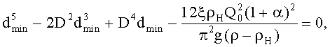
1. Способ понижения дебита аварийных фонтанирующих скважин, заключающийся в том, что непосредственно в эксплуатационную скважину подают шары из материала, имеющего плотность больше плотности нефти до образования пробки на забое, отличающийся тем, что подачу ведут либо шаров из цельного минерала или металла, либо изготовленных из такого же материала удлиненных тел вращения обтекаемой формы со смещенным центром тяжести вдоль оси, при этом диаметр шаров и диаметр миделева сечения удлиненных тел вращения выбирают больше минимального значения, которое определяют из решения приближенного уравнения ! ! где dmin - минимальный диаметр шаров, м; ! D - диаметр скважины, м; ! ξ - коэффициент сопротивления; ! ρH - плотность нефти, кг/м3; ! Q0 - начальный дебит нефти фонтанирующей скважины, м3/с; ! α - газовое число (отношение объемных расходов газа и нефти); ! g - ускорение свободного падения, м/с2; ! ρ - плотность материала шара, кг/м3, ! и меньше максимального значения, которое определяют из решения приближенного уравнения ! , ! где , причем процесс ведут до полного заполнения скважины или до достижения приемлемого размера дебита. ! 2. Способ по п.1, отличающийся тем, что для удлиненных тел вращения выбирают форму в виде усеченного конуса, боковая поверхность которого сопряжена с соответствующими частями сфер по торцам. ! 3. Способ по п.1, отличающийся тем, что диаметр шаров и миделевого сечения удлиненных тел вращения выбирают в пределах неравенства ! D/3-Δ≤d<D/3, ! где d - диаметр шаров и удлиненных тел вращения, м, ! Δ - допуск на диаметр шаров и удлиненных тел вращения при изготовлении, м. !4. Способ по п.1, отличающийся тем, что для заполнения ниж� 1. A method of reducing the flow rate of emergency flowing wells, which consists in directly supplying balls from a material having a density higher than the density of the oil to the formation of a cork in the bottom hole, characterized in that either the balls are made of solid mineral or metal, or made of the same material of elongated streamlined bodies of revolution of a streamlined shape with a displaced center of gravity along the axis, while the diameter of the balls and the diameter of the mid-section of the elongated bodies of revolution are chosen greater than the minimum value tions, which is determined from the solution of the approximate equation! ! where dmin is the minimum diameter of the balls, m; ! D is the diameter of the well, m; ! ξ is the resistance coefficient; ! ρH - oil density, kg / m3; ! Q0 is the initial flow rate of oil flowing wells, m3 / s; ! α is the gas number (the ratio of the volumetric flow rates of gas and oil); ! g is the acceleration of gravity, m / s2; ! ρ is the density of the ball material, kg / m3,! and less than the maximum value, which is determined from the solution of the approximate equation! ! where, and the process is conducted until the well is completely filled or until an acceptable production rate is reached. ! 2. The method according to claim 1, characterized in that for elongated bodies of revolution, a shape in the form of a truncated cone is selected, the lateral surface of which is associated with the corresponding parts of the spheres at the ends. ! 3. The method according to claim 1, characterized in that the diameter of the balls and the mid-section of the elongated bodies of revolution are chosen within the inequality! D / 3-Δ≤d <D / 3,! where d is the diameter of the balls and elongated bodies of revolution, m,! Δ - tolerance on the diameter of the balls and elongated bodies of revolution during manufacture, m.! 4. The method according to claim 1, characterized in that to fill the bottom
Claims (5)

Priority Applications (1)
| Application Number | Priority Date | Filing Date | Title |
|---|---|---|---|
| RU2010143043/03A RU2482262C2 (en) | 2010-10-20 | Method for decreasing flow rate of emergency flowing wells |
Applications Claiming Priority (1)
| Application Number | Priority Date | Filing Date | Title |
|---|---|---|---|
| RU2010143043/03A RU2482262C2 (en) | 2010-10-20 | Method for decreasing flow rate of emergency flowing wells |
Publications (2)
| Publication Number | Publication Date |
|---|---|
| RU2010143043A true RU2010143043A (en) | 2012-04-27 |
| RU2482262C2 RU2482262C2 (en) | 2013-05-20 |
Family
ID=
Similar Documents
| Publication | Publication Date | Title |
|---|---|---|
| US8936093B2 (en) | Controlled rise velocity bouyant ball assisted hydrocarbon lift system and method | |
| CN104234677B (en) | A method for enhancing condensate oil recovery in condensate gas reservoirs by vertical displacement of gas injection | |
| CN110991760B (en) | Method for predicting critical carrier flow rate of high gas-liquid ratio water-gas well | |
| CN106401535B (en) | A kind of method of determining coal bed gas well mining intensity | |
| CN104057081B (en) | Dissoluble metal material for underground construction | |
| RU2010143043A (en) | METHOD FOR DECREASING THE DEBIT OF EMERGENCY FILLING WELLS | |
| CN104533346A (en) | Method for preparing hole flushing agent through citric acid in in-situ leaching uranium mining process | |
| WO2016094267A1 (en) | Solution mining a stable roof under an inert gas | |
| CN108397172A (en) | The CO of high saturation pressure oil reservoir2Miscible displacement of reservoir method | |
| CN206016790U (en) | Limited level discontinuous Double helix shaft bottom sand liquid mixture tubing string | |
| CN104232927B (en) | Oxygen free copper production dehydrogenation deoxidation method | |
| CN103352660B (en) | Half-funnel-type nozzle double-layer water channel diamond-impregnated bit | |
| CN104404912A (en) | Method for arranging rock plug for rock plug exploding model test | |
| CN203772159U (en) | Deep hole blasting upper decoupling charge structure | |
| CN104722139A (en) | Water separator for preventing hydrogen induced cracking | |
| US20150083390A1 (en) | Controlled Rise Velocity Buoyant Ball Assisted Hydrocarbon Lift System and Method | |
| CN101698465B (en) | Floating ball funnel | |
| CN106111908B (en) | A kind of equipment and application method for preventing molten casting iron overflow everywhere | |
| CN105426621B (en) | Determination method of spring elastic coefficient of single-flow valve for oil well stratified production | |
| CN201102974Y (en) | Novel aluminum-iron combined deoxidized agent block | |
| RU2482262C2 (en) | Method for decreasing flow rate of emergency flowing wells | |
| JP2011189379A (en) | Stalk for low pressure casting and low pressure casting method | |
| RU2451788C2 (en) | Method to suppress spills from emergency oil and gas wells during field development | |
| CN204186822U (en) | Spiral accelerates pipeline | |
| CN102528009B (en) | A kind of continuous-casting opening-assisting plug |