RU190876U1 - COMBINED SEEDING UNIT - Google Patents
COMBINED SEEDING UNIT Download PDFInfo
- Publication number
- RU190876U1 RU190876U1 RU2019108556U RU2019108556U RU190876U1 RU 190876 U1 RU190876 U1 RU 190876U1 RU 2019108556 U RU2019108556 U RU 2019108556U RU 2019108556 U RU2019108556 U RU 2019108556U RU 190876 U1 RU190876 U1 RU 190876U1
- Authority
- RU
- Russia
- Prior art keywords
- shaped
- rods
- frame
- paw
- stand
- Prior art date
Links
Images
Classifications
-
- A—HUMAN NECESSITIES
- A01—AGRICULTURE; FORESTRY; ANIMAL HUSBANDRY; HUNTING; TRAPPING; FISHING
- A01B—SOIL WORKING IN AGRICULTURE OR FORESTRY; PARTS, DETAILS, OR ACCESSORIES OF AGRICULTURAL MACHINES OR IMPLEMENTS, IN GENERAL
- A01B49/00—Combined machines
Landscapes
- Life Sciences & Earth Sciences (AREA)
- Engineering & Computer Science (AREA)
- Mechanical Engineering (AREA)
- Soil Sciences (AREA)
- Environmental Sciences (AREA)
- Sowing (AREA)
Abstract
Полезная модель относится к сельскохозяйственному машиностроению, в частности к сеялкам для посева зерновых культур.Комбинированный посевной агрегат включает раму с прицепным устройством, бункер с высевающими аппаратами, опорные колеса, сошники. Каждый сошник содержит стойку, лапу и тукопровод. По оси симметрии лапы установлена ножевидная стойка, передняя грань которой двусторонне заострена и острием направлена в сторону движения сошника. Тукопровод установлен между крыльями лапы за ножевидной стойкой. Сзади тукопровода установлены почвоотводящие крылья. С задней части стойки установлены кронштейн, штанга с пружиной и семяпровод. За сошниками установлен каток. С задней частью рамы жестко закреплены Г-образные кронштейны с направляющими втулками. В направляющих втулках установлены штанги с пружинами. Под Г-образными кронштейнами установлена П-образная рама. Прикатывающий каток установлен в П-образной раме. Штанги одним концом шарнирно установлены на продольных балках П-образной рамы, другим - в направляющих втулках, с возможностью вертикального перемещения штанг в направляющих втулках. Прикатывающий каток содержит ось, боковые и промежуточные диски, и прутки. По периферии боковых и промежуточных дисков с равным угловым шагом выполнены выемки в виде полукруга. Боковые и промежуточные диски установлены на оси через равные интервалы в горизонтальной плоскости и со смещением друг относительно друга в вертикальной плоскости. Прутки установлены в выемках таким образом, что образуют многозаходную винтовую линию, а в поперечном сечении прутки имеют форму многогранника.Такое конструктивное исполнение комбинированного посевного агрегата позволит повысить качество посева зерновых культур.The utility model relates to agricultural machinery, in particular to seeders for sowing grain crops. The combined sowing unit includes a frame with a towing device, a hopper with sowing devices, support wheels, coulters. Each coulter contains a stand, a paw and a tukovod. A knife-shaped stand is installed along the axis of symmetry of the paw, the front face of which is bilaterally pointed and pointed toward the movement of the opener. The tubing is installed between the wings of the paw behind the knife-shaped stand. Rear fenders are installed behind the tukoprovod. A bracket, a spring bar and a seed tube are installed at the rear of the rack. Behind the coulters mounted skating rink. With the back of the frame rigidly fixed L-shaped brackets with guide bushings. In the guide bushings installed rod with springs. Under the L-shaped brackets installed U-shaped frame. The press roller is installed in the U-shaped frame. The rods are hinged at one end on the longitudinal beams of the U-shaped frame, the other in the guide bushes, with the possibility of vertical movement of the rods in the guide bushes. The packer roller contains an axle, side and intermediate discs, and rods. On the periphery of the side and intermediate disks with equal angular pitch, recesses are made in the form of a semicircle. The lateral and intermediate disks are mounted on the axis at equal intervals in the horizontal plane and offset from each other in the vertical plane. The rods are installed in the grooves in such a way that they form a multiple helix, and in cross-section the rods have the shape of a polyhedron. Such a design embodiment of the combined sowing unit will improve the quality of sowing crops.
Description
Полезная модель относится к сельскохозяйственному машиностроению, в частности, к сеялкам для посева зерновых культур.The utility model relates to agricultural engineering, in particular, to seed drills for sowing crops.
Известен комбинированный посевной агрегат [Патент RU №2293460. - Опубл. 20.02.2007 г., Бюл. №5], включающий раму с прицепным устройством, бункер с высевающими аппаратами, опорные колеса, сошники. Сзади сеялки установлены катки.Known combined sowing unit [Patent RU No. 2293460. - Publ. 20.02.2007, Byul. No. 5], which includes a frame with a hitch, a bunker with sowing devices, support wheels, coulters. Rollers are installed behind the drill.
Однако известный посевной агрегат имеет недостаток, к которому можно отнести невозможность высева семян и удобрений на разную глубину, а также низкое качество разрушения комков почвы в процессе посева.However, the known sowing unit has a disadvantage, which can be attributed to the impossibility of sowing seeds and fertilizers at different depths, as well as the poor quality of the destruction of soil lumps during sowing.
Технический результат полезной модели - повышение качества посева зерновых культур.The technical result of the utility model - improving the quality of sowing crops.
Технический результат достигается тем, что каждый сошник содержит стойку, лапу и тукопровод, по оси симметрии лапы устанавливают ножевидную стойку, переднюю грань которой двусторонне заостряют и острием направляют в сторону движения сошника. Стойку устанавливают в верхней части ножевидной стойки. Тукопровод устанавливают между крыльями лапы за ножевидной стойкой. Выходное отверстие тукопровода направляют в подлаповое пространство лапы. Сзади тукопровода установлены почвоотводящие крылья. С задней части стойки устанавливают кронштейн, штангу с пружиной и семяпровод. Семяпровод устанавливают в кронштейне с возможностями изменения положения по высоте относительно режущих кромок крыльев лапы и давления на почву. С нижней части семяпровода жестко устанавливают клиновидный наконечник и острием направляют в сторону движения сошника, а выходные отверстия семяпровода и тукопровода располагают друг от друга на расстоянии, равном требуемой разнице по глубине заделки семян и удобрений. За сошниками устанавливают прикатывающий каток. С задней частью рамы комбинированного посевного агрегата жестко закрепляют Г-образные кронштейны с направляющими втулками. В направляющих втулках устанавливают штанги и снабжают пружинами. Под Г-образными кронштейнами устанавливают П-образная раму, а в П-образной раме устанавливают прикатывающий каток. Г-образные кронштейны располагают вдоль продольных балок П-образной рамы на одинаковом расстоянии от продольной оси симметрии прикатывающего катка. Штанги одним концом шарнирно устанавливают на продольных балках П-образной рамы, другим - в направляющих втулках, с возможностью вертикального перемещения штанг в направляющих втулках, а место установки штанг на продольных балках совпадает с продолжением геометрической оси вращения прикатывающего катка. Прикатывающий каток содержит ось, боковые и промежуточные диски, и прутки. По периферии боковых и промежуточных дисков с равным угловым шагом выполняют выемки в виде полукруга. Боковые и промежуточные диски устанавливают на оси через равные интервалы в горизонтальной плоскости и со смещением друг относительно друга в вертикальной плоскости, причем прутки устанавливают в выемках таким образом, что образуют многозаходную винтовую линию, а в поперечном сечении прутки имеют форму многогранника.The technical result is achieved by the fact that each coulter contains a stand, a paw and a pipeline, the knife-shaped stand is established along the axis of symmetry of the paw, the front edge of which is bilaterally pointed and pointed with the edge in the direction of the movement of the coulter. The rack is installed in the upper part of the knife-shaped rack. The tubing is installed between the wings of the paw behind the knife-shaped stand. The exit of the tukoprovod is directed to the subflat paw space. Rear fenders are installed behind the tukoprovod. A bracket, a spring bar and a seed tube are installed from the back of the rack. The seed tube is installed in the bracket with the possibility of changing the position in height relative to the cutting edges of the wings of the paw and pressure on the soil. From the bottom of the seed tube, a wedge-shaped tip is rigidly installed and the tip is directed toward the coulter's movement, and the outlet holes of the seed tube and the tube line are spaced from each other at a distance equal to the required difference in the depth of embedding of seeds and fertilizers. Behind the coulters install the press roller. With the back of the frame of the combined seeding unit rigidly fixed L-shaped brackets with guide bushings. In the guide bushings install rods and supply springs. Under the L-shaped brackets set U-shaped frame, and in the U-shaped frame install the packer roller. L-shaped brackets have along the longitudinal beams of the U-shaped frame at the same distance from the longitudinal axis of symmetry of the press roller. The rods are pivotally mounted at one end on the longitudinal beams of the U-shaped frame, the other in the guide bushes, with the possibility of vertical movement of the rods in the guide bushes, and the installation site of the rods on the longitudinal beams coincides with the continuation of the geometrical axis of rotation of the press roller. The packer roller contains an axle, side and intermediate discs, and rods. On the periphery of the side and intermediate disks with equal angular pitch perform the notches in the form of a semicircle. Side and intermediate discs are mounted on the axis at regular intervals in the horizontal plane and offset from each other in the vertical plane, with the rods set in the grooves in such a way that they form a multiple helix, and in cross section the rods have a polyhedron shape.
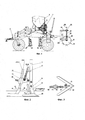
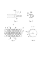
На фиг. 1 изображен комбинированный посевной агрегат, вид сбоку, на фиг. 2 - сошник, вид сбоку, на фиг. 3 - сошник, вид сверху, на фиг. 4 - сечение сошника по линии А-А, на фиг 5 - сечение семяпровода по линии Б-Б, на фиг. 6 - прикатывающий каток, вид В, на фиг. 7 - сечение прикатывающего катка по линии Г-Г.FIG. 1 shows a combined sowing unit, side view, FIG. 2 — opener, side view; FIG. 3 - opener, top view, in FIG. 4 is the section of the vomer along the line A-A, in FIG. 5 is the section of the seed line along the line BB, in FIG. 6 - press roller, view B, in FIG. 7 is a cross-section of the packer roller along the GG line.
Комбинированный посевной агрегат содержит раму 1 с прицепным устройством 2. В центральной части рамы 1 установлен бункер 3 с семявысевающими 4 и туковысевающими 5 аппаратами. На раме 1 установлены опорные колеса 6 и 6*. Вращение семя- и туковысевающих аппаратов 4 и 5 осуществляют от опорного колеса 6 посредством привода 7. На раме 1 установлены сошники 8 в шахматном порядке.The combined sowing unit contains a frame 1 with a
Каждый сошник 8 содержит стойку 9, лапу 10 и тукопровод 11. По оси симметрии лапы 10 установлена ножевидная стойка 12, передняя грань которой двусторонне заострена и острием направлена в сторону движения посевного агрегата. Стойка 9 установлена в верхней части ножевидной стойки 12. Тукопровод 11 установлен между крыльями лапы 10 за ножевидной стойкой 12. Выходное отверстие тукопровода 11 направлено в подлаповое пространство лапы 10. Сзади тукопровода 11 установлены почвоотводящие крылья 13. С задней части стойки 9 установлены кронштейн 14 с фиксатором 15, штанга 16 с пружиной 17 и гайкой 18 и семяпровод 19. Семяпровод 19 установлен в кронштейне 14 с возможностями изменения положения по высоте относительно режущих кромок крыльев лапы 10 и давления на почву. Требуемое положение семяпровода 19 в кронштейне 14 фиксируют посредством фиксатора 15 вворачиваемого в кронштейн 14. С нижней части семяпровода 19 жестко установлен клиновидный наконечник 20 и острием направлен в сторону движения сошника, а выходные отверстия семяпровода 19 и тукопровода 11 расположены друг от друга на расстоянии, равном требуемой разнице по глубине заделки семян и удобрений.Each
Семя- и туковысевающие аппараты 4 и 5 соединены с семя- и тукопроводами 19 и 11 сошников 8 посредством гибких шлангов (на фиг. не показаны).The seed and
На раме 1 за сошниками 8 установлен каток 21. С задней частью рамы 1 комбинированного посевного агрегата жестко закреплены Г-образные кронштейны 22 с направляющими втулками 23. В направляющих втулках 23 установлены штанги 24. Штанги 24 снабжены пружинами 25. В нижних частях штанг 24 установлены гайки 26 с возможностями их перемещения вдоль штанг 24. Под Г-образными кронштейнами 22 установлена П-образная рама 27, а в П-образной раме 27 установлен прикатывающий каток 21 с возможностями колебаний в вертикальной плоскости и регулирования давления на почву. Г-образные кронштейны 22 расположены вдоль продольных балок П-образной рамы 27 на одинаковом расстоянии от продольной оси симметрии прикатывающего катка 21. Штанги 24 одним концом шарнирно, при помощи пальцев 28, установлены на продольных балках П-образной рамы 27, другим - в направляющих втулках 23, с возможностью вертикального перемещения штанг 24 в направляющих втулках 23, а место установки штанг 24 на продольных балках П-образной рамы 27 совпадает с продолжением геометрической оси вращения прикатывающего катка 21. Поперечная балка П-образной рамы 27 шарнирно, при помощи пальцев 29, соединена с Г-образными кронштейнами 22.On frame 1, a
Прикатывающий каток 21 содержит ось 30, боковые 31 и промежуточные 32 диски, и прутки 33. По периферии боковых 31 и промежуточных 32 дисков с равным угловым шагом выполнены выемки в виде полукруга. Боковые 31 и промежуточные 32 диски установлены на оси 30 через равные интервалы в горизонтальной плоскости и со смещением друг относительно друга в вертикальной плоскости. Прутки 33 установлены в выемках боковых 31 и промежуточных 32 дисков таким образом, что образуют многозаходную винтовую линию, а в поперечном сечении прутки 33 имеют форму многогранника.The
Комбинированный посевной агрегат работает следующим образом.Combined seeding unit works as follows.
Предварительно, при помощи прицепного устройства 2 посевной агрегат сцепляют с трактором. При помощи семя- и туковысевающих аппаратов 4 и 5 и привода 7 устанавливают требуемую норму высева семян и удобрений. Устанавливают требуемую глубину хода лап 10 сошников 8. Добиваются, чтобы лезвия лап 10 лежали в горизонтальной плоскости, т.к. при этом обеспечивается ровное дно борозды, лучшее подрезание сорных растений и одинаковую глубину заделки семян и удобрений. Закручиванием или откручиванием гаек 18, расположенных на штангах 16 сошников 8, добиваются необходимого сжатия или растяжения пружин 17, тем самым, регулируя давление семяпровода 11 на почву и, соответственно, его глубину погружения в почву. Регулировкой усилия сжатия пружин 25 устанавливают необходимое давление прикатывающего катка 21 на почву.Previously, with the help of a
При движении комбинированного посевного агрегата заостренные передние грани ножевидных стоек 12 сошников 8 разрезают верхний слой почвы и сдвигают его в междурядье. Лапы 10 сошников 8 рыхлят почву и подрезают сорные растения. Семя- и туковысевающие аппараты 4 и 5 посевного агрегата направляют семена и удобрения к семяпроводам 19 и тукопроводам 11, выходные отверстия которых расположены на разной высоте, причем линия высева удобрений располагается ниже линии высеянных семян. Высеянные удобрения и семена присыпаются слоем почвы, сходящим с крыльев лап 10 и клиновидного наконечника 20.When the combined sowing unit is moving, the pointed front edges of the knife-
Прикатывающий каток 21, при вращении, при вращении, копирует рельеф поверхности поля и прутками 33 интенсивно мульчирует неразрушенные комки почвы с одновременным выравниванием и уплотнением поверхности поля, подтягивая влагу из нижних слоев почвы к верхним слоям. При этом максимальный размер разрезанных комков почвы не превышает максимальных размеров комков почвы, допускаемых агротехническими требованиями к посеву.The rolling
Установка сошников 8 на раме 1 посевного агрегата в шахматном порядке позволяет разрыхлить и подрезать сорные растения на поверхности поля без огрехов за счет перекрытия крыльев лап 10.Installing the
Установка по оси симметрии лапы 10 ножевидной стойки 12, передняя грань которой двусторонне заострена, позволяет исключить сгруживание почвы перед стойкой 9 (как это происходит у серийных стрельчатых лап), и равномерно направить поток подрезанного слоя почвы на высеянные удобрения.Installation along the axis of symmetry of the
Установка с задней части стойки 9 кронштейна 14, штанги 16 с пружиной 17 и семяпровода 19, причем семяпровод 19 установлен в кронштейне 14, позволяет высевать семена в почву и располагать их размещение выше высеянных удобрений.Installation from the rear of the
Наличие клиновидного наконечника 20, острие которого направлено в сторону движения сошника, позволяет гарантированно исключить забивание выходного отверстия семяпровода 19, что непосредственно влияет на качество посева сельскохозяйственных культур.The presence of the wedge-shaped
Повышение качества посева достигается за счет установки тукопровода 11 и семяпровода 19 таким образом, что их выходные отверстия расположены друг от друга на расстоянии, равном требуемой разнице по глубине заделки семян и удобрений, что также позволяет семенам и удобрениям качественно укладываться в почву на разной высоте.Improving the quality of sowing is achieved by installing the
Наличие штанг 16 с пружинами 17 и гайками 18 позволяет семяпроводу 19 копировать рельеф поверхности поля и, соответственно, заделывать семена на одинаковую глубину от уровня поверхности поля.The presence of
Наличие прикатывающего катка 21, содержащего ось 30, боковые 31 и. промежуточные 32 диски, и прутки 33 позволяет не только с высоким качеством разрушить комки почвы, оставшиеся после прохода сошников 8, но и равномерно уплотнить почву с заданной агротехническими требованиями плотностью.The presence of the
Наличие штанг 24 с пружинами 25 и гайками 26 позволяет катку 21, при его вращении, копировать рельеф поверхности поля и, соответственно, равномерно уплотнять почву.The presence of
Установка боковых 31 и промежуточных 32 дисков на оси 30 через равные интервалы в горизонтальной плоскости позволяет исключить прогиб прутков 33 в сторону оси 30 прикатывающего катка 21 при взаимодействии их с твердыми комками на поверхности почвы.Installing the
Установка боковых 31 и промежуточных 32 дисков на оси 30 со смещением друг относительно друга в вертикальной плоскости, причем прутки 33 установлены в выемках боковых 31 и промежуточных 32 дисков таким образом, что образуют многозаходную винтовую линию, позволяет пруткам 33 внедряться в почву плавно и без удара, исключить вибрации и «подпрыгивания» прикатывающего катка 21.Installing the
Выполнение прутков 33 в поперечном сечении многогранными - позволяет пруткам 33 своими гранями, при взаимодействии с комками почвы, с наименьшими затратами энергии наиболее качественно разрушить комки почвы.The implementation of the
Установка прикатывающего катка 21 в П-образной раме 27 с возможностями совершения колебаний в вертикальной плоскости и регулирования давления на почву, и, с учетом того, что Г-образные кронштейны 22 расположены вдоль продольных балок П-образной рамы 27 на одинаковом расстоянии от продольной оси симметрии прикатывающего катка 21, а место установки штанг 24 на продольных балках совпадает с продолжением геометрической оси вращения прикатывающего катка 21, позволяет прикатывающему катку 21 без перекосов копировать рельеф поверхности поля всей рабочей поверхностью и, соответственно, с требуемым усилием равномерно уплотнять почву.Installing the
Это повышает качество посева, обеспечивает наилучший контакт семян с почвой и улучшает температурный, водный и воздушный условия для развития растений.This improves the quality of sowing, provides the best contact of seeds with the soil and improves the temperature, water and air conditions for plant development.
Claims (1)
Priority Applications (1)
| Application Number | Priority Date | Filing Date | Title |
|---|---|---|---|
| RU2019108556U RU190876U1 (en) | 2019-03-25 | 2019-03-25 | COMBINED SEEDING UNIT |
Applications Claiming Priority (1)
| Application Number | Priority Date | Filing Date | Title |
|---|---|---|---|
| RU2019108556U RU190876U1 (en) | 2019-03-25 | 2019-03-25 | COMBINED SEEDING UNIT |
Publications (1)
| Publication Number | Publication Date |
|---|---|
| RU190876U1 true RU190876U1 (en) | 2019-07-16 |
Family
ID=67309805
Family Applications (1)
| Application Number | Title | Priority Date | Filing Date |
|---|---|---|---|
| RU2019108556U RU190876U1 (en) | 2019-03-25 | 2019-03-25 | COMBINED SEEDING UNIT |
Country Status (1)
| Country | Link |
|---|---|
| RU (1) | RU190876U1 (en) |
Cited By (4)
| Publication number | Priority date | Publication date | Assignee | Title |
|---|---|---|---|---|
| RU196916U1 (en) * | 2020-01-27 | 2020-03-19 | Федеральное государственное бюджетное образовательное учреждение высшего образования "Ульяновский государственный аграрный университет имени П.А. Столыпина" | COMBINED SEED UNIT |
| RU197060U1 (en) * | 2020-01-20 | 2020-03-26 | Федеральное государственное бюджетное образовательное учреждение высшего образования "Ульяновский государственный аграрный университет имени П.А. Столыпина" | COMBINED SEED UNIT |
| RU197864U1 (en) * | 2020-02-12 | 2020-06-03 | Федеральное государственное бюджетное образовательное учреждение высшего образования "Ульяновский государственный аграрный университет имени П.А. Столыпина" | COMBINED SEED UNIT |
| RU197863U1 (en) * | 2020-02-12 | 2020-06-03 | Федеральное государственное бюджетное образовательное учреждение высшего образования "Ульяновский государственный аграрный университет имени П.А. Столыпина" | COMBINED SEED UNIT |
Citations (4)
| Publication number | Priority date | Publication date | Assignee | Title |
|---|---|---|---|---|
| US4601248A (en) * | 1984-06-13 | 1986-07-22 | North Carolina State University | Minimum tillage planting apparatus |
| US4624197A (en) * | 1982-11-22 | 1986-11-25 | Denny Drake | Minimum tillage toolbar and method for using same |
| RU2293460C2 (en) * | 2004-05-19 | 2007-02-20 | ЗАО "Павловск-Агроснаб-Холдинг" | Drill |
| RU180168U1 (en) * | 2018-01-11 | 2018-06-05 | Федеральное государственное бюджетное образовательное учреждение высшего образования "Ульяновский государственный аграрный университет имени П.А. Столыпина" | COMBINED SEED UNIT |
-
2019
- 2019-03-25 RU RU2019108556U patent/RU190876U1/en not_active IP Right Cessation
Patent Citations (4)
| Publication number | Priority date | Publication date | Assignee | Title |
|---|---|---|---|---|
| US4624197A (en) * | 1982-11-22 | 1986-11-25 | Denny Drake | Minimum tillage toolbar and method for using same |
| US4601248A (en) * | 1984-06-13 | 1986-07-22 | North Carolina State University | Minimum tillage planting apparatus |
| RU2293460C2 (en) * | 2004-05-19 | 2007-02-20 | ЗАО "Павловск-Агроснаб-Холдинг" | Drill |
| RU180168U1 (en) * | 2018-01-11 | 2018-06-05 | Федеральное государственное бюджетное образовательное учреждение высшего образования "Ульяновский государственный аграрный университет имени П.А. Столыпина" | COMBINED SEED UNIT |
Cited By (4)
| Publication number | Priority date | Publication date | Assignee | Title |
|---|---|---|---|---|
| RU197060U1 (en) * | 2020-01-20 | 2020-03-26 | Федеральное государственное бюджетное образовательное учреждение высшего образования "Ульяновский государственный аграрный университет имени П.А. Столыпина" | COMBINED SEED UNIT |
| RU196916U1 (en) * | 2020-01-27 | 2020-03-19 | Федеральное государственное бюджетное образовательное учреждение высшего образования "Ульяновский государственный аграрный университет имени П.А. Столыпина" | COMBINED SEED UNIT |
| RU197864U1 (en) * | 2020-02-12 | 2020-06-03 | Федеральное государственное бюджетное образовательное учреждение высшего образования "Ульяновский государственный аграрный университет имени П.А. Столыпина" | COMBINED SEED UNIT |
| RU197863U1 (en) * | 2020-02-12 | 2020-06-03 | Федеральное государственное бюджетное образовательное учреждение высшего образования "Ульяновский государственный аграрный университет имени П.А. Столыпина" | COMBINED SEED UNIT |
Similar Documents
| Publication | Publication Date | Title |
|---|---|---|
| RU190018U1 (en) | COMBINED SEEDING UNIT | |
| RU190286U1 (en) | COMBINED SEEDING UNIT | |
| RU189432U1 (en) | COMBINED SEEDING UNIT | |
| RU190876U1 (en) | COMBINED SEEDING UNIT | |
| RU190908U1 (en) | COMBINED SEEDING UNIT | |
| RU190283U1 (en) | COMBINED SEEDING UNIT | |
| RU190288U1 (en) | COMBINED SEEDING UNIT | |
| RU194360U1 (en) | COMBINED SEED UNIT | |
| RU190466U1 (en) | COMBINED SEEDING UNIT | |
| RU190027U1 (en) | COMBINED SEEDING UNIT | |
| RU190025U1 (en) | COMBINED SEEDING UNIT | |
| RU190304U1 (en) | COMBINED SEEDING UNIT | |
| RU189980U1 (en) | COMBINED SEEDING UNIT | |
| RU190284U1 (en) | COMBINED SEEDING UNIT | |
| RU190969U1 (en) | COMBINED SEEDING UNIT | |
| RU199187U1 (en) | COMBINED SEEDING UNIT | |
| RU190924U1 (en) | COMBINED SEEDING UNIT | |
| RU189760U1 (en) | COMBINED SEEDING UNIT | |
| RU199371U1 (en) | COMBINED SEEDING UNIT | |
| RU189979U1 (en) | COMBINED SEEDING UNIT | |
| RU194805U1 (en) | COMBINED SEED UNIT | |
| RU190874U1 (en) | COMBINED SEEDING UNIT | |
| RU190032U1 (en) | COMBINED SEEDING UNIT | |
| RU189599U1 (en) | COMBINED SEEDING UNIT | |
| RU190026U1 (en) | COMBINED SEEDING UNIT |
Legal Events
| Date | Code | Title | Description |
|---|---|---|---|
| MM9K | Utility model has become invalid (non-payment of fees) |
Effective date: 20190714 |