RU190841U1 - DEVICE OF WATER FLOW ADJUSTMENT - Google Patents
DEVICE OF WATER FLOW ADJUSTMENT Download PDFInfo
- Publication number
- RU190841U1 RU190841U1 RU2019108338U RU2019108338U RU190841U1 RU 190841 U1 RU190841 U1 RU 190841U1 RU 2019108338 U RU2019108338 U RU 2019108338U RU 2019108338 U RU2019108338 U RU 2019108338U RU 190841 U1 RU190841 U1 RU 190841U1
- Authority
- RU
- Russia
- Prior art keywords
- tank
- valve
- water
- weight
- hinge
- Prior art date
Links
Images


Classifications
-
- F—MECHANICAL ENGINEERING; LIGHTING; HEATING; WEAPONS; BLASTING
- F16—ENGINEERING ELEMENTS AND UNITS; GENERAL MEASURES FOR PRODUCING AND MAINTAINING EFFECTIVE FUNCTIONING OF MACHINES OR INSTALLATIONS; THERMAL INSULATION IN GENERAL
- F16K—VALVES; TAPS; COCKS; ACTUATING-FLOATS; DEVICES FOR VENTING OR AERATING
- F16K5/00—Plug valves; Taps or cocks comprising only cut-off apparatus having at least one of the sealing faces shaped as a more or less complete surface of a solid of revolution, the opening and closing movement being predominantly rotary
- F16K5/06—Plug valves; Taps or cocks comprising only cut-off apparatus having at least one of the sealing faces shaped as a more or less complete surface of a solid of revolution, the opening and closing movement being predominantly rotary with plugs having spherical surfaces; Packings therefor
Abstract
Устройство предназначено для отбора воды под высоким давлением из водопровода и выдачи воды с низким давлением, требуемым расходом и может быть использовано в промышленности, системах очистки, геотехнологии.Техническим результатом предлагаемой полезной модели является снижение габаритов и веса устройства при увеличении усилия, прилагаемого к клапану, а также повышение надежности. Технический результат достигается тем, что устройство регулировки потока воды, содержащее клапан, соединенный с трубой подачи воды, (наполняемый) бак, механизм передачи веса бака к клапану, устройство слива воды, характеризуется тем, что механизм передачи веса бака к клапану выполнен таким образом, что вес воды, заполняющей бак приводит к закрыванию клапана.Клапан может представлять собой подвижную площадку, соединенную с подвижной частью бака, расположенную напротив седла, стационарного отверстия на конце подводящего трубопровода, направление движения подвижной площадки по существу перпендикулярно плоскости отверстия. Бак одним концом может быть соединен c шарниром, клапан соединен непосредственно с баком, на расстоянии от шарнира. Бак может быть также установлен на шарнире посредством кронштейна. Бак одним концом может соединяться c шарниром, устройство передачи веса клапана представляет собой рычажный механизм со стационарно закрепленной осью рычага, к одному плечу которого механически прикреплена тяга, соединенная с баком, а к другому плечу присоединена подвижная часть клапана. Слив воды из бака может производиться регулятором расхода воды, соединенным с дном бака. В качестве регулятора расхода воды может использоваться кран, калиброванная втулка и т.д. Устройство может дополнительно содержать устройство компенсации веса бака, например противовес или пружину. Устройство может дополнительно содержать устройство предотвращения волнообразного движения воды в баке, например перегородки, пористый наполнитель и т.д.Заявленное устройство может с успехом применяться для обеспечения стабильного уровня воды в баке и обеспечения стабильного расхода воды.The device is designed for high-pressure water extraction from the water supply system and for the delivery of low-pressure water at the required flow rate and can be used in industry, purification systems, and geotechnology. The technical result of the proposed utility model is to reduce the size and weight of the device while increasing the force applied to the valve, and also increase in reliability. The technical result is achieved in that the device for regulating the flow of water, containing a valve connected to the water supply pipe, (refillable) tank, a mechanism for transmitting the weight of the tank to the valve, a device for draining the water, is characterized in that the mechanism for transmitting the weight of the tank to the valve is made in such a way that the weight of the water filling the tank causes the valve to close. The valve may be a movable platform connected to the movable part of the tank, located opposite the seat, a stationary hole at the end of the supply pipe, e.g. The motion of the movable platform is substantially perpendicular to the plane of the hole. The tank at one end can be connected to the hinge, the valve is connected directly to the tank, at a distance from the hinge. The tank can also be hinged through a bracket. The tank can be connected to the hinge at one end, the valve weight transfer device is a lever mechanism with a fixed axis of the lever, to one arm of which a rod is mechanically attached, connected to the tank, and the movable part of the valve is attached to the other shoulder. Water can be drained from the tank by a water flow regulator connected to the bottom of the tank. As a regulator of water flow, a tap, a calibrated sleeve, etc. can be used. The device may further comprise a tank weight compensation device, such as a counterweight or spring. The device may further comprise a device for preventing wave-like movement of water in the tank, for example, partitions, porous filler, etc. The claimed device can be successfully used to ensure a stable level of water in the tank and ensure a stable flow of water.
Description
Устройство предназначено для отбора воды под высоким давлением из водопровода и выдачи воды с низким давлением, требуемым расходом и может быть использовано в промышленности, системах очистки, геотехнологии.The device is designed for the selection of high-pressure water from the water supply system and the delivery of water with low pressure, the required flow rate and can be used in industry, cleaning systems, geotechnology.
Известно «Гидравлическое устройство для наполнения и закрытия унитазного бачка» EP 0251837 [1], содержащее клапан, который открывается под действием веса подвижного контейнера, заполняемого водой.It is known “A hydraulic device for filling and closing a toilet tank” EP 0251837 [1], which contains a valve that opens under the action of the weight of the movable container filled with water.
Недостатками известной конструкции являются повышенная сложность устройства.The disadvantages of the known designs are the increased complexity of the device.
Наиболее близким к заявляемому техническому решению является «Шаровой кран-регулятор» WO 9821512 [2], включающий клапан, соединенный с трубой подачи воды, наполняемый бак, механизм передачи веса бака к клапану, устройство слива воды.Closest to the claimed technical solution is the “Ball valve regulator” WO 9821512 [2], which includes a valve connected to the water supply pipe, a filling tank, a mechanism for transferring the weight of the tank to the valve, a device for draining water.
Известный устройство относительно простое. The known device is relatively simple.
Недостатком известной конструкции является высокие габариты и недостаточное усилие, развиваемое поплавком, действующим на шток, соединенный с клапаном. Также устройство обладает низкой надежностью запирания при повышении давления в подающем трубопроводе.A disadvantage of the known construction is the high dimensions and insufficient force developed by the float acting on the rod connected to the valve. Also, the device has a low reliability of locking with increasing pressure in the supply pipe.
Техническим результатом предлагаемой полезной модели является снижение габаритов и веса устройства при увеличении усилия, прилагаемого к клапану, а также повышение надежности.The technical result of the proposed utility model is to reduce the size and weight of the device with increasing force applied to the valve, as well as increased reliability.
Технический результат достигается тем, что устройство регулировки потока воды, содержащее клапан, соединенный с трубой подачи воды, (наполняемый) бак, механизм передачи веса бака к клапану, устройство слива воды, характеризуется тем, что механизм передачи веса бака к клапану выполнен таким образом, что вес воды заполняющей бак приводит к закрыванию клапана.The technical result is achieved by the fact that a water flow regulation device containing a valve connected to a water supply pipe, a (filled) tank, a mechanism for transferring the weight of the tank to the valve, a device for draining water is characterized in that the mechanism for transferring the weight of the tank to the valve is designed that the weight of the water filling the tank causes the valve to close.
Клапан может представлять собой подвижную площадку, соединенную с подвижной частью бака, расположенную напротив седла, стационарного отверстия на конце подводящего трубопровода, направление движения подвижной площадки по существу перпендикулярно плоскости отверстия. Подвижная площадка, как правило, имеет пластичную поверхность, обращенную к седлу клапана. Указанное выполнение клапана позволяет упростить конструкцию.The valve may be a movable platform connected to the movable part of the tank, located opposite the seat, a stationary opening at the end of the supply pipe, the direction of movement of the movable platform essentially perpendicular to the plane of the opening. The movable platform, as a rule, has a plastic surface facing the valve seat. The specified implementation of the valve allows to simplify the design.
Бак одним концом может быть соединен c шарниром, клапан соединен непосредственно с баком, на расстоянии от шарнира. Бак может быть также установлен на шарнире посредством кронштейна. Расстояние от оси до точки крепления клапана (или привода клапана) определяет величину усилия, передаваемого от бака и воды к клапану, и выбирается по необходимости.The tank at one end can be connected to the hinge, the valve is connected directly to the tank, at a distance from the hinge. The tank can also be mounted on a hinge by means of a bracket. The distance from the axis to the point of attachment of the valve (or valve actuator) determines the amount of force transmitted from the tank and water to the valve, and is selected as needed.
Бак одним концом может соединяться c шарниром, устройство передачи веса клапана представляет собой рычажный механизм со стационарно закрепленной осью рычага, к одному плечу которого механически прикреплена тяга, соединенная с баком, а к другому плечу присоединена подвижная часть клапана. Рычажный механизм позволит облегчить регулировку благодаря простому изменению соотношения длины плеч механизма. The tank at one end can be connected with a hinge, the valve weight transfer device is a lever mechanism with a fixed lever axis, one arm of which is mechanically attached to the thrust connected to the tank, and the other part is connected to the movable part of the valve. The lever mechanism will facilitate the adjustment due to a simple change in the ratio of the length of the arms of the mechanism.
Слив воды из бака может производиться регулятором расхода воды, соединенным с дном бака. В качестве регулятора расхода воды может использоваться кран, калиброванная втулка и т.д.Water can be drained from the tank with a water flow regulator connected to the bottom of the tank. A tap, calibrated bushing, etc. can be used as a water flow regulator.
Устройство может дополнительно содержит устройство компенсации веса бака, например, противовес или пружину. Устройство компенсации веса бака позволит отрегулировать наполнение бака при низком давлении воды в подающем водопроводе, для исключения ситуации, когда вес пустого бака препятствует его наполнению.The device may further comprise a tank weight compensation device, for example, a counterweight or a spring. The device for compensating the weight of the tank will allow you to adjust the filling of the tank with low water pressure in the supply pipe, to avoid a situation where the weight of an empty tank prevents its filling.
Устройство может дополнительно содержать устройство предотвращения волнообразного движения воды в баке, например, перегородки, пористый наполнитель и т.д. Волнообразное движение в баке может привести к нестабильности работы, как подающего водопровода, так и расходной части устройства.The device may further comprise a device for preventing wave-like movement of water in the tank, for example, partitions, porous filler, etc. The undulating movement in the tank can lead to instability in the operation of both the supply pipe and the consumable part of the device.
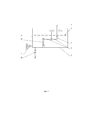
На фиг. 1 изображен вариант выполнения устройства с рычажным механизмом, на фиг. 2 вариант с размещением привода клапана на боковой стенке бака и фиг. 3 вариант с размещением клапана на дне бака, где:FIG. 1 shows an embodiment of a device with a lever mechanism; FIG. 2 with the valve actuator on the side wall of the tank; and FIG. 3 option with the placement of the valve on the bottom of the tank, where:
1 – ось крепления бака;1 - tank mounting axis;
2 – регулятор расхода воды;2 - water flow regulator;
3 – клапан;3 - valve;
4 – стенка бака;4 - tank wall;
5 – дно бака;5 - tank bottom;
6 – уровень воды;6 - water level;
7 – труба подачи воды;7 - water supply pipe;
8 – направление перемещения бака;8 - the direction of movement of the tank;
9 – рычаг со стационарной осью;9 - lever with stationary axis;
10 – тяга рычага.10 - thrust lever.
Устройство действует следующим образом: бак, состоящий из стенок бака 4 и дна бака 5, закреплен на стационарной оси 1. Бак наполняется из трубы подачи воды 7 посредством клапана 3. Вода из бака вытекает через регулятор расхода воды 2. Уровень воды в баке показан поз. 6. Направление перемещения бака 8 (вокруг стационарной оси 1). Для варианта с рычагом 9 одно плечо соединено с клапаном, другое через тягу рычага 10 соединено с баком.The device operates as follows: the tank, consisting of the walls of the
Дросселирующий клапан расположен в баке и подключен к водопроводу, из которого поступает вода под высоким давлением. Бак закреплен на оси и имеет возможность перемещаться по окружности вверх, вниз от горизонтального положения. Дросселирующий клапан прикреплен к корпусу бака таким образом, что при повышении уровня воды в баке возрастает запирающее усилие на клапане, что приводит к уменьшению расхода воды и наоборот.The throttling valve is located in the tank and is connected to the water supply, from which high pressure water flows. The tank is fixed on the axis and has the ability to move around the circle up, down from the horizontal position. A throttling valve is attached to the tank body in such a way that when the water level in the tank rises, the locking force on the valve increases, which leads to a decrease in water consumption and vice versa.
На дне бака имеется сливное отверстие с регулятором расхода воды, через которое сливается вода под давлением уровня воды в баке.At the bottom of the tank there is a drain hole with a water flow regulator through which water is drained under the pressure of the water level in the tank.
Уменьшение расхода воды через регулятор расхода приводит к повышению уровня воды в баке и увеличению запирающей силы на клапане, что приводит к выравниванию расхода воды через регулятор расхода воды и дросселирующий клапан.Reducing the flow of water through the flow regulator leads to an increase in the water level in the tank and an increase in the locking force on the valve, which leads to equalization of the flow of water through the water flow regulator and the throttling valve.
При увеличении расхода воды через регулятор расхода воды приводит к снижению уровня воды в баке и уменьшению запирающей силы на клапане, что приводит к выравниванию расхода воды через регулятор расхода воды и дросселирующий клапан.With an increase in water flow through the water flow regulator, the water level in the tank decreases and the locking force on the valve decreases, which leads to equalization of the water flow through the water flow regulator and the throttling valve.
Для варианта на фиг. 1:For the embodiment of FIG. one:
Клапан установлен на рычаге. Рычаг качается на оси. Седло клапана, ось рычага и ось крепления бака закреплены на общем основании. Рычаг, с противоположной стороны от клапана, тягой прикреплен к дну бака. Больший уровень воды в баке создает большую запирающую силу на клапане.The valve is mounted on the lever. The lever is swinging on the axle. The valve seat, the lever shaft and the tank mounting shaft are fixed on a common base. The lever, on the opposite side of the valve, is attached to the bottom of the tank. A higher water level in the tank creates a greater locking force on the valve.
Для варианта на фиг. 2:For the embodiment of FIG. 2:
Клапан установлен на боковой стенке бака со стороны крепления бака к оси. The valve is installed on the side wall of the tank from the side of the tank to the axis.
Седло клапана и ось крепления бака закреплены на общем основании. Уровень воды в баке действует на клапан аналогичным образомThe valve seat and tank mounting axle are fixed on a common base. The water level in the tank acts on the valve in the same way.
Для варианта на фиг. 3:For the embodiment of FIG. 3:
Клапан закреплен на стойке к дну бака рабочей поверхностью вниз. Седло клапана подведено снизу. Седло клапана и ось крепления бака закреплены на общем основании. Уровень воды в баке действует на клапан аналогичным образомThe valve is mounted on the rack to the bottom of the tank working surface down. Valve seat down from below. The valve seat and tank mounting axle are fixed on a common base. The water level in the tank acts on the valve in the same way.
Технический результат – снижение габаритов и веса устройства при увеличении усилия, прилагаемого к клапану достигается тем, что для формирования усилия используется вес всей жидкости в баке. Повышение надежности достигается упрощением устройства.The technical result is a reduction in size and weight of the device while increasing the force applied to the valve is achieved by using the weight of all the liquid in the tank to form the force. Increased reliability is achieved by simplifying the device.
Промышленное применение. Заявленное устройство может с успехом применяться для обеспечения стабильного уровня воды в баке и обеспечения стабильного расхода воды.Industrial application. The claimed device can be successfully used to ensure a stable water level in the tank and to ensure a stable water flow.
Claims (7)
Priority Applications (1)
| Application Number | Priority Date | Filing Date | Title |
|---|---|---|---|
| RU2019108338U RU190841U1 (en) | 2019-03-22 | 2019-03-22 | DEVICE OF WATER FLOW ADJUSTMENT |
Applications Claiming Priority (1)
| Application Number | Priority Date | Filing Date | Title |
|---|---|---|---|
| RU2019108338U RU190841U1 (en) | 2019-03-22 | 2019-03-22 | DEVICE OF WATER FLOW ADJUSTMENT |
Publications (1)
| Publication Number | Publication Date |
|---|---|
| RU190841U1 true RU190841U1 (en) | 2019-07-15 |
Family
ID=67309833
Family Applications (1)
| Application Number | Title | Priority Date | Filing Date |
|---|---|---|---|
| RU2019108338U RU190841U1 (en) | 2019-03-22 | 2019-03-22 | DEVICE OF WATER FLOW ADJUSTMENT |
Country Status (1)
| Country | Link |
|---|---|
| RU (1) | RU190841U1 (en) |
Citations (5)
| Publication number | Priority date | Publication date | Assignee | Title |
|---|---|---|---|---|
| EP0251837A2 (en) * | 1986-05-29 | 1988-01-07 | Alain Girouard | Hydraulic filling and closing device for a toilet cistern |
| WO1998021512A1 (en) * | 1996-11-09 | 1998-05-22 | Dennis Raymond Henson | Ballcock valve regulator |
| CN205190921U (en) * | 2015-12-14 | 2016-04-27 | 滁州学院 | Mechanical floating -ball water feeding valve |
| CN207514354U (en) * | 2017-10-26 | 2018-06-19 | 良名阀门科技有限公司 | A kind of NEW TYPE OF COMPOSITE lever automatic exhaust steam valve |
| CN207687459U (en) * | 2017-08-25 | 2018-08-03 | 安徽红星阀门有限公司 | A kind of bars,folding parallel bar micro-exhaust valve |
-
2019
- 2019-03-22 RU RU2019108338U patent/RU190841U1/en active
Patent Citations (5)
| Publication number | Priority date | Publication date | Assignee | Title |
|---|---|---|---|---|
| EP0251837A2 (en) * | 1986-05-29 | 1988-01-07 | Alain Girouard | Hydraulic filling and closing device for a toilet cistern |
| WO1998021512A1 (en) * | 1996-11-09 | 1998-05-22 | Dennis Raymond Henson | Ballcock valve regulator |
| CN205190921U (en) * | 2015-12-14 | 2016-04-27 | 滁州学院 | Mechanical floating -ball water feeding valve |
| CN207687459U (en) * | 2017-08-25 | 2018-08-03 | 安徽红星阀门有限公司 | A kind of bars,folding parallel bar micro-exhaust valve |
| CN207514354U (en) * | 2017-10-26 | 2018-06-19 | 良名阀门科技有限公司 | A kind of NEW TYPE OF COMPOSITE lever automatic exhaust steam valve |
Similar Documents
| Publication | Publication Date | Title |
|---|---|---|
| WO2007090039A3 (en) | Water recycling device | |
| RU190841U1 (en) | DEVICE OF WATER FLOW ADJUSTMENT | |
| WO2013148233A1 (en) | Lubricant reservoir refilling system with shut-off | |
| WO2020197443A1 (en) | Device for controlling a water flow | |
| WO1998021512A1 (en) | Ballcock valve regulator | |
| US6123099A (en) | Pinch tube tank level control valve with snap-action shutoff | |
| US4399835A (en) | Water saving toilet control valve | |
| GB2428769A (en) | Flow diverter for fitting to a catchpot-assisted float controlled valve such as a ballcock valve regulator | |
| RU2577681C1 (en) | Hydraulic ram | |
| CA2360859C (en) | Flushing apparatus and method thereof | |
| JPH0326304B2 (en) | ||
| US20090199910A1 (en) | Robust water level control valve | |
| EP2029923B1 (en) | Float valve regulator | |
| KR101178024B1 (en) | A combination jet thrusting water supplier which is operated by ball tap float and a toilet which has the rim water supplier | |
| CN214617857U (en) | Take remote control's intelligent liquid level control device that supplies water | |
| JPS5932775Y2 (en) | Ball tap type automatic water supply device | |
| CN218935400U (en) | Pipeline protection device under medium-pressure environment | |
| CN220320443U (en) | Hydraulic driving mechanism of valve | |
| RU2576095C1 (en) | Hydraulic ram | |
| EA043486B1 (en) | VALVE SYSTEM FOR REGULATING THE LIQUID LEVEL IN A VESSEL (OPTIONS) AND METHOD FOR REGULATING THE LIQUID LEVEL IN A VESSEL USING SUCH A SYSTEM | |
| JP2999996B2 (en) | Float valve interlocking constant flow overflow weir | |
| RU2742148C1 (en) | Installation for automatic plant irrigation | |
| CN213653593U (en) | Intelligent two-water supply device for waterproof hammer | |
| EP3924654B1 (en) | Float valve systems and methods for controlling liquid level in vessels | |
| JP3062544U (en) | Water control valve |
Legal Events
| Date | Code | Title | Description |
|---|---|---|---|
| QB9K | Licence granted or registered (utility model) |
Free format text: LICENCE FORMERLY AGREED ON 20200518 Effective date: 20200518 |