RU188224U1 - Submersible multi-stage vane pump stage - Google Patents
Submersible multi-stage vane pump stage Download PDFInfo
- Publication number
- RU188224U1 RU188224U1 RU2018121560U RU2018121560U RU188224U1 RU 188224 U1 RU188224 U1 RU 188224U1 RU 2018121560 U RU2018121560 U RU 2018121560U RU 2018121560 U RU2018121560 U RU 2018121560U RU 188224 U1 RU188224 U1 RU 188224U1
- Authority
- RU
- Russia
- Prior art keywords
- impeller
- drainage holes
- blades
- stage
- flow channels
- Prior art date
Links
Images
Classifications
-
- F—MECHANICAL ENGINEERING; LIGHTING; HEATING; WEAPONS; BLASTING
- F04—POSITIVE - DISPLACEMENT MACHINES FOR LIQUIDS; PUMPS FOR LIQUIDS OR ELASTIC FLUIDS
- F04D—NON-POSITIVE-DISPLACEMENT PUMPS
- F04D13/00—Pumping installations or systems
- F04D13/02—Units comprising pumps and their driving means
- F04D13/06—Units comprising pumps and their driving means the pump being electrically driven
- F04D13/08—Units comprising pumps and their driving means the pump being electrically driven for submerged use
- F04D13/10—Units comprising pumps and their driving means the pump being electrically driven for submerged use adapted for use in mining bore holes
-
- F—MECHANICAL ENGINEERING; LIGHTING; HEATING; WEAPONS; BLASTING
- F04—POSITIVE - DISPLACEMENT MACHINES FOR LIQUIDS; PUMPS FOR LIQUIDS OR ELASTIC FLUIDS
- F04D—NON-POSITIVE-DISPLACEMENT PUMPS
- F04D29/00—Details, component parts, or accessories
- F04D29/04—Shafts or bearings, or assemblies thereof
- F04D29/041—Axial thrust balancing
-
- F—MECHANICAL ENGINEERING; LIGHTING; HEATING; WEAPONS; BLASTING
- F04—POSITIVE - DISPLACEMENT MACHINES FOR LIQUIDS; PUMPS FOR LIQUIDS OR ELASTIC FLUIDS
- F04D—NON-POSITIVE-DISPLACEMENT PUMPS
- F04D29/00—Details, component parts, or accessories
- F04D29/18—Rotors
- F04D29/22—Rotors specially for centrifugal pumps
- F04D29/2261—Rotors specially for centrifugal pumps with special measures
- F04D29/2266—Rotors specially for centrifugal pumps with special measures for sealing or thrust balance
Abstract
Полезная модель относится к насосам и может быть применена в погружных многоступенчатых центробежных насосах для добычи флюида из скважин. Ступень погружного многоступенчатого лопастного насоса, состоящая из рабочего колеса, имеющего ступицу, диски и лопасти, образующие проточные каналы рабочего колеса, разгрузочную камеру и дренажные отверстия, направляющего аппарата, включающего верхний диск и нижний диск с размещенными между дисками лопатками, формирующими проточную часть направляющего аппарата, при этом проточная часть направляющего аппарата имеет гидравлическую связь с проточными каналами рабочего колеса. Осевая нагрузка действующая на колесо, уменьшается за счет наличия камеры разгрузки, в которой благодаря дренажным отверстиям создается давление, равное давлению в проточных каналах рабочего колеса. При этом дренажные отверстия рабочего колеса размещаются перед входной кромкой лопастей рабочего колеса. Кроме того, дренажные отверстия могут быть выполнены продолговатыми и размещены своей большей стороной параллельно наружной кромке лопастей или параллельно наружной кромке лопастей, а также выполнены наклонными в сторону, противоположную направлению вращения рабочего колеса. Технический результат заключается в повышении эффективности и надежности работы ступени. 4 з.п. ф-лы, 6 ил.The utility model relates to pumps and can be used in submersible multistage centrifugal pumps for producing fluid from wells. The step of a submersible multi-stage vane pump, consisting of an impeller having a hub, disks and blades forming the flow channels of the impeller, a discharge chamber and drainage holes, a guide apparatus comprising an upper disk and a lower disk with vanes placed between the disks forming the flow part of the guide vane while the flowing part of the guide apparatus is in fluid communication with the flow channels of the impeller. The axial load acting on the wheel is reduced due to the presence of a discharge chamber, in which, thanks to the drainage holes, a pressure equal to the pressure in the flow channels of the impeller is created. In this case, the impeller drainage holes are located in front of the inlet edge of the impeller blades. In addition, the drainage holes can be oblong and placed with their larger side parallel to the outer edge of the blades or parallel to the outer edge of the blades, and also made inclined in the direction opposite to the direction of rotation of the impeller. The technical result is to increase the efficiency and reliability of the stage. 4 s.p. f-ly, 6 ill.
Description
Полезная модель относится к насосам и может быть применена в погружных многоступенчатых центробежных насосах для добычи флюида из скважин.The utility model relates to pumps and can be used in submersible multistage centrifugal pumps for producing fluid from wells.
Наиболее близким к заявляемому техническому решению является ступень погружного многоступенчатого центробежного насоса, состоящая из рабочего колеса, имеющего ступицу, диски и лопасти, образующие проточные каналы рабочего колеса, разгрузочную камеру и дренажные отверстия круглой формы, направляющего аппарата, включающего верхний диск и нижний диск с размещенными между дисками лопатками, формирующими проточную часть направляющего аппарата, при этом проточная часть направляющего аппарата имеет гидравлическую связь с проточными каналами рабочего колеса (см. В.Н. Ивановский, В.И. Дарищев, А.А. Сабиров и др. «Скважинные насосные установки для добычи нефти». М.: РГУ нефти и газа имени И.М.Губкина, 2003, стр. 16, рис. 1.3, а).Closest to the claimed technical solution is the step of a submersible multistage centrifugal pump, consisting of an impeller having a hub, disks and blades forming the flow channels of the impeller, a discharge chamber and round drainage holes, a guiding apparatus including the upper disk and lower disk with between the blades of the blades forming the flow part of the guide apparatus, while the flow part of the guide apparatus is in fluid communication with the flow channels the impeller (see V.N. Ivanovsky, V.I. Darishchev, A.A. Sabirov et al. “Well pumping units for oil production.” M.: Gubkin Russian State University of Oil and Gas, 2003 , p. 16, Fig. 1.3, a).
Недостатком известного технического решения является не высокая надежность ступени, обусловленная низкой эффективностью осевой разгрузки рабочего колеса, вследствие чего увеличивается износ опорных поверхностей направляющего аппарата и рабочего колеса и ее невысокая эффективность, вызванная перетоками жидкости внутри ступени, через дренажные отверстия.A disadvantage of the known technical solution is the low reliability of the stage, due to the low efficiency of axial unloading of the impeller, which increases the wear of the bearing surfaces of the guide apparatus and the impeller and its low efficiency caused by fluid flows inside the stage through the drainage holes.
Техническая проблема, решаемая предлагаемой полезной моделью, заключается в повышении надежности и эффективности работы ступени.The technical problem solved by the proposed utility model is to increase the reliability and efficiency of the stage.
Технический результат предлагаемой полезной модели заключается в снижении износа опорных поверхностей направляющего аппарата и рабочего колеса за счет улучшения осевой разгрузки рабочего колеса, в уменьшении перетоков жидкости внутри ступени и уменьшении засорения дренажных отверстий солями и механическими примесями, присутствующими в пластовой продукции.The technical result of the proposed utility model is to reduce the wear of the supporting surfaces of the guide apparatus and the impeller by improving the axial unloading of the impeller, reducing the flow of fluid inside the stage and reducing the clogging of the drainage holes with salts and mechanical impurities present in the formation.
Технический результат достигается тем, что ступень погружного многоступенчатого лопастного насоса, состоящая из рабочего колеса, имеющего ступицу, диски и лопасти, образующие проточные каналы рабочего колеса, разгрузочную камеру и дренажные отверстия, направляющего аппарата, включающего верхний диск и нижний диск с размещенными между дисками лопатками, формирующими проточную часть направляющего аппарата, при этом проточная часть направляющего аппарата имеет гидравлическую связь с проточными каналами рабочего колеса, при этом, согласно полезной модели, каждое дренажное отверстие рабочего колеса расположено в зоне входной кромки с рабочей стороны лопасти.The technical result is achieved by the fact that the step of a submersible multi-stage vane pump, consisting of an impeller having a hub, disks and blades forming the flow channels of the impeller, a discharge chamber and drainage holes, a guide apparatus comprising an upper disk and a lower disk with vanes located between the disks forming the flow part of the guide apparatus, while the flow part of the guide apparatus is in fluid communication with the flow channels of the impeller, but useful model, each drainage opening of the impeller is disposed in the region of the leading edge of the working side of the blade.
Кроме того, технический результат достигается тем, что дренажные отверстия выполнены продолговатыми.In addition, the technical result is achieved by the fact that the drainage holes are oblong.
Также, технический результат достигается тем, что дренажные отверстия рабочего колеса размещены своей большей стороной вдоль диаметральной линии, проведенной по входным кромкам лопастей рабочего колеса.Also, the technical result is achieved by the fact that the drainage holes of the impeller are placed with their larger side along the diametrical line drawn along the input edges of the impeller blades.
Кроме того технический результат достигается тем, что дренажные отверстия рабочего колеса размещены своей большей стороной параллельно наружной кромки лопастей.In addition, the technical result is achieved in that the drainage holes of the impeller are placed with their larger side parallel to the outer edge of the blades.
Также, технический результат достигается тем, что дренажные отверстия рабочего колеса выполнены наклонными в сторону направления потока жидкости.Also, the technical result is achieved by the fact that the drainage holes of the impeller are made inclined towards the direction of fluid flow.
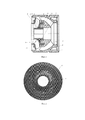
На фиг. 1 изображен разрез ступени погружного многоступенчатого лопастного насоса.In FIG. 1 shows a section through a step of a submersible multi-stage vane pump.
На фиг. 2 изображено рабочее колесо с расположением дренажных отверстий в зоне входной кромки с рабочей стороны лопастей рабочего колеса многоступенчатого лопастного насоса.In FIG. 2 shows the impeller with the location of the drainage holes in the area of the input edge from the working side of the blades of the impeller of a multi-stage vane pump.
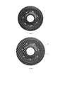
На фиг. 3 изображено рабочее колесо с дренажными отверстиями продолговатой формы, размещенными своей большей стороной вдоль диаметральной линии, проведенной по входным кромкам лопастей рабочего колеса.In FIG. 3 shows the impeller with oblong drainage holes placed with their larger side along the diametric line drawn along the input edges of the impeller blades.
На фиг. 4 изображено рабочее колесо с дренажными отверстиями продолговатой формы, размещенными своей большей стороной параллельно наружной кромки лопастей.In FIG. 4 shows the impeller with oblong shaped drainage holes placed with their larger side parallel to the outer edge of the blades.
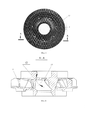
На фиг. 5 изображено рабочее колесо с дренажными отверстиями выполненными наклонными в сторону противоположную направлению вращения рабочего колеса, и на фиг. 6 разрез по линии А-А рабочего колеса, показанного на фиг. 5.In FIG. 5 shows the impeller with drainage holes made oblique in the direction opposite to the direction of rotation of the impeller, and in FIG. 6 is a section along the line AA of the impeller shown in FIG. 5.
Ступень погружного многоступенчатого лопастного насоса состоит из рабочего колеса 1 имеющего ступицу 2, лопасти 3 расположенные между дисками 4 и 5, образующими проточные каналы 6 рабочего колеса и направляющего аппарата 7, включающего верхний диск 8 и нижний диск 9 с размещенными между дисками лопатками 10 и формирующими проточную часть 11 направляющего аппарата 7. Между диском 4 рабочего колеса 1 и направляющим аппаратом 5 размещена разгрузочная камера 12, которая соединяется дренажными отверстиями 13 с проточными каналами 6, образованными дисками 4 и 5 и лопастями 3 рабочего колеса 1,The step of a submersible multi-stage vane pump consists of an
Ступень погружного многоступенчатого лопастного насоса работает следующим образом.The stage of a submersible multi-stage vane pump operates as follows.
При вращении рабочего колеса 1 его лопасти 3 взаимодействуют с перекачиваемой жидкостью, которая поступает по проточной части 11 направляющего аппарата 7 в проточные каналы 6, ограниченные дисками 4, 5 и лопастями 3 рабочего колеса 1. При этом энергия передается потоку жидкости в виде скоростного напора, который в лопастных системах рабочего колеса 1 и направляющего аппарата 7 превращается с статический напор (давление) жидкости. Скоростной и статический напор воздействуют на диски 4 и 5, создавая осевую нагрузку, приживающую рабочее колесо 1 к направляющему аппарату 7. Эта осевая нагрузка уменьшается за счет наличия камеры разгрузки 12, в которой благодаря дренажным отверстиям 13 создается давление, равное давлению в проточных каналах 6 рабочего колеса 1. При размещении дренажных отверстий 13 в зоне входной кромки с рабочей стороны лопасти 3 рабочего колеса 1 это давление будет выше, чем в случае размещения дренажных отверстий ближе к задней кромке лопастей. Таким образом, улучшается разгрузка рабочего колеса и уменьшается износ опорных поверхностей направляющего аппарата и рабочего колеса.When the
Размещение дренажных отверстий 13 в зоне входной кромки с рабочей стороны лопасти 3 рабочего колеса 1 (см. фиг. 2) обеспечивает такой технический результат, как уменьшение циркуляции перекачиваемой жидкости из-за равенства давлений в рабочих каналах и камере разгрузки..The placement of the
Выполнение дренажных отверстий 13 продолговатой формы и их размещение большей стороной вдоль диаметральной линии, проведенной по входным кромкам лопастей 3 рабочего колеса 1 (см. фиг. 3), уменьшает засорение отверстий солями и механическими примесями.The implementation of the
Расположение дренажных отверстий 13 своей большей стороной параллельно наружной кромки лопастей 3 рабочего колеса 1 (см. фиг. 4) обеспечивает подачу жидкости из рабочих каналов в камеру разгрузки 13 с более высоким давлением, что повышает эффективность разгрузки рабочего колеса.The location of the
Выполнение дренажных отверстий 13 наклонными (на фиг. 6 угол наклона обозначен «G») в сторону противоположную направлению вращения рабочего колеса (см. фиг. 5 и фиг. 6) позволяет улучшить вынос механических примесей из камеры разгрузки, так как в данном случае дренажные отверстия работают как наклонные лопасти осевого колеса.The execution of the
Таким образом, дополнительные технические результаты, обусловленные конфигурацией дренажных отверстий и их расположение относительно рабочей стороны лопасти, это - уменьшение засорения отверстий солями и механическими примесями, повышение давления в камере разгрузки и улучшение выноса механических примесей из камеры разгрузки за счет работы каналов в качестве нагнетательных.Thus, additional technical results due to the configuration of the drainage holes and their location relative to the working side of the blade are reduced clogging of the holes with salts and mechanical impurities, increased pressure in the unloading chamber and improved removal of mechanical impurities from the unloading chamber due to the operation of the channels as injection channels.
Следует понимать, что после рассмотрения специалистом приведенного описания с примером осуществления ступени погружного многоступенчатого лопастного насоса, а также сопроводительных чертежей, для него станут очевидными другие изменения, модификации и варианты реализации заявленной полезной модели. Таким образом, все подобные изменения, модификации и варианты реализации, а также другие области применения, не имеющие расхождений с сущностью настоящей полезной модели, следует считать защищенными настоящей полезной моделью в объеме прилагаемой формулы полезной модели.It should be understood that after the specialist has considered the above description with an example of the implementation of a multi-stage submersible vane pump stage, as well as the accompanying drawings, other changes, modifications, and implementation options of the claimed utility model will become apparent to him. Thus, all such changes, modifications and implementation options, as well as other areas of application that do not differ from the essence of the present utility model, should be considered protected by the present utility model in the scope of the attached utility model formula.
Claims (5)
Priority Applications (1)
| Application Number | Priority Date | Filing Date | Title |
|---|---|---|---|
| RU2018121560U RU188224U1 (en) | 2018-08-27 | 2018-08-27 | Submersible multi-stage vane pump stage |
Applications Claiming Priority (1)
| Application Number | Priority Date | Filing Date | Title |
|---|---|---|---|
| RU2018121560U RU188224U1 (en) | 2018-08-27 | 2018-08-27 | Submersible multi-stage vane pump stage |
Publications (1)
| Publication Number | Publication Date |
|---|---|
| RU188224U1 true RU188224U1 (en) | 2019-04-03 |
Family
ID=66087782
Family Applications (1)
| Application Number | Title | Priority Date | Filing Date |
|---|---|---|---|
| RU2018121560U RU188224U1 (en) | 2018-08-27 | 2018-08-27 | Submersible multi-stage vane pump stage |
Country Status (1)
| Country | Link |
|---|---|
| RU (1) | RU188224U1 (en) |
Cited By (3)
| Publication number | Priority date | Publication date | Assignee | Title |
|---|---|---|---|---|
| RU2709404C2 (en) * | 2015-03-20 | 2019-12-17 | Ибара Корпорейшн | Impeller for centrifugal pumps |
| RU2754049C1 (en) * | 2020-12-12 | 2021-08-25 | Игорь Олегович Стасюк | Stage of a multi-stage vane pump |
| RU206628U1 (en) * | 2021-03-06 | 2021-09-17 | Игорь Олегович Стасюк | Stage vane multistage diagonal oval pump |
Citations (7)
| Publication number | Priority date | Publication date | Assignee | Title |
|---|---|---|---|---|
| SU731057A1 (en) * | 1978-11-14 | 1980-04-30 | Институт Горной Механики И Технической Кибернетики Им.М.М.Федорова | Centrifugal pump |
| SU1262127A1 (en) * | 1984-04-11 | 1986-10-07 | Особое Конструкторское Бюро По Конструированию,Исследованию И Внедрению Глубинных Бесштанговых Насосов | Diagonal vane wheel |
| US5224821A (en) * | 1991-02-27 | 1993-07-06 | Aisin Seiki Kabushiki Kaisha | Water pump |
| RU123868U1 (en) * | 2011-12-06 | 2013-01-10 | Научно-производственное общество с ограниченной ответственностью "Фенокс" | CENTRIFUGAL PUMP DRIVING WHEEL |
| RU2550564C2 (en) * | 2013-05-06 | 2015-05-10 | Федеральное государственное унитарное предприятие "Государственный космический научно-производственный центр имени М.В. Хруничева" | Centrifugal pump |
| WO2016160016A1 (en) * | 2015-04-02 | 2016-10-06 | Schlumberger Canada Limited | Balance chambers in electric submersible pumps |
| US20170211582A1 (en) * | 2014-08-26 | 2017-07-27 | Halliburton Energy Services, Inc. | Thrust washer and diffuser for use in a downhole electrical submersible pump |
-
2018
- 2018-08-27 RU RU2018121560U patent/RU188224U1/en active
Patent Citations (7)
| Publication number | Priority date | Publication date | Assignee | Title |
|---|---|---|---|---|
| SU731057A1 (en) * | 1978-11-14 | 1980-04-30 | Институт Горной Механики И Технической Кибернетики Им.М.М.Федорова | Centrifugal pump |
| SU1262127A1 (en) * | 1984-04-11 | 1986-10-07 | Особое Конструкторское Бюро По Конструированию,Исследованию И Внедрению Глубинных Бесштанговых Насосов | Diagonal vane wheel |
| US5224821A (en) * | 1991-02-27 | 1993-07-06 | Aisin Seiki Kabushiki Kaisha | Water pump |
| RU123868U1 (en) * | 2011-12-06 | 2013-01-10 | Научно-производственное общество с ограниченной ответственностью "Фенокс" | CENTRIFUGAL PUMP DRIVING WHEEL |
| RU2550564C2 (en) * | 2013-05-06 | 2015-05-10 | Федеральное государственное унитарное предприятие "Государственный космический научно-производственный центр имени М.В. Хруничева" | Centrifugal pump |
| US20170211582A1 (en) * | 2014-08-26 | 2017-07-27 | Halliburton Energy Services, Inc. | Thrust washer and diffuser for use in a downhole electrical submersible pump |
| WO2016160016A1 (en) * | 2015-04-02 | 2016-10-06 | Schlumberger Canada Limited | Balance chambers in electric submersible pumps |
Cited By (3)
| Publication number | Priority date | Publication date | Assignee | Title |
|---|---|---|---|---|
| RU2709404C2 (en) * | 2015-03-20 | 2019-12-17 | Ибара Корпорейшн | Impeller for centrifugal pumps |
| RU2754049C1 (en) * | 2020-12-12 | 2021-08-25 | Игорь Олегович Стасюк | Stage of a multi-stage vane pump |
| RU206628U1 (en) * | 2021-03-06 | 2021-09-17 | Игорь Олегович Стасюк | Stage vane multistage diagonal oval pump |
Similar Documents
| Publication | Publication Date | Title |
|---|---|---|
| RU188224U1 (en) | Submersible multi-stage vane pump stage | |
| JP5060737B2 (en) | Centrifugal pump and its impeller | |
| US8506236B2 (en) | Counter rotation inducer housing | |
| RU185434U1 (en) | PUMP | |
| CN104314860A (en) | Impeller for low-specific speed centrifugal pump | |
| CN2816434Y (en) | Vortex-adding chamber structure for water pump | |
| US20050226716A1 (en) | Impeller for fuel pumps | |
| US3588280A (en) | Inducers for centrifugal pumps | |
| CN109885886B (en) | Hydraulic design method for reducing hump of multi-stage pump head curve | |
| CN105041719A (en) | Guide vane type opening ring of double-suction centrifugal pump | |
| US1634317A (en) | Impeller balancing and sealing device | |
| RU180414U1 (en) | Submersible multi-stage vane pump stage | |
| RU57395U1 (en) | GUIDING DEVICE FOR STEP OF SUBMERSIBLE CENTRIFUGAL PUMP | |
| RU197931U1 (en) | Free Swirl Submersible Pump | |
| CN205478555U (en) | Centrifugal pump side direction formula spiral delivery chamber | |
| CN207647843U (en) | Energy-efficient high cavitation performance double entry pump | |
| RU2008108327A (en) | SUBMERSIBLE PUMP UNIT FOR PUMPING A GAS-LIQUID MIXTURE | |
| RU205750U1 (en) | Impeller of submersible multistage vane pump | |
| RU2361117C1 (en) | Multistage centrifugal pump | |
| RU194907U1 (en) | PUMP | |
| CN217502089U (en) | Sinking type inlet guide vane for vertical centrifugal pump | |
| CN215980093U (en) | Amphibious water pump impeller | |
| RU2442909C2 (en) | Multi-stage high-speed immersed impeller pump | |
| CN1609458A (en) | Double-priming centrifugal pump | |
| RU204975U1 (en) | Multistage centrifugal pump |