RU180381U1 - DEVICE FOR INDUCTION HEATING - Google Patents
DEVICE FOR INDUCTION HEATING Download PDFInfo
- Publication number
- RU180381U1 RU180381U1 RU2017137985U RU2017137985U RU180381U1 RU 180381 U1 RU180381 U1 RU 180381U1 RU 2017137985 U RU2017137985 U RU 2017137985U RU 2017137985 U RU2017137985 U RU 2017137985U RU 180381 U1 RU180381 U1 RU 180381U1
- Authority
- RU
- Russia
- Prior art keywords
- channels
- heating
- frequency
- heat exchanger
- ferromagnetic plates
- Prior art date
Links
Images

Classifications
-
- H—ELECTRICITY
- H05—ELECTRIC TECHNIQUES NOT OTHERWISE PROVIDED FOR
- H05B—ELECTRIC HEATING; ELECTRIC LIGHT SOURCES NOT OTHERWISE PROVIDED FOR; CIRCUIT ARRANGEMENTS FOR ELECTRIC LIGHT SOURCES, IN GENERAL
- H05B6/00—Heating by electric, magnetic or electromagnetic fields
- H05B6/02—Induction heating
- H05B6/36—Coil arrangements
Abstract
Полезная модель относится к электроэнергетике, а именно к индукционным нагревателям текучих сред, и может быть использована для нагрева воды и других текучих сред в системах с естественной и принудительной циркуляцией нагреваемой среды как в промышленных, так и в бытовых условиях. Целесообразно применение заявляемого устройства для обеспечения автономного отопления и/или горячего водоснабжения при индивидуальном жилищном строительстве. Задача, на решение которой направлена заявляемая полезная модель, - повышение коэффициента мощности и диапазона регулирования температуры нагрева при одновременном упрощении конструкции, повышении надежности и удобства эксплуатации. Поставленная задача решается устройством для индукционного нагрева жидкости, содержащем расположенные в корпусе 1 нагреватель 4, представляющий собой, по меньшей мере, одну плоскую бифилярную катушку Тесла, подключенную к высокочастотному генератору с возможностью изменения частоты в диапазоне от 20 до 120 кГц, с обеих сторон к которой плотно прилегают ферромагнитные пластины 2 и 3, к которым, в свою очередь, примыкает теплообменник в виде каналов 5 и 6 для движения жидкости, форма каналов которого выполнена с возможностью обеспечения максимально возможного пути нагреваемой жидкости вдоль ферромагнитных пластин. 2 ил.The utility model relates to the electric power industry, namely to induction heaters of fluids, and can be used to heat water and other fluids in systems with natural and forced circulation of the heated medium both in industrial and domestic conditions. It is advisable to use the inventive device to provide autonomous heating and / or hot water supply for individual housing construction. The problem to which the claimed utility model is directed is to increase the power factor and the range of regulation of the heating temperature while simplifying the design, increasing the reliability and ease of use. The problem is solved by a device for induction heating of a liquid containing a heater 4 located in the housing 1, which is at least one Tesla flat bifilar coil connected to a high-frequency generator with the possibility of changing the frequency in the range from 20 to 120 kHz, from both sides which are tightly adjacent to the ferromagnetic plates 2 and 3, to which, in turn, is adjacent a heat exchanger in the form of channels 5 and 6 for the movement of liquid, the shape of the channels of which is configured to maximize The possible path of the heated fluid along the ferromagnetic plates. 2 ill.
Description
Полезная модель относится к электроэнергетике, а именно к индукционным нагревателям текучих сред, и может быть использована для нагрева воды и других текучих сред в системах с естественной и принудительной циркуляцией нагреваемой среды, как в промышленных, так и в бытовых условиях. Целесообразно применение заявляемого устройства для обеспечения автономного отопления и/или горячего водоснабжения при индивидуальном жилищном строительствеThe utility model relates to the electric power industry, namely to induction heaters of fluids, and can be used to heat water and other fluids in systems with natural and forced circulation of the heated medium, both in industrial and domestic conditions. It is advisable to use the inventive device to provide autonomous heating and / or hot water supply for individual housing construction
Известен патент на изобретение RU № 2400944 «Вихревой индукционный нагреватель и устройство обогрева для помещений», опубликован 27.09.2010. Используется в системах отопления и водоснабжения. Содержит ферромагнитную емкость цилиндрической формы. К торцевым стенкам цилиндрической емкости с противоположных сторон прикреплены концентрически две металлические трубы с образованием лабиринтного выхода для нагреваемой жидкости. Имеет индукционную обмотку из медного провода, заключенную в герметичный тороидальный цилиндрический корпус из изоляционного немагнитного материала, расположенную в центре и коаксиально с трубами. Подача жидкости в емкость осуществляется по трубе через центр цилиндрического корпуса обмотки.Known patent for the invention RU No. 2400944 "Vortex induction heater and heating device for rooms", published 09/27/2010. It is used in heating and water supply systems. Contains a cylindrical ferromagnetic capacity. Concentrically two metal pipes are attached to the end walls of the cylindrical container from opposite sides with the formation of a labyrinth exit for the heated fluid. It has an induction winding made of copper wire, enclosed in a sealed toroidal cylindrical body of insulating non-magnetic material, located in the center and coaxial with the pipes. The liquid is supplied to the tank through the pipe through the center of the cylindrical body of the winding.
Устройство имеет ряд недостатков, реально снижающих заявленные показатели эффективности: наличие индукционной обмотки в оболочке только из изоляционного материала значительно затрудняет обеспечение электробезопасности и герметичности конструкции; лабиринтная схема движения жидкости удлиняет путь, но по приведенной схеме электрическое сопротивление индуктируемому току возрастает и, следовательно, снижается величина тока, что уменьшает количество генерируемого тепла; все элементы устройства имеют одинаковую толщину и сложную конфигурацию, что усложняет систему формирования структуры электромагнитного поля, а следовательно и выбор оптимальных параметров по заявленным показателям эффективности.The device has a number of disadvantages that actually reduce the declared performance indicators: the presence of an induction winding in the shell of only insulating material greatly complicates the provision of electrical safety and tightness of the structure; the labyrinth scheme of fluid movement extends the path, but according to the above diagram, the electrical resistance of the inducted current increases and, consequently, the current decreases, which reduces the amount of heat generated; all elements of the device have the same thickness and complex configuration, which complicates the system of formation of the structure of the electromagnetic field, and therefore the choice of optimal parameters according to the declared performance indicators.
Наиболее близким к заявляемому объекту является патент США № US 2010/0213190 от 26.08.2010 «Проточный индукционный нагреватель» для нагрева жидкостей, включающий индукционную катушку, размещенную в камере с ферромагнитными стенками, вдоль которых проходят каналы для движения жидкости. Нагрев жидкости происходит от ферромагнитных стенок камеры индуктора. Устройство не требует дополнительного электромагнитного экранирования.Closest to the claimed object is US patent No. US 2010/0213190 dated 08/26/2010 "Flowing induction heater" for heating liquids, including an induction coil placed in a chamber with ferromagnetic walls along which pass channels for the movement of liquid. Liquid heating occurs from the ferromagnetic walls of the inductor chamber. The device does not require additional electromagnetic shielding.
Конструкция камеры индуктора и каналов для движения жидкости выполнена из тонкостенных ферромагнитных труб, собранных коаксиально на общей крышке, равной толщины с трубами. Для подачи и отвода воды имеются входные боковые и центральный выходной патрубки. Устройство допускает возможность работы в широком диапазоне частот от 50-400 кГц. Для повышения эффективности нагрева предлагается в каналах для движения жидкости устроить плоские ребра в форме спирали, которые увеличивают время и путь движения жидкости вдоль внешней нагревающей ферромагнитной стенки камеры индуктора.The design of the inductor chamber and channels for the movement of liquid is made of thin-walled ferromagnetic pipes assembled coaxially on a common lid of equal thickness with the pipes. For supply and drainage of water, there are inlet side and central outlet pipes. The device allows the ability to work in a wide frequency range from 50-400 kHz. To increase the heating efficiency, it is proposed to arrange flat ribs in the form of a spiral in the channels for the movement of the liquid, which increase the time and path of the liquid along the external heating ferromagnetic wall of the inductor chamber.
Недостатком устройства является малая толщина стенок камеры и крышки индуктора, что приводит к искажению формы электромагнитного поля и, как следствие, снижению коэффициента мощности (cos ϕ), а применение однотипной конструкции по диапазону частот с 8-кратным перекрытием диапазона увеличит потери и в целом приведет к низкому коэффициенту полезного действия.The disadvantage of this device is the small thickness of the walls of the chamber and the cover of the inductor, which leads to a distortion of the shape of the electromagnetic field and, as a consequence, a decrease in the power factor (cos ϕ), and the use of the same type design in the frequency range with 8-fold overlap of the range will increase losses and generally lead to to low efficiency.
Задача, на решение которой направлена заявляемая полезная модель, - устранение указанных недостатков, а именно - повышение коэффициента мощности и диапазона регулирования температуры нагрева при одновременном упрощении конструкции, повышении надежности и удобства эксплуатации.The task to which the claimed utility model is directed is to eliminate these drawbacks, namely, to increase the power factor and the range of regulation of the heating temperature while simplifying the design, increasing the reliability and ease of use.
Поставленная задача решается тем, в устройство для индукционного нагрева жидкости, содержащем расположенные в корпусе нагреватель, вдоль которого расположен теплообменник в виде каналов для движения жидкости, нагреватель представляет собой по меньшей мере одну плоскую бифилярную катушку Тесла, подключенную к высокочастотному генератору с возможностью изменения частоты в диапазоне от 20 до 120 кГц, с обеих сторон к которой плотно прилегают ферромагнитные пластины, к которым, в свою очередь, примыкает теплообменник, форма каналов которого выполнена с возможностью обеспечения максимально возможного пути нагреваемой жидкости вдоль ферромагнитных пластин.The problem is solved in that in a device for induction heating of a liquid containing a heater located in the housing, along which a heat exchanger is arranged in the form of channels for the movement of liquid, the heater is at least one Tesla flat bifilar coil connected to a high-frequency generator with the possibility of changing the frequency range from 20 to 120 kHz, on both sides of which are tightly adjacent ferromagnetic plates, to which, in turn, is adjacent a heat exchanger, the shape of the channels of which configured to provide the maximum possible path of the heated fluid along the ferromagnetic plates.
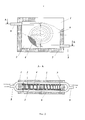
На фиг. 1 приведена схема индукционного нагревателя жидкостей с теплообменником, каналы которого расположены в форме змеевика, На фиг. 2 приведена схема индукционного нагревателя жидкостей, каналы теплообменника которого расположены в форме плоской спирали (улитки).In FIG. 1 shows a diagram of an induction fluid heater with a heat exchanger, the channels of which are arranged in the form of a coil, FIG. 2 shows a diagram of an induction fluid heater, the heat exchanger channels of which are arranged in the form of a flat spiral (cochlea).
В герметичном корпусе 1 размещены ферромагнитные пластины 2 и 3, между которыми расположена плотно прилегающая к ним плоская бифилярная катушка Тесла 4 (см. патент США №512340). К ферромагнитным пластинам 2 и 3 приварены пластины 5 и 6 теплообменника, на которых выполнены каналы для движения жидкости. Конфигурация каналов должна обеспечить максимально возможный путь нагреваемой жидкости вдоль ферромагнитных пластин 2 и 3. В варианте 1 она имеет форму змеевика. В варианте 2 конфигурация каналов для движения жидкости, выполненных в пластинах 2 и 3 имеет форму спирали (фиг. 2). Свободный объем корпуса 1 заполнен термоизоляционным материалом 7, например, базальтом. Каналы в пластинах 5 и 6 объединены в единую проточную систему входным патрубком 8 и выходным патрубком 9. Плоская бифилярная катушка 4 соединяется с источником высокочастотного электропитания (на чертеже не показан) с возможностью регулирования частоты в диапазоне от 20 до 120 кГц. В случае, когда одной катушки не достаточно для нагрева нужного количества воды (например, при большом расходе в проточной системе, низкой начальной температуре воды в зимнее время или при подъеме ее с глубокой артезианской скважины), можно последовательно расположить несколько катушек, увеличив при этом длину пластин 5 и 6 теплообменника, для обеспечения нужной температуры на выходе.In the sealed
Нагреватель работает следующим образом. Холодная вода подается в систему нагрева через патрубок 8. При включении плоской бифилярной катушки Тесла 4 в систему высокочастотного электропитания возникает пульсирующее магнитное поле, которое вызывает в ферромагнитных пластинах 2 и 3 возникновение вихревых токов, которые нагревают эти пластины, а они передают тепло в каналы с водой, выполненные в пластинах 5 и 6. Особенностью работы плоской бифилярной катушки Тесла 4 является то, что величина магнитного поля зависит от частоты питающего напряжения, максимума она достигает при частоте 120 кГц, которая близка к резонансной частоте катушки 4. От величины магнитного поля зависит температура нагрева воды, циркулирующей в каналах пластин 5 и 6.The heater operates as follows. Cold water is supplied to the heating system through
Плоская бифилярная катушка Тесла 4 выполнена из медного провода сечением от 0,1 до 0,8 мм. Намотка катушки выполняется бифилярным способом и подключается к двухфазной электрической сети переменного тока через частотный модулятор (не показан). На выходном патрубке устанавливается термометр и клапан сброса избыточного давления (на чертеже не показаны). На входном патрубке устанавливается циркуляционный насос, позволяющий увеличить количество прохождения теплоносителя через теплообменник (не показан). При изменении частоты частотного модулятора увеличивается или уменьшается выделение тепловой энергии. В разрыв между блоком питания и частотным модулятором устанавливается датчик температуры с блоком управления. Блок управления позволяет выставлять температурный режим, требуемый для теплоносителя. При достижении требуемой температуры датчик дает сигнал на отключение и электрическая цепь разрывается. При понижении температуры датчик замыкает цепь, включая катушку на период достижения требуемой температуры. При потреблении электрической энергии из сети в 1 кВт нагрев теплообменника объемом 1 литр до температуры 90°С достигается за короткий промежуток времени 180 секунд, что свидетельствует о повышении энергоэффективности заявляемого нагревателя.Tesla 4 flat bifilar coil is made of copper wire with a cross section of 0.1 to 0.8 mm. Coil winding is carried out in a bifilar manner and is connected to a two-phase AC electric network through a frequency modulator (not shown). A thermometer and an overpressure relief valve are installed on the outlet pipe (not shown in the drawing). A circulation pump is installed at the inlet pipe, which allows increasing the amount of coolant passing through the heat exchanger (not shown). When the frequency of the frequency modulator changes, the release of thermal energy increases or decreases. A temperature sensor with a control unit is installed in the gap between the power supply and the frequency modulator. The control unit allows you to set the temperature regime required for the coolant. When the required temperature is reached, the sensor gives a trip signal and the electric circuit is broken. When the temperature drops, the sensor closes the circuit, including the coil for the period when the desired temperature is reached. With the consumption of electric energy from the network of 1 kW, heating a heat exchanger with a volume of 1 liter to a temperature of 90 ° C is achieved in a short period of 180 seconds, which indicates an increase in the energy efficiency of the inventive heater.
Преимущества:Benefits:
- Не требуется времени на разогрев (в отличие от котлов с ТЭНами) - энергия выделяется прямо в толще теплообменника, сразу с заданной мощностью. Это вплотную приближает индукционный нагреватель по удобству к газовым.- No heating time is required (unlike boilers with heating elements) - energy is released directly in the thickness of the heat exchanger, immediately with a given power. This closely brings the induction heater in convenience to the gas.
- КПД около 90% (в отличие от 60-70% у электрических тэновых котлов) благодаря отсутствию утечки потоков тепла от раскаленных резистивных нагревательных элементов.- Efficiency is about 90% (in contrast to 60-70% for electric heating boilers) due to the absence of leakage of heat fluxes from incandescent resistive heating elements.
- Точно поддерживает заданную температуру теплоносителя благодаря датчику температуры, призванному улавливать температуру теплообменника.- Accurately maintains the set temperature of the heat carrier thanks to the temperature sensor urged to pick up temperature of the heat exchanger.
- Зависимость мощности от напряжения сети практически отсутствует. Подключение к обычной сети 220 В через обычную бытовую розетку.- The dependence of power on the mains voltage is practically absent. Connection to a regular 220 V network through a regular household outlet.
- Большой диапазон режимов температуры от 20 до 90°С.- A wide range of temperature modes from 20 to 90 ° C.
- При использовании обычной воды в качестве теплоносителя не образуется накипь на стенках теплообменника.- When using ordinary water as a heat transfer medium, scale does not form on the walls of the heat exchanger.
- Отличается простотой конструкции и, следовательно, надежностью, долговечностью, простотой эксплуатации и пожаробезопасностью.- It is distinguished by its simplicity of design and, therefore, reliability, durability, ease of operation and fire safety.
- Благодаря использованию нескольких катушек, варьированию их размеров появляется возможность на базе одного конструктивного решения создать унифицированную линейку нагревателей, рассчитанных на разные жидкости и разный расход, что расширяет область применения.- Thanks to the use of several coils, the variation of their sizes, it becomes possible on the basis of one design solution to create a unified line of heaters designed for different liquids and different flow rates, which expands the scope.
Claims (1)
Priority Applications (1)
| Application Number | Priority Date | Filing Date | Title |
|---|---|---|---|
| RU2017137985U RU180381U1 (en) | 2017-10-31 | 2017-10-31 | DEVICE FOR INDUCTION HEATING |
Applications Claiming Priority (1)
| Application Number | Priority Date | Filing Date | Title |
|---|---|---|---|
| RU2017137985U RU180381U1 (en) | 2017-10-31 | 2017-10-31 | DEVICE FOR INDUCTION HEATING |
Publications (1)
| Publication Number | Publication Date |
|---|---|
| RU180381U1 true RU180381U1 (en) | 2018-06-09 |
Family
ID=62560897
Family Applications (1)
| Application Number | Title | Priority Date | Filing Date |
|---|---|---|---|
| RU2017137985U RU180381U1 (en) | 2017-10-31 | 2017-10-31 | DEVICE FOR INDUCTION HEATING |
Country Status (1)
| Country | Link |
|---|---|
| RU (1) | RU180381U1 (en) |
Cited By (1)
| Publication number | Priority date | Publication date | Assignee | Title |
|---|---|---|---|---|
| RU202044U1 (en) * | 2019-11-29 | 2021-01-28 | Дмитрий Александрович Дурбале | Device for heating a flowing heat carrier (water) using controlled energy resonance |
Citations (4)
| Publication number | Priority date | Publication date | Assignee | Title |
|---|---|---|---|---|
| SU378427A1 (en) * | 1971-02-22 | 1973-04-18 | INDUCTION HEATER | |
| US3808115A (en) * | 1969-07-23 | 1974-04-30 | Allis Chalmers Mfg Co | Surface fluorinated hydrogen containing material and process for making |
| SU1494252A1 (en) * | 1987-03-04 | 1989-07-15 | Уфимский авиационный институт им.Серго Орджоникидзе | Device for even induction heating of flat ingots |
| RU2393649C1 (en) * | 2009-03-02 | 2010-06-27 | Владимир Константинович Гаврилов | Induction heater of bushing surface |
-
2017
- 2017-10-31 RU RU2017137985U patent/RU180381U1/en not_active IP Right Cessation
Patent Citations (4)
| Publication number | Priority date | Publication date | Assignee | Title |
|---|---|---|---|---|
| US3808115A (en) * | 1969-07-23 | 1974-04-30 | Allis Chalmers Mfg Co | Surface fluorinated hydrogen containing material and process for making |
| SU378427A1 (en) * | 1971-02-22 | 1973-04-18 | INDUCTION HEATER | |
| SU1494252A1 (en) * | 1987-03-04 | 1989-07-15 | Уфимский авиационный институт им.Серго Орджоникидзе | Device for even induction heating of flat ingots |
| RU2393649C1 (en) * | 2009-03-02 | 2010-06-27 | Владимир Константинович Гаврилов | Induction heater of bushing surface |
Cited By (1)
| Publication number | Priority date | Publication date | Assignee | Title |
|---|---|---|---|---|
| RU202044U1 (en) * | 2019-11-29 | 2021-01-28 | Дмитрий Александрович Дурбале | Device for heating a flowing heat carrier (water) using controlled energy resonance |
Similar Documents
| Publication | Publication Date | Title |
|---|---|---|
| US5216215A (en) | Electrically powered fluid heater including a coreless transformer and an electrically conductive jacket | |
| EP2213140B1 (en) | Flow-through induction heater | |
| RU87856U1 (en) | LIQUID INDUCTION HEATING DEVICE | |
| RU180381U1 (en) | DEVICE FOR INDUCTION HEATING | |
| RU2400944C1 (en) | Vortex induction heater and heating device for premises | |
| JP2008281287A (en) | Electric continuous water heater | |
| ES2912501T3 (en) | Point of Use Induction Water Heater | |
| CN203249380U (en) | Electromagnetic water boiler with ultrasonic frequency | |
| CN207661962U (en) | Electromagnet water heater | |
| RU93507U1 (en) | INDUCTION LIQUID HEATER | |
| WO2018147758A1 (en) | Induction fluid heater | |
| RU86832U1 (en) | FLUID INDUCTION HEATER | |
| CN214223421U (en) | High-frequency electromagnetic water heater | |
| CN2656876Y (en) | Electromagnetic water heater | |
| RU2797032C1 (en) | Fluid induction heater | |
| UA148606U (en) | DEVICE FOR INDUCTION HEATING | |
| KR101809169B1 (en) | Apparatus for Heating Fluid | |
| KR101664001B1 (en) | Low-frequency induction heating device for boiler | |
| RU174499U1 (en) | INDUCTION HEATER | |
| RU2625719C2 (en) | Induction liquid heater | |
| CN210463555U (en) | Water heater with electromagnetic heating function | |
| CN210014549U (en) | Novel electromagnetic heating device for rapidly heating flowing liquid | |
| RU2094959C1 (en) | Fluid medium electric heater | |
| CN207202722U (en) | A kind of electromagnetic induction heating water dispenser | |
| RU2267869C1 (en) | Flow inducing liquid heater |
Legal Events
| Date | Code | Title | Description |
|---|---|---|---|
| MM9K | Utility model has become invalid (non-payment of fees) |
Effective date: 20181101 |